
Hello everyone, I'm new to the forum - thought I might find the help I need here.

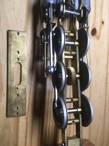
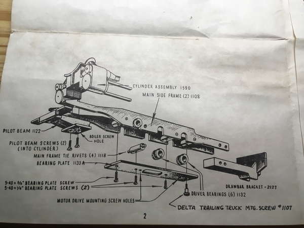
I've recently started assembling a vintage General Models Corporation Pacific, which uses the same mechanism as the All-Nation locomotives. So, here's my problem... When I try to install the "bearing plate" (the plate that mounts underneath the frame and retains the drivers), the second and third drivers begin to bind up. This is just with the screws finger tight. Is there a known solution to this?

Last edited by Johnbeere
Original Post

Replies sorted oldest to newest

Is in possible the bearings have a flat side, that should be down against the plate, while the rest is in the slot.   I built an AN 4-4-0 years ago and did not have any issues like this.  

Another solution if there is not enough height for the axles is to file the top of the slot in the frame to gain a few thousandths.    And I would suggest bolting the two frame halves together and filing both sides at the same time to keep them as much the same as possible.

Yeah, it's definitely hitting the bearings on mine. Maybe someone could look at their All-Nation locomotive for me and see if it does clamp on the frame? The slots for the bearings may not be milled deep enough on my locomotive. It would be really appreciated if someone could measure how deep those slots go for them so I know for sure that's my issue.

It's hard to take pictures of this - there's not really any good angles. The last photo I posted shows the locomotive upside down, looking between the frame and plate to show how much the bearings protrude.

I think you may be missing some sort of spacer piece that goes between the plate and the frame. There are four holes in the mounting plate that go into the cross-members. The plate has three additional holes. For what are they used? Do the holes in the plate align with the holes in the cross-members? If the motor is mounted to the top of the plate, the plate height may be critical for proper engagement of the motor worm gear to the spur gear. It may be possible to put three washers between the plate and the cross-members. The front cross-member is at a different height and looks like it needs a longer screw. Are there drawings in the instructions?

MELGAR

Last edited by MELGAR

Something is not right. Is the frame assembled perfectly square? Do the bearings fit snugly or tightly into the frame slots? They should not be free to rotate within the frame. Your original complaint was that installing the plate caused the drivers to bind, even without fully tightening the screws. It's hard to believe that slight tightening of the four mounting screws squeezed the bearings enough to cause binding. Are there spacers in the kit?

MELGAR

Last edited by MELGAR

Yes, the frame is as perfectly square as I could get it - in my troubleshooting I held a straight edge to both sides and got it as close to square as possible. The bearings are a loose fit in the frame, until the plate is lightly tightened on. All the axles spin freely in their bearings - with the plate removed, and rotating the wheels by hand, the bearings aren't turning. The kit did come with two sets of two different kinds of spacers - I'm not sure what they're for, but since they're not shown or specified to be used for this purpose, I don't think they're to be used here.

My thought of what is actually happening is that the bearings might be twisting a little in the frame when the plate is tightened on them.

Add Reply

Post

OGR Publishing, Inc., 1310 Eastside Centre Ct, Suite 6, Mountain Home, AR 72653
800-980-OGRR (6477)
www.ogaugerr.com

×
×
×
×
Link copied to your clipboard.
×
×