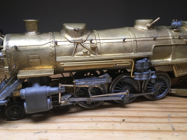
So today I tackled a couple of the soldering jobs I had to do. Soldering definitely isn't my strong suit, but it went okay.

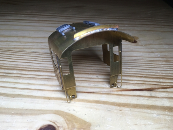
First, I soldered together the cab - I needed to solder on the handrails, solder the back of the cab on, and solder the smoke deflector on. It turned out pretty well, here's what it looks like:
I also needed to dismantle the trailing truck and resolder it, as it was assembled very crooked when I got it. My soldering iron couldn't melt all the solder at once, so I took it outside and got it apart with a torch. I took this as an opportunity to clean the trailing truck wheels, as they were a little rusty - most of the rust came off after soaking the wheels in some Simple Green. (I'm not sure why the Simple Green worked that well to get the rust off, but most of it came off after a short soaking. It was just surface rust, though.) I then soldered the trailing truck back together, my first attempt didn't go well - the solder joint broke after cleaning up the solder with a file, I don't think it was deep enough into the joint. Anyway, I soldered it back a second time, this time taking more care to get solder into the joint, and it's holding well now.

Attachments

Images (1)
  • mceclip0

You have the skills.  Just consider this a learning experience, and soon you will be building your own.

Plug and redrill.  Don't try to drill on assembly; just measure and get the hole dead center on the bottom.

extend the backhead further aft with a brass spacer.  Many steam locomotives had the backhead almost even with the rear cab bulkhead.  You won't have to go that far - an eighth of an inch of brass, and some putty . . .

I don't really have the stock or tools to make the spacer, so it seems much easier to me to just create a groove in the backhead. The backhead is about 1/8 thick, I need to make the groove about 1/16 deep, which isn't too bad.

The instructions say that I should screw the backhead on, but there aren't any good positions for screws - I'm thinking that I'll ultimately try to solder it on.

Well, what you don't see is before I smoothed it out with a lot of filing... The solder was cooling down very quickly so it globbed up, even with my soldering iron as hot as it could go. I definitely have a lot left to learn when it comes to soldering. What I am pretty good with, though, is filing it down so you can't see the mess.

Another update, I've been busy lately, but finally got around to do some more soldering jobs I wanted to do. First off, I got the screw hole in the smokebox filled, in preparations for re-drilling it. I'm very new to soldering with a torch rather than an iron, but it went well and the solder seemed to flow into the joint nicely.

I also decided that I needed to resolder the backhead properly, with a torch this time. I wasn't happy with the big blobs that the solder had formed on the first attempt, rather than properly flowing into the joint. Unfortunately, this means that the backhead ultimately ended up moving a little, so I have more filing work to smooth it out again, but it won't take as long as last time. It turned out much nicer this go around, since I had enough heat to create a much better joint.

I'll continue to give updates as I get work done on it - I've been busy lately so I'm not sure how often that will be.

So, I haven't done much to the locomotive recently. While trying to tap a hole for one of the boiler front screws, the tiny 0-80 tap broke off into the hole, and I left it like that. Well, today I finally got the tap out and the hole filled to do it again... And I broke another tap. I probably twisted it too hard, but I was struggling to figure out why it was binding up. While tapping it, I periodically cleared the chips and even passed my drill bit through the hole each time I cleared the chips, as I thought that may help. I also lubricated the tap... Yet it still broke. Before I break a third tap (after buying replacements for my broken two), any ideas why I might be struggling on this? It entered the hole without issue, but it started to get harder once it was about 2/3 through.

What kind of tap?  Greenfield, or a four dollar hobby tap?

Drill the hole all the way through, and you stand a chance of driving the broken part out the bottom.

Also, a #55 drill will give you plenty of threads, yet allow easier tapping.

Ten years ago, a good tap was eight bucks.  Mine break after several hundred holes, and I buy them three at a time.  Have no idea what a good tap costs now.

I got the taps from McMaster - I think they were about ten bucks each. I don't have a #55 drill, so I used the closest I had, which was a #57. However, I don't think that's my issue, since the tap happily threaded the first half of the hole. This hole goes all the way through, and exits sort of halfway into the wall of the casting - so maybe when I drilled it the bit deflected? But I'm not sure that's my issue, since the tap wasn't yet exiting the hole. Admittedly, I'm fairly new to tapping holes, this kit is the first time I've actually had to buy taps, so I may be doing something wrong without realizing it.

What taps do you recommend, and where do you buy them?

Yes - I use a Dremel cutoff disc and a magnifying lamp.  I then test on a scrap to see two spirals before using it on anything valuable.

Yes - a #57 drill simply causes tap breakage.  Never use a drill smaller than recommended, no matter the size.  Henry Pearce told me he always used one size larger, and his kits are still bulletproof.

Some cutting fluids are better than others - the little yellow can from Ace is ok.  Never tap dry, and never use just plain oil.

It's been quite some time since I did any work on the locomotive, but I've finally done some more.

I really didn't like the floor that was cast as part of the backhead, so I decided to make my own floor out of a sheet of brass, and solder it into place. I then removed the old floor by cutting it off with a Dremel tool and then finally filing it into shape to keep the piping detail intact.

This locomotive has a habit of fighting me every step of the way - I realized one of the holes for the pins that mount the cab was drilled in the wrong place, so I had to fill and re-drill it. That's at least the third or fourth hole I've had to do that for.

mceclip0

I also decided to add a handrail on either side of the cab and on the sand dome, based on details found on ACL 1504.

mceclip1mceclip2mceclip3

Attachments

Images (4)
  • mceclip0
  • mceclip1
  • mceclip2
  • mceclip3

Great job underway!   With the hand rails added above the cab windows, be sure to also add  toe boards  along the bottom edge of the cab sides. Check your reference photo carefully in that area to see them.  The hand rails and toe boards were  for a crew member to either climb out of the cab window or get around the cab from the firing deck, to go forward on the side running boards.  Done at terminals when servicing the locomotive.

S. Islander

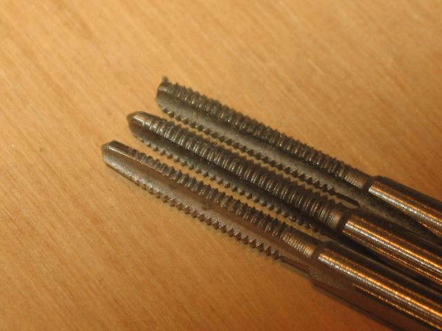
A tap set, has three pieces. The taper tap is a starter.  There is a middle tap to increase the thread length.  Finish, (or bottom-ing) tap completes the project. Taper tap, bottom of this picture, finish tap top.  Acquired patience  an important part of a tap set.  A broken tap is almost impossible to remove, IMO.   Surprisingly there are oil products designed for thread cutting.


Last edited by Mike CT
@S. Islander posted:

Great job underway!   With the hand rails added above the cab windows, be sure to also add  toe boards  along the bottom edge of the cab sides. Check your reference photo carefully in that area to see them.  The hand rails and toe boards were  for a crew member to either climb out of the cab window or get around the cab from the firing deck, to go forward on the side running boards.  Done at terminals when servicing the locomotive.

S. Islander

Thanks! Is the part I highlighted in this photo a toe board? I'll need to figure out how to model it - and probably buy brass strips, since I don't have any yet.

(Added a photo without the highlight so that it's clearer.)

Attachments

Images (2)
  • mceclip0
  • mceclip1
Last edited by Johnbeere

Unrelated, sort of, is the AN Mountain.  This one, I am assured, is on the tracks:

All Nation Doorstops 003

Got it at Chicagoland - they said $35, and I accepted.  You can maybe see why I have spare All Nation drivers to share.  Came without a tender, which was fine with me - I like Lobaugh tenders, or scratchbuilt.  None of the AN tenders thrill me, least of all the Mountain tender.

Attachments

Images (1)
  • All Nation Doorstops 003

Both those locomotives look great. I think I've seen a picture of the Pacific before, but you've done some work to it since.

@bob2 posted:

Possible.  Difficult to tell with the highlight.  The white outlined part is the original toe board.

I added a second photo without the highlight - maybe it's easier to see.

By the way, I've been looking for an O scale Cole trailing truck for my Pacific with no luck, though I've found Hodges trailing trucks. Any ideas where I might find one?

Last night I worked on mounting the tanks and piping... I had to use a Dremel to grind away the boiler band behind both tanks to allow them to sit flat against the boiler to avoid them sticking out from under the running boards.

But I've ran into an issue - the piping, even when sitting closely next to the tank, sticks out far too much. So much that I can't even mount the piping brackets.

I'm considering extending the running boards from the boiler further, I think they are too thin - shouldn't they be the full width of the locomotive?

If I do that, how would I go about it? I think I could either solder or JB Weld brass strips onto the edges, and then file them to match the original profile, but I'm not sure if that's the best way to do it.

Attachments

Images (2)
  • mceclip0
  • mceclip1

I agree - widen them.  Clean the brass, then pin it in place.  Flux, put tiny flattened chips of 60/40 solder along the seam, and carefully heat from the bottom with a propane or mapp torch.

Pins can still be had from a basket supplier in New England - Nantucket, or somebody like that.  Really nice folks.

I used to get them from Coles Power Models.  When Betty retired they went up to 5 cents each.  A little expensive for me.

I've started assembling the tender. There's still a lot of details to add, but it's taking shape. The tender is supposed to be assembled with small brass screws holding each piece to the next, but someone in the past drilled all the holes to assemble it... In the wrong places. Even if they were correctly located, it seems like it would be a huge pain to assemble, so I decided to try using JB Weld to hold the entire thing together. I'm happy with the result - I was able to get each casting exactly where I wanted it by carefully clamping everything in place, and it seems sturdy.

mceclip0

I plan on forming a coal bunker out of a sheet of brass, and adding a coal pusher to it. I may also change out the trucks - either with an old set of Auel Super-Detailed trucks or a set of Walthers trucks to match the real tender trucks on ACL 1504.

Attachments

Images (1)
  • mceclip0

It was quite a lot of work, but I've finished widening the running boards. After looking closer at them, it turns out that they were different widths on either side (the fireman's side running boards were shorter), and the edges weren't straight on either side. I first added material where they curved in to straighten them, then added a single layer of brass strips on one side, and two layers on the other. I'm happy with the result - they're much better than they started out.

Here's hoping that I don't run into any more big issues - this kit has fought me every step of the way, but I'm learning.

Attachments

Images (1)
  • mceclip1

As good a place as any to add some mechanism comments.  Lee just sent me an Atlantic with some sort of problem in the mechanism.  The All Nation mechanisms are as dirt-simple as they come, but as with all 2-rail, they usually have some problems right out of the box.

Caveat: even brain surgery is easy if you know how to do it.  It took me years to really understand the following:

First, almost all steam drivers are "off" a teeny bit.  All Nation are closer than most, but even they can be off a few thousandths one way or another.

Check the quarter!  Do that by installing one set of side rods, placing them at top or bottom dead center, and checking the other side to make sure the crankpins are exactly on a straight line parallel to the axle centerlines.  It is not necessary that they be 90 degrees, just all the same.

Check the crankpin throw and/or the siderod fit - rotate each side through front or back dead center with that side's rods installed.  Note any binding, and fix it.

Once in a while a mechanism will pass all those tests, and still bind up at the 45 degree point.  Place the mechanism in the binding position, and remove a crankpin (or for Lobaugh, a crankpin cap).  Look in there and see which way the rod has moved with respect to the crankpin center.  In Lee's case, this was the problem, and with three strokes of a small rat tail file the mechanism was free and glass-smooth.

You really have to have the mechanism rolling free with all side rods on before you add the main rods, and indeed you want to do those one at a time. 

Even a bullet-proof All Nation mechanism will not "fix itself."  You need to do all these steps on a kit-built O Scale model.

You will not believe the headaches I have suffered discovering these simple things.  I have models with same driver diameters, yet crankpin throws off by a 1/32"!  The only real cure for that is plugging and re-drilling the driver.

This may be the wrong spot for this - hiding the ball, so to speak.  But I bet most All Nation fans will spot it.  I will do it again on a Lobaugh thread if anybody cares, and add my "quarter-check" mechanism.  Yes, those keys are no guarantee - you need a jig and Loctite.

Add Reply

Post

OGR Publishing, Inc., 1310 Eastside Centre Ct, Suite 6, Mountain Home, AR 72653
800-980-OGRR (6477)
www.ogaugerr.com

×
×
×
×
Link copied to your clipboard.
×
×