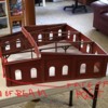
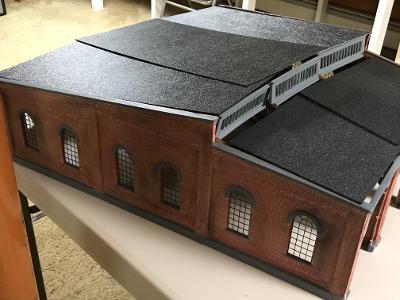
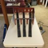
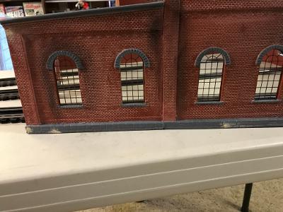
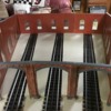
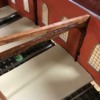
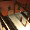
In the process of building the #320  3-stall RH from Korber and, after searching some of the threads on this subject, I have a few questions:

1. Is there a preferred sequence for gluing up the panels ? The directions seem to suggest that a front and rear panel be first glued to each side wall, but it almost seems like all the front and rear panels should be glued together first and then the side walls.

2. Are the vertical uprights at each end of the wooden beams supposed to butt right up against the front and real panels or are the ends of the top beams supposed to butt up against the panels ?

3. Is there a preferred material to use for flooring and would it make sense to install the floor as one large panel and then trace and cut out from the bottom where each individual track is going to go (rather than cutting a section at a time on each side of the tracks) ?

4. It looks like some people are using Plastruct lamps with LED's. Is there a newer/better method of lighting the RH, possibly using LED strips with built-in resistors ?

Thanks


Last edited by Richie C.
Original Post

Replies sorted oldest to newest

Richie:
See below -

1. Is there a preferred sequence for gluing up the panels ? The directions seem to suggest that a front and rear panel be first glued to each side wall, but it almost seems like all the front and rear panels should be glued together first and then the side walls.
I have built long structures both ways. It ends up what you feel most comfortable with. With a side wall glued to a front or rear panel you end up gluing the remainder with the walls standing up. If you glue the sections (front, back, sides etc) as a unit then you are gluing them flat on your work service. I prefer this method since among other things it allows me to glue supports and spacers to the inside of the walls and use weights to hold until the glue sets. Just make sure the instructions are not saying what order for a specific reason (maybe fit).

2. Are the vertical uprights at each end of the wooden beams supposed to butt right up against the front and real panels or are the ends of the top beams supposed to butt up against the panels ?
I have never built this kit so don't know. My assumption is that if you are building the internal wood frame as a standalone unit you want some space between the uprights and the walls. if your intent is to make the walls and wood frame one unit then glue them to the walls. If this is your intent just make sure what ever supports you glued onto the walls in the first place don't interfere with placement of the wood superstructure.

3. Is there a preferred material to use for flooring and would it make sense to install the floor as one large panel and then trace and cut out from the bottom where each individual track is going to go (rather than cutting a section at a time on each side of the tracks) ?
Flooring is basically your choice from a whole bunch of different methods from plain hardboard to scribed wood sheets. With hardboard yea you could use one panel, trace out the track and cut it into pieces. For scribed wood the best I have seen is 8 inches wide so you would be working with several pieces.

4. It looks like some people are using Plastruct lamps with LED's. Is there a newer/better method of lighting the RH, possibly using LED strips with built-in resistors ?
There are Woodland Scenic lamps though I think you are talking about interior hanging industrial style lamps. For this I use Plastruct. See attached file. However be aware of the LED lights you buy. Those that come with  built in resistors will not fit through the tubing. If you use LED you will have to purchase those without resistors and attach your own after the lamp is in the tubing.


Attachments

Thanks, Joe - very informative. AFAIK, this kit is exactly the same as the #304 kit, just slightly smaller and uses the same wood posts and beams (what you may be calling the wooden superstructure) - see the four glued up wood post and beam structures in the attached mock up pics. It looks like two of them glue to the inside of each side wall and two sit in the middle of the RH.

You can see where the top beams of mine extend well past the front and rear panels and I am just trying to figure out if the ends of those beams should be cut back to fit inside the panels and glue them to the front and rear panels or if they should be cut back even more to where the vertical posts meet those beams and then the face of the vertical posts gets glued to the front and rear panels. 

My intent is to have them be part of the structure and not standalone units.  Hope I'm making sense.


RPUNDHOUSE 1InkedROUNDHOUSE 2_LI

Attachments

Images (2)
  • RPUNDHOUSE 1
  • InkedROUNDHOUSE 2_LI
Last edited by Richie C.

Richie:

From the photos it looks like the vertical posts line up with the seams between individual walls. If so perhaps the instructions mention using them as supports to glue individual wall units together? If you glue the verticals to the walls then cut the beams to fit inside and butt against the walls . If nothing else these beams will help straighten the bow in the walls. You may have to purchase separate strips of basswood and glue onto the walls to help straighten out the warp. I do this all the time with Korber walls. Just add them after you have glued in the normal posts and beams. Purchase the basswood the same size as the posts if possible.

Looking at the photos I would say the best plan is to glue the beams and posts to the walls.
Joe

Started with a base material, and built a two layer floor, 1st layer to tie height, 2nd layer close to top of rail/slightly below.  Finish floor, luan board, spackled, sanded and primed before color finish paint.   Wall panels were glued to the edge, shown in the picture.  I built (2) 304 houses.   Fort Pitt High Railer Modular house   My layout house


Floor layers. 

Additional wood framing. 

Last edited by Mike CT

The sides should cover the back and front ends, meaning they are sandwiched between the sides.  

From the looks of it the wood pieces are a bit too long front to back, the should be shorter than the depth of the side walls by the depth of the front and back panels.  The should be tight to the back and front walls at the seam.

the inside seams on the back wall and possibly the front need to be sanded to make the walls line up properly.

@J. Motts posted:

I hope your build goes as planned, I'm getting a real eye opener here.  I don't have any Korber kits, are these resin kits or are they styrene or ABS type kits?  The RH looks to be a really nice kit and would be a nice addition to a layout if you have the room for it.  Good thread.

J.

these kits are a resin based kit.  The formula changed over time and now uses an odorless version.  The old kits had some smelly resin.  The make some very nice structures.


Rich,

Thank you.  I have been trying different angles from 8 degrees to 12 degrees off my 28” turntable to get the best mix of whisker tracks and looks for the area of the round house, hoping to get at least 210 degree circle around the turntable.  Many of the whisker tracks would be shorter and open, with just 5-6 in a round house.

I just wanted to know the angle used in the design of these roundhouses to see if it would work with any of my ideas.  It would be easier to buy a kit than scratch building.

Ron - the attached diagrams may help. They are for the #304 Korber RH, but I am building the slightly smaller #320 Korber RH. Although my dimensions are smaller, I suspect the angles may be close. You can see from the first diagram why, depending on the distance from the TT to the RH, Rich suggests the use of flextrack for the whisker tracks, which is what I intend to use when I get to that point in the build.

Larry - that's a first class RH. There are directions but, as a "craftsman kit", they are somewhat sketchy and it helps to draw on the experience of others who have gone through the build and can offer helpful tips and suggestions. Like many things, once you've built the first one it gets a lot easier.

Attachments

Richie C,

I hope to have 18+ whisker tracks and so far I plan to keep most of them straight.  I do have one that curves into a shop.

If my measurement of 10 degrees between whisker tracks is correct, the Korber RH could work with maybe 4-5 stalls with one extended stall where the engine goes straight through the turntable. You guys have made the Korber RH look really good so I will consider it.

Got the shell assembled last night.

Used a thick, rapid setting CA glue by DAP and a zip kicker (CA accelerator). I glued the three front and rear panels together first as one unit and then glued the side walls to them and was able to keep a slightly angle to the front (bowed in) and rear (bowed out) panels per the template.

Will post pics once I get the wooden beam structures installed.

Scott - I used a Krylon "brick" color rattle can paint from Lowes to paint the exterior and interior of the RH - one can was enough. I tried a variety of techniques for the mortar joints (white chalk, white paint, joint compound, etc.) on a small test panel and didn't like how any of them turned out. I finally settled on a product called "Robert's Brick & Mortar" and was very pleased with the results. It is very consistent and easy to use and a lot of people swear by the stuff (including me). I applied with a small silver utility brush. Although the directions say you can leave the mixture on for awhile and wipe the excess away anytime (even days) after application, I found the best results for me were to let it dry about 1-2 hours and then come back and wipe off the excess. I tried to vary how much and where I wiped off on each panel so as not to develop a pattern. One small bottle was enough to get the job done. I got a small bottle from Korber Models via e-bay.

I then painted the base, top edge and window arches and lentils (and skylights) with a flat dark grey model paint, Testor's or Tamiya I believe. It's important to get these parts done before assembly. After assembly, I applied a combination of black and dark grey weathering chalks with a soft model brush.

I used a thick CA glue to assemble the shell after spending countless hours removing flash and sanding each panel mating surface to get a good, tight fit and alignment. Take your time and get the fit right before starting assembly. I varied from the directions and glued up each of the two-piece side walls first; then the three-piece back panels all together; then the three-piece front walls all together. Finally, I glued the back panel assembly to the rear of the side walls and then the front panel assembly to the front of the sidewalls. As I glued and held the pieces together, I had my wife spray the glue area with a zip kicker (accelerator) to get it to bond together quickly, although one person can certainly do the job.

It's important to have a large enough area so that the assembled structure can sit on a flat, level surface as you go. I also used the paper template as a guide to getting the walls and panels lined up and assembled just as shown on the template and I think that's important.

Update - I was finally able to get a large enough sheet of plywood to make the floor. I used 1/4" hardboard plywood. I thought the 1/4" (nominal) sheet might be a little too thin to look right with Gargarves flex track, so I glued up two pieces together to make the floor. I then placed the RH shell on the plywood and traced the interior of the structure onto it and cut it out using a table saw for the sides and a jigsaw for the curved front and back. I placed the RH shell around the floor and mocked up the whisker tracks on the plywood; then traced the sides of the track; and then cut out the plywood floor where the tracks would go with a jigsaw. This way the tracks will be straight in the middle of the RH stalls and I can bend the outside part of the track as necessary to mate up perfectly with the turntable.

Before gluing the floor to the shell, I'm trying to decide if I should stain it or leave it as is and just poly it. The wood beams are a dark brown and the light floor makes a nice contrast, so I might just leave it as is or stain it a very light color. I think a light color floor will also better show off the figures/people and equipment I plan on putting in the RH.

With the floor in place, I can now cut the vertical posts of the beams to the proper height. I also have a couple of OGRE LED lighting kits coming in from Pat's trains, which will be the next part of the build.

FLOOR 1FLOOR 2

Attachments

Images (2)
  • FLOOR 1
  • FLOOR 2
Last edited by Richie C.

Guys,

I'll just throw this out here in case anyone has a situation that matches mine.  I purchased two of these roundhouses used and pre-built.  I do plan on having a detailed interiors so I wanted a somewhat realistic floor.  So... I cut a base to fit the building (the original builder did not have things quite even), and I laid down 2 rail scale track with a middle rail using scale track spikes (no ties) right to the "concrete looking" base.  It has worked flawlessly for several years now.  You would need to be careful on the code you select has some light rail might not be high enough for O gauge wheels.  In the end, I did not have to cut "fill in pieces" for the track to make the floor look complete.

Finally got enough product in to complete the cement flooring and install it in the RH. 

The individual floor pieces are glued in place front, back and sides (where next to the side walls). 

I bought some 3mm steel rods and drilled pilot holes through the base of the RH into the side/ends of the floors along the front, back and sides and then inserted the rods with a little CA glue and countersunk them about 1/16". I then filled the holes with model putty and painted over so they are invisible. The rods are about 1.5" - 2" long. I also did that to the tops and bottoms of the four corners of the shell.

It isn't much, but whatever I can do to strengthen the overall rigidity of the RH seems worth it.

Now on to fitting the wood beams to size.ROUNDHOUSE FLOORROUNDHOUSE RODS 1ROUNDHOUSE RODS 2ROUNDHOUSE RODS 3 

Attachments

Images (4)
  • ROUNDHOUSE FLOOR
  • ROUNDHOUSE RODS 1
  • ROUNDHOUSE RODS 2
  • ROUNDHOUSE RODS 3

Finally, got the wood beams and posts cut to the correct lengths and heights and got lighting installed into the wood beams and was able to get the beams glued into the shell. 

I've used two types of lighting for the interior. OGRE green hanging lamp LED's and LED strip lighting. Even with eight (8) OGRE lamps, they are not bright enough to light up the interior of the RH the way I would like it, so I needed to add the strip lighting.

The OGRE lamps were installed by drilling small holes in the wood beams. The lamps have a flexible, plastic rod that can be easily bent to any configuration. On the two outside beams that butt up against the RH sidewalls, there isn't enough room to just hang the lamps from the center of the wood beam because the lamps edges will hit the walls - they have to be spaced out a little further. So I drilled a hole sideways into the beam and then up through the top; cut the rods to length; and bent them into a sideways "z" shape and inserted the rods into the beam so they would go up inside the beam, then out away from the wall and then down. I threaded the wires up through the hole and ran them across the tops of the beams all the way to the rear post and then down through a small hole in the floor and out of the RH shell. There are two lamps per beam and the wires from each were spliced and connected to a small bridge rectifier that comes with the OGRE kit. The bridge rectifier allows 9-16 AC volts to be used for power and each one handles two lamps. If you look closely at the pictures, you can see a small black module near the bottom of each rear post which is the bridge rectifier.  For the two center beams, where I didn't need to space the lamps out, they were simply hung straight down using the same basic procedure. Everything was mounted and the wiring run flat across the top of the beams with CA glue and an accelerator. 

For the two center beams, I added the LED strip lighting which contains 11 lights each; also runs off 9-12 AC volts; and comes with wire leads already attached. I bought 1/4" Plastruct U-channel beams and cut them to the length of the gap between the two center posts on each beam. The strips are a little longer so I added a second piece of the U-channel along the 45 degree angled wood support for between the post and beam and cut them at an angle where they meet. I then glued the LED strip into the U-channel itself and mounted the U-channel upside down to the bottom of the wood beam and ran the wiring through the post and underneath of the beams, down the rear post and out of the RH shell through a small hole in the floor I had drilled. No bridge rectifier was needed for the LED strips because they have resistors built into the strip. 

You can see in one of the pics where all the wiring is hanging down at the rear of the RH and will be threaded through holes in the layout and out to a 14 acv distribution panel off of the accessory posts of my KW. The actual voltage at the panel is 13 acv, so I should be ok.

The wires from each of the lamps and strips were too short to reach the rear post, so additional wire had to be added to lengthen them. All of the wire connections were braided, soldered and shrink-wrapped. I don't want these coming apart. Each beam was also bench tested to make sure all the lamps and strips were working before gluing them in place.

All of the wiring, Plastruct, etc. was painted brown to match the color of the wood beam stain and then dull coated. Unless you look very closely (pic 6) you can't detect the Plastruct channels hiding the LED strips. I considered putting the Plastruct channel on top of the beams to hide the wiring, but thought the exposed wiring looked like it might belong in a structure such as this.

Gluing the wood beams into the structure was a challenge, but my wife sprayed the accelerator as I held each beam in place and that helped immensely. Everything came together nicely and I then cut and fitted the skylights in place as well. 

Need to cut the roof sections to size and mount the smokestacks and doors and we're done, except for touch-up work and weathering the roof and floor, but we're on the home stretch.


RH INTERIOR 3RH INTERIOR 1RH INTERIOR 2RH INTERIOR 4RH INTERIOR 5RH INTERIOR 6RH INTERIOR 7 

Attachments

Images (7)
  • RH INTERIOR 3
  • RH INTERIOR 1
  • RH INTERIOR 2
  • RH INTERIOR 4
  • RH INTERIOR 5
  • RH INTERIOR 6
  • RH INTERIOR 7
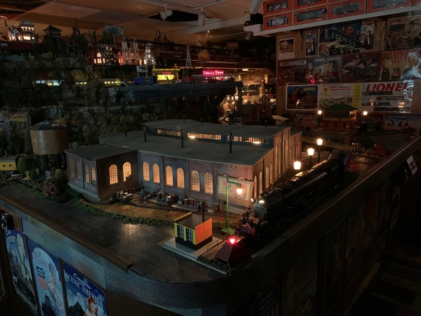
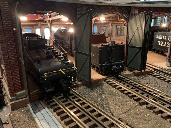
Got the Roundhouse completed this weekend and mounted on the layout and got the lighting hooked up. This weekend was getting the roof panels, smokestacks and doors installed and finishing the interior detail work. I have a few more accessories and figures to go inside that haven't arrived yet. The roofing and doors were weathered before installation and the door hinges painted a brass color. The three front roof panels are joined together and remove as a single panel for viewing purposes and the three rear ones do as well. I'm considering making clear plexi or lucite roof panels, but that would be a project for another day.
 
I think the combination of old-fashioned green hanging LED lamps and hidden LED strips running off 14 acv accessory power provide sufficient lighting and the wiring is basically invisible unless you are looking for it. The flooring, scrap loads, generator, compressor, pulleys and wall shelving were all hand painted, weathered and dullcoated.
 
The addition of steel rods into the tops and bottoms of all 4 corners and the flooring, plus gluing the wood beams into the interior as part of the structure (rather than just sitting there) all made it pretty strong - it's solid as a brick and easily moveable. 
 
The pink circle in the pic's is the size and approximate location of the 24" Millhouse TT.  I'm using Gragraves flex track for the whisker tracks, so they will be straight in the roundhouse, but bent to meet the TT head-on.
 
This was a two month off-'n-on project and, although not for the timid, I would highly recommend it for those that have the room and basic modeling skills and tools. I would guesstimate I have about 75-80 hours into it. If anyone is in need of tips and methods to getting it built, I would be more than happy to share those with anyone that asks and I also want to especially give a shout out to the people on the Forum for helping me out - Thanks !!
 
RH INSTALL 1RH INSTALL 2RH INSTALL 3RH INSTALL 4RH INSTALL 5RH INSTALL 6RH INSTALL 7

Attachments

Images (7)
  • RH INSTALL 1
  • RH INSTALL 2
  • RH INSTALL 3
  • RH INSTALL 4
  • RH INSTALL 5
  • RH INSTALL 6
  • RH INSTALL 7

Add Reply

Post

OGR Publishing, Inc., 1310 Eastside Centre Ct, Suite 6, Mountain Home, AR 72653
800-980-OGRR (6477)
www.ogaugerr.com

×
×
×
×
Link copied to your clipboard.
×
×