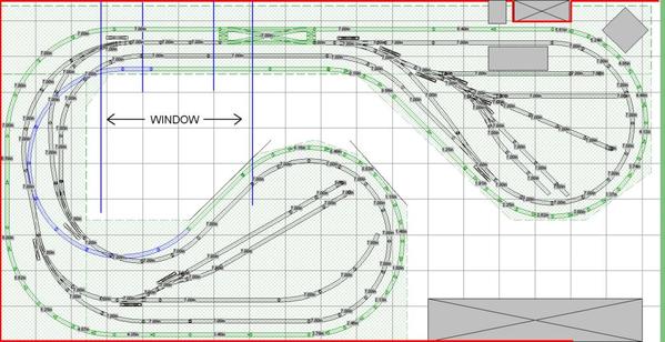
Hello OGR forum.  My name is Chris and this thread is intended to show the progress of my first “permanent”, semi hi-rail layout.  First the track plan.


cjbsrjrrr_r2d_final


This part was not easy.  Of course, I had plenty of features that I wanted to incorporate that simply just would not fit into the space.  Giving those up was the hard part.  Basically, I gave up the larger radius curves (072 and above), a yard area, and a large diesel service area.   I settled on keeping two train operation, the ability to change loops in either direction (double crossover), reversing in either direction, and some sidings to support industry / business in the center of each dog bone end.  The “dog bone centers” are not final yet, but I believe the lower one is close.  Generally, I am happy with this plan.  It’s a lot of track for the space, but that is a compromise that I am willing to make in order get the features described.  The smaller radius curves should work fine for the equipment that I have (for now!).  I prefer modern diesel power and rolling stock.  I am not ruling out a steamer, but if I would own one, it would be on the smaller side.  With that said, you can see am willing to bend the “prototypical rules” in the layout world.  Mostly, I plan to stick with modern theming, but that will be a general guideline only.  Many parts of this layout will be first attempts, especially with the scenery.  That is why I described this as “semi hi-rail”.  I intend to incorporate hi-rail technics whenever possible, but I imagine some elements from the toy train world as well.  For instance, with my current skills I can guarantee that my engines will not be weathered.


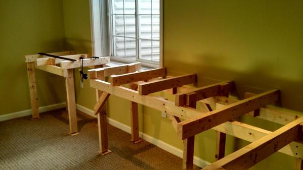
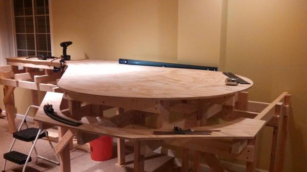
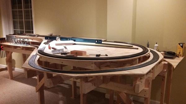
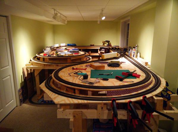
The pictures below are of the benchwork construction of the first half and the start of track laying.  It is mostly 2x4 construction for the simple reason that that is what I had to start with.  Thank you, laidoffsick for posting your benchwork pictures.  Much of my framework design came from those pictures and I have to say it works very well with 2x4s.  In these pictures, I also started laying the roadbed.  I am using Woodland Scenic foam roadbed and foam tack glue.  So far, its working great applied directly to the plywood.  I have been splitting the roadbed in half for the curves and tack it with wire brads until the glue sets.


Some other notes:  The track and switches will be all Atlas O.  Coming up, will be my first attempt at track weathering and ballast.  The layout will be entirely command control.  MTH DCS will be the only system for now.  In the pictures, you may have noticed the empty span in front of the window.  The window is meant for egress, and for that reason I am planning lift out sections in front of it.  How I finish this part is still up in the air.  For now, I will most likely build something temporary just to get the trains running.


That’s it for now.  Before the next post, I want to finish laying track on this half as well as begin framework construction on the second half.  Thanks for looking.


IMG_20131027_150722_962

IMG_20131027_150732_907

IMG_20131027_150740_780

IMG_20131102_113230_554

IMG_20131102_120753_008

IMG_20131113_214847_335

IMG_20131209_211608_443

Attachments

Images (8)
  • cjbsrjrrr_r2d_final
  • IMG_20131027_150722_962
  • IMG_20131027_150732_907
  • IMG_20131027_150740_780
  • IMG_20131102_113230_554
  • IMG_20131102_120753_008
  • IMG_20131113_214847_335
  • IMG_20131209_211608_443
Last edited by MrAnderson
Original Post

Replies sorted oldest to newest

Chris, I totally get the dissatisfaction with having to compromise, but I like the design you've come up with. I especially like how you worked in the reversing loops without making them stand out. I also like the way you used the large loops as grades to the upper (main) level, I never thought of doing that. I've been preoccupied with having 2 complete levels connected to each other and have worried that much of the lower level would be hidden. Using much if it as a grade makes so much sense. Any chance you'd post the rrt file for further study? I'd like to play with the simulation in RRT v5 and see what ideas I could adapt for my layout.


As I work on a design for my 12x13 space, I've been wondering how much I have to stagger my multi-level curves. I see from the photo of the wall that I've been looking at overhang the wrong way. I've been concerned about the ends of cars hanging out too far on my O54/O42 curves, but I see that I only need to worry about the inside overhang, which is much less problematic. I just looked and I see that I could put a wall almost right next to the roadbed on my Christmas RealTrax O31 layout. I realize that the O42/O54 curves I'll need to use are designed with enough separation in mind, but I'm considering bending custom curves. After viewing the "How To" for bending GG flextrack that was recently posted, I think I might be able to do it.


I also like that your photos show HOW things are being done. I can clearly see why you split the roadbed on the curves. The end of the curve in the photo showing the loop being laid is exactly the point that worries me most when considering DIY. I also don't know how I missed noticing how "laidoffsick" did his benchwork because I really like how it's done. I'll have to look through his posts to find it. I see it's 2x4's, but it looks like it would readily adapt to 1x4's or even 1x3's, if I decide to go that route. Mine will be on carpet too and I like the use of small pieces under the posts for leveling. It doesn't look like it's attached to the wall, is it? Did you put some roadbed on the ends against the wall as a cushion?


You can bet I'll be watching this thread for updates. Thanks for sharing. And thanks in advance if you decide to add the rrt file to your post.

I like your design.  I am in the same boat with my new future layout,(we tear down our old layout in about a month).  I have been stock piling Atlas o for the new layout.  The only difference is we have just enough room for our outer lines to be O-72.  I like your design and would like to incorporate it into our future.  Thanks for sharing and looking forward to seeing the progress work.  Nick  

Nick and Dewey:  I envy the fact that you are using/planning larger diameter curves.  This was the hardest item to give up.  I tried and tried to keep them in my design, but it always ended up over complicated and even more cramped than it is now.  I’m glad 0-63 exists in Atlas sectional track.  For my space 63 allowed to me to squeeze in a bit more curve which should help the larger diesels appear a little more “at home”.  Nick, be weary of the isle space in this design.  It requires a bit of a shimmy to get to the center.  To me, it’s a reason to keep my own diameter down.  Dewey, thanks for posting the pictures, the current layout is looking great.


DoubleDAZ:  I attached the .rtt to this post.  Be careful with that overhang.  I have a 4.5 inch or greater center to center spacing between the curves.  I laid out the track on the plywood and tested with my largest equipment (auto rack, large passenger car, ES44) before cutting.  I checked the overhang towards the outside on the inside curve and the overhang towards the center on the outside curve.  Basically, take your largest rolling stock and engines, put one on each curve, and move them back and forth past each other to ensure no collisions.  4.5 worked great for me but with the grade I had to consider any scenery between the levels.  Well, it’s going to have to be thin!  My spacing to the wall is roughly 2.5 inches from the track center.  Again, this is tight.  It works with my equipment but does not leave much room for scenery.  All that said I enjoy these challenges.  I did not attach to the walls, and did not use a cushion but that is a good idea.  Actually, attaching to the walls would have made more sense for the benchwork, but I didn’t do this just in case the whole thing needs to move.  The legs have leveling feet that sit on top of those plywood squares.  I can’t recommend the leveling feet enough.

Attachments

Originally Posted by MrAnderson:

DoubleDAZ:  I attached the .rtt to this post.  Be careful with that overhang.  I have a 4.5 inch or greater center to center spacing between the curves.  I laid out the track on the plywood and tested with my largest equipment (auto rack, large passenger car, ES44) before cutting.  I checked the overhang towards the outside on the inside curve and the overhang towards the center on the outside curve.  Basically, take your largest rolling stock and engines, put one on each curve, and move them back and forth past each other to ensure no collisions.  4.5 worked great for me but with the grade I had to consider any scenery between the levels.  Well, it’s going to have to be thin!  My spacing to the wall is roughly 2.5 inches from the track center.  Again, this is tight.  It works with my equipment but does not leave much room for scenery.  All that said I enjoy these challenges.  I did not attach to the walls, and did not use a cushion but that is a good idea.  Actually, attaching to the walls would have made more sense for the benchwork, but I didn’t do this just in case the whole thing needs to move.  The legs have leveling feet that sit on top of those plywood squares.  I can’t recommend the leveling feet enough.

Chris, thanks for the file, I'm going to have fun running some simulations.


And I'll certainly be careful with the overhang. It just didn't register that I could put a wall closer on the inside of the curve than would work on the outside, that's all. I totally get the 4.5" dual track separation and, like you, I plan to test fit things.


I'm not going to attach my benchwork to the walls either, but I do plan to add some kind of cushion on the ends just to protect the bedroom wall a little. I did notice the leveling feet, but I didn't think of putting a square piece of plywood underneath. I think I'll probably stick with 2x4s too for added stability since it won't be attached to the walls.


Greg, I finally tested the section of track that uses the magnets and there are no adverse effects to DCS.  The magnets are a few inches below the track and are not extremely strong.  N50 rated I believe.  I got this idea from using a tablet cover.  The cover uses magnets to hold it closed.  Maybe this is a bad assumption, but I figured if they could be used in close proximity to a tablet, then they should be OK in my application.

I see that it has been over a year since I posted an update.  Parts of the thread showing the progress from last year are now gone for some reason.  Regardless, I think that it’s still better to continue this thread rather than starting a new one.  Now onto to the layout update.  I believe that I ended the progress updates with phase 1 completion.  Currently, all phases have completed benchwork, mainline track installation, and wiring.  The first set of pictures shows an overall shot of the layout followed by some detailed shots of phase two. 


IMG_20150807_205017

IMG_20150807_205050

IMG_20150807_205114


The lift out section was the most time consuming.  Initially, I had planned to use only bridges to span the gap.  The idea would be the same as the arch bridge below.  That is using magnets to secure the bridge in place.  The bridge or bridges would need to be custom built and after doing some research I decided to abandon this path.  Instead, I built another section of benchwork that can be lifted straight up.  I used metal shelving brackets (pin side down) to ensure the lift out with sit in the same spot each time.  In my case the lift out will be rarely used, so in my option this solution is “robust enough”.


IMG_20150807_205142

IMG_20150807_205316


IMG_20150807_205232~2


In order to give the lift out some visual interest, I cut out the middle enough to add a stream.  It has a foam bottom with foam retaining walls on each side.   The bottom is painted with latex with scenery materials on top of that.  There is also some “track junk” and tall grass and finally realistic water to finish.   I used three Lionel girder bridges re-painted and weathered to span the stream.  The bridges are salt weathered and let’s just say I went a little heavy with the salt.  I’m thinking about blending some more black in with chalks later.  Eventually, I would like to replace the arch bridge with an inverted truss or something similar.  An inverted bridge on the lower level will not block this scenery as much.


IMG_20150404_194634_599

IMG_20150807_205252

IMG_20150807_205305


With the tracks installed on the lift out and wired to a quick connector, I could finally run trains fully around the layout.  This was a great moment!  Now there are many things to work on with the layout.  First up will be more track weathering and ballasting as well as the walls between the two levels.  Sorry about the poor picture quality.  Thanks for reading.


Chris


IMG_20150807_205400

Attachments

Images (10)
  • IMG_20150807_205017
  • IMG_20150807_205050
  • IMG_20150807_205114
  • IMG_20150807_205142
  • IMG_20150807_205316
  • IMG_20150807_205232~2
  • IMG_20150404_194634_599
  • IMG_20150807_205252
  • IMG_20150807_205305
  • IMG_20150807_205400
Last edited by MrAnderson
Originally Posted by MrAnderson:

Of course, I had plenty of features that I wanted to incorporate that simply just would not fit into the space.  Giving those up was the hard part. 


IMG_20131027_150722_962

I think we've all been there, regardless what size your layout turns out as. The military says that no plan survives first contact with the enemy, and no layout concept survives the first track plan once the room size is taken into account.

Cute pooch in that pic, by the way!

Thank you for sharing your decision process, and documenting your construction!  I'm getting ready to build a similar-sized layout and am facing many of the same compromises. Your photos will serve as a nice reference.   If I end up using O42 and O54, I might have to go a little wider on track spacing, I'm glad 4.5" worked for you.  Thanks again and I hope you and your train buddies get several years of enjoyment out of your new layout!

MrAnderson posted:

Thanks everyone for all of the nice replies!  Al, those red rocks are pink foam boards built using a hot knife.  They still need to be detailed and painted, but will eventually be similar in appearance to the walls containing the stream.


Chris

Hi, Chris!
I think too wonderful your the layout and I have the space similar 17x12.

I would like to request your permission to use your project, so I will change some things.

I try to project but I have not succesly !

Do you had more progress in layout?

Thanks,

Leandro Garcia posted:
MrAnderson posted:

Thanks everyone for all of the nice replies!  Al, those red rocks are pink foam boards built using a hot knife.  They still need to be detailed and painted, but will eventually be similar in appearance to the walls containing the stream.


Chris

Hi, Chris!
I think too wonderful your the layout and I have the space similar 17x12.

I would like to request your permission to use your project, so I will change some things.

I try to project but I have not succesly !

Do you had more progress in layout?

Thanks,

Leandro,

So I take it you are going to build a new Enzo Ville layout.  The old layout looks great!!  Chris did a great job on his here.

Leandro, thanks so much commenting and please feel free to use anything that you see here.  I am happy to help.

I am certainly not making as much progress as I would like.  That is why is has been over a year since I have posted any updates.  Progress is slow mainly because I am doing most of this stuff for the first time.  Unlike my job, my hobby has no deadlines so I don't mind taking it slow.  This is what I have been up to since the last update.

These pictures show progress on a cut stone wall that separates the main level from the grade.  I started with foam insulation board and used a hot knife to cut the stone.  The back side of the board is cut vertically to allow it to bend around the curves. The joints are finished with grout that I had laying around.  Gray latex paint and some black washes to finish.

 IMG_20151116_143359IMG_20151116_143422IMG_20160109_140805

IMG_20160109_140831

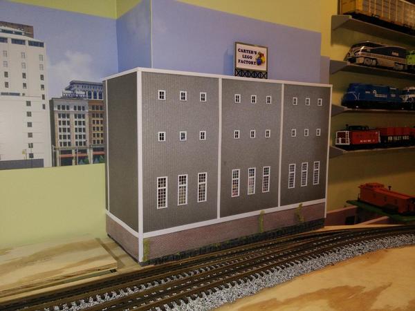
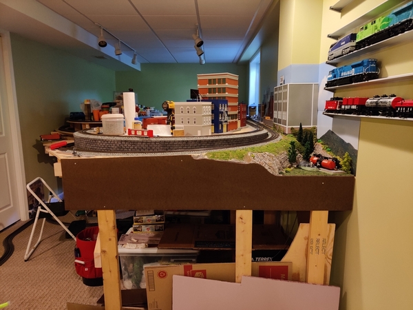
Next I decided that I should finish the scenery on the back wall before finishing the front.  This is because I need to get on top of the layout to work back there.  I had an idea to hide the bump out in the wall with a building.  This is great but I would need to custom build the building.  I have no experience in scratch building but decided to go for it.  The building frame is simply poster board glued to wood supports.  Pattern styrene sheets are cut for windows and painted.  Here are some pictures of the factory building.  I think it came out pretty well for a first attempt.

IMG_20161229_202656

IMG_20161229_203402IMG_20170129_200608IMG_20170129_200646

IMG_20170129_200722

I am planning to start another office type building next to this one.  Once the "hard to reach" sections of the back wall are mostly complete I will start working towards the front.  I am anxious to add a fascia and industry spurs.

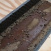
I have a stream made with WS realistic water that poured over latex paint on foam insulation.  Over time the "water" developed air bubbles everywhere.  I will probably rip this out and try again.  Does anyone know if this is due to not properly sealing the foam.

Thanks for looking.

 Chris

Attachments

Images (9)
  • IMG_20151116_143359
  • IMG_20151116_143422
  • IMG_20160109_140805
  • IMG_20160109_140831
  • IMG_20161229_202656
  • IMG_20161229_203402
  • IMG_20170129_200608
  • IMG_20170129_200646
  • IMG_20170129_200722

I just came across this topic ... WOW!  GREAT track plan!      One of the best for the space that I've seen.

A couple of things:

1).  I hope the isolation from the wall is working.  That is so important (in my experience) for sound control.

2). I hope that you have added Legacy - or at least plan to.  It's a great system.     

Chris, Thank you very much !

Your progress is fantastic is correct we cannot have speed in our hobby. I already committed this error in EnzoVille !

This wall was a big idea I did something like with plaster in EnzoVille but with foam the result was better and clean !

My son Enzo loves Lego I will show for his your Lego factory.

Thank you for sharing for us ! I will anxious by new posts !

I have been meaning to post an update for some time now.  I just about fell over when I checked the thread a saw that the last post was over two years ago.  2 YEARS!  Time flies.  Very slow progress over the past two years.  I have been working on small things here and there and will post some more details later.  For now here is a sneak peak of the next scratch built building, CJB Robotics.

IMG_20180802_202121

Thanks for looking,

Chris

Attachments

Images (1)
  • IMG_20180802_202121

Great work and good layout!

I love that foam wall, wish I'd had a justification on my own layout to try that, but it wouldn't fit for me. Looks great on your layout! Might I suggest placing some ground foam into the seams at the lower edges? I've seen that a lot in large block walls like that...

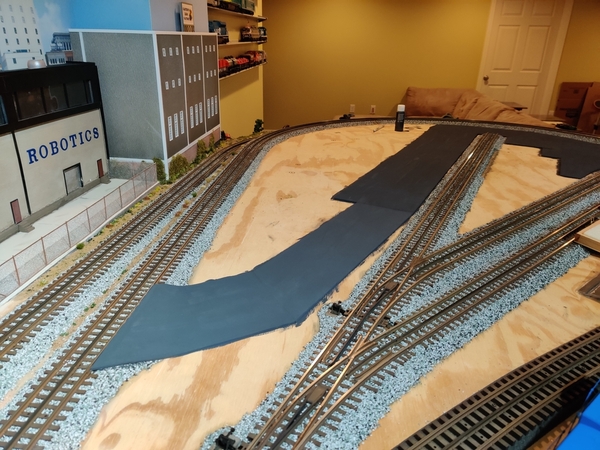
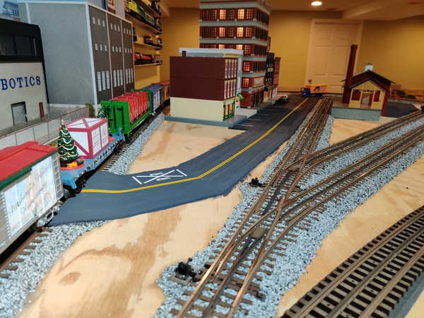
The pics below show what I have been up to.  Mainly the three sidings that will be next to a small town area.  This is not in the original plan.  However, I think this work better than cramming the entire area with track and still gives some of the same functionality.

Note that I decided to use manual throws for the turnouts here.  This was done to save as much space as possible for a road over the “main line” tracks and into the town.  Plus I figure that this will make moving cars in and out a bit more interactive.

 IMG_20191027_182808IMG_20191027_182836IMG_20191027_182852IMG_20191027_183020

Next I plan to weather and ballast the sidings and start the area below.  I am still trying to decide how to shape this corner and blend the terrain with the building (Carter’s Lego Factory) and the wall. 

IMG_20191027_183156

Thanks for looking, 

Chris

Attachments

Images (5)
  • IMG_20191027_182808
  • IMG_20191027_182836
  • IMG_20191027_182852
  • IMG_20191027_183020
  • IMG_20191027_183156

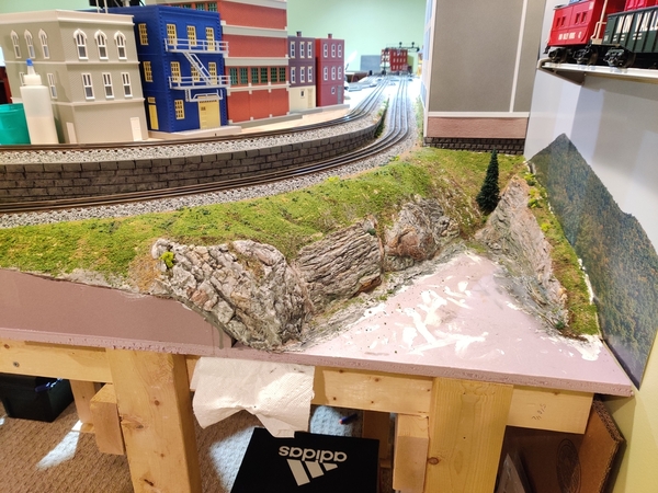
Latest update pictures attached. I have decided to focus on scenery on an empty corner of the layout. Many things were learned here! Basically, I followed the methods shown in Eric Siegel's videos. I would change a few things next time but overall I am really liking the results. The pics below show the progress. It is pretty much complete with the exception of more plant life and debris.

IMG_20200101_150339IMG_20200101_165830IMG_20200331_072525IMG_20200331_072544IMG_20200407_094030IMG_20200410_134641IMG_20200410_134705IMG_20200411_210822IMG_20200411_210837IMG_20200411_210859IMG_20200412_125425IMG_20200526_114818IMG_20200526_114832

Next, I am planning to continue track ballasting and begin fascia installation.

Thanks for looking,

Chris

Attachments

Images (13)
  • IMG_20200101_150339
  • IMG_20200101_165830
  • IMG_20200331_072525
  • IMG_20200331_072544
  • IMG_20200407_094030
  • IMG_20200410_134641
  • IMG_20200410_134705
  • IMG_20200411_210822
  • IMG_20200411_210837
  • IMG_20200411_210859
  • IMG_20200412_125425
  • IMG_20200526_114818
  • IMG_20200526_114832

One goal achieved ahead of the deadline! The "town" buildings are in place and lit. Street markings are also in place. Originally, I intended to weather all the buildings. I may come back to that at some point, but for now I want to make progress.

IMG_20201218_091135IMG_20201218_091213IMG_20201218_091222

It looks like the Christmas train has arrived!

IMG_20201218_091307IMG_20201218_091324

Below is a picture of some remote controlled outlets. These things are working great for powering the layout. I did not want to run wire back to the control panel to power lights. Especially because I intend to have a combination of AC and DC (LED) lights in the future. The remote outlets allow me to power from wall outlets under layout that are closer to the actual location of the lights / devices. The remote outlets that I chose come in a set of five with two remotes. Each outlet can be toggled on and off individually. Science!


IMG_20201218_091536

Thanks for looking,

Chris

Attachments

Images (6)
  • IMG_20201218_091135
  • IMG_20201218_091213
  • IMG_20201218_091222
  • IMG_20201218_091307
  • IMG_20201218_091324
  • IMG_20201218_091536

Add Reply

Post
The Track Planning and Layout Design Forum is sponsored by

AN OGR FORUM CHARTER SPONSOR

OGR Publishing, Inc., 1310 Eastside Centre Ct, Suite 6, Mountain Home, AR 72653
800-980-OGRR (6477)
www.ogaugerr.com

×
×
×
×
Link copied to your clipboard.
×
×