Hi -

I have hoarded 3 AF reverse loop relays in case I need them, I can figure out how to wire the loop itself, it's the wye that's the issue, and how the Wye and loop wiring coexist.  My wye's straight section is on the branch line, the train can enter either direction, run the loop, and turn completely around.  I think it's best to have all these tracks on the same transformer zone, meaning Branch Line and the yard with the loop.  I'd even start with just how to wire a wye - here's my layout.  Note the software can't reproduce my exact layout, but this is close.  "=1" in my terminology means in actuality this is a full, straight section. "=0" means it doesn't actually exist.   (I can turn around 2 SD-90 engines, a dummy, 44 ore cars, and a caboose.)

layout wye


Attachments

Images (1)
  • layout wye
Last edited by milwaukeeroadtrackman
Original Post

Replies sorted oldest to newest

Okay.  Here's what my thinking is. First polarity. There is no "polarity" in AC current. It's like a whipsaw, current goes from the base side of the secondary winding to the hot side, then in the second half of the cycle current ALTERNATES and runs from the Hot side to the Base.  Back and forth, back and forth.  So which rail is base and which one is hot in my understanding does not influence which way the AF engine goes.  I know you can make an armature spin in different directions, maybe that's make use of somehow. Anyway, direction-changing as I think of it is handled by dropping the voltage to zero, having

the reverse unit kick in, then supplying current again makes the engine go in the opposite direction.  So the "danger" in loops and wyes isn't suddenly having the engine change direction due to "polarity", it's from a dead short - see fig 1. When the 2 wheels span the insulator pin you get a dead short.  THAT's what this whole setup is trying to avoid - quickly changing which rail is base and which one is hot without any voltage drop - one that the system can't react to say in milliseconds.

fig1 

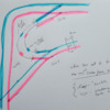
Figure 2 has lots going on. Before the 695 relay is connected by virtue of the insulated pins we've created a dead zone in the loop. Look at the bottom of Figure 2 where the pink (hot) and blue (base) rails are crazy "y's".  The engine is heading into the curved turnout part of the switch toward Pin #2.    When it gets there, we've done 2 things - because the switch is in dual train mode power to track beyond the switch is controlled by the switch itself, so if the switch is set to the turnout then no power goes to any of the track connected to the straight section extending past the switch. So when heading for pin #2, the track has power to the turnout and with the 695 connected the "Initial State" of the dead zone (most of the loop) necessarily matches that of the turnout and the train keeps going without shorting out.  At some point while the engines are in the loop the switch is thrown (later I'll use electronic track trips to do it automatically) then for the engines in the loop which rail is hot and which is base are reversed, note this is no "polarity switch" these peaks and valleys of current just keep on a coming.  What has been avoided is the dead short when the engines reach pin #1.  Okay, next step is to draw the same diagram for the wye ...fig2


Attachments

Images (2)
  • fig1
  • fig2

I suppose I'm the only one on the planet interested in this ... my college summer job for two summers was rebuilding the old Southern Minnesota Division on the Milwaukee Road - 78-79 and 79-80.  I rebuilt the Wells MN wye and want one in my layout.  So I think the "loop" problem and the "wye" problem are different.  With the loop the switch in dual-train mode always "cuts off" power to one rail in the loop, which prevents dead shorts. That's why only one side of the rail needs 2 pins. For the wye, power cannot be limited this way so first off to make a "dead zone" one needs to use four pins.  The diagram below shows how this whole thing might work, as you expect, for 2 of the switches there is no need for any special wiring. It's the one with the dead zone, and "switch action" can't help here because the loop was a special case because there was only the one switch.  So, if you get my drawing lingo, there needs to be a signal to flip the base/hot side inside that dead zone.  I suppose just an electronic track trip (most reliable?) could be used - the engine(s) cross into the dead zone where the rail base/hot side match the track the train has just come from, THEN, in the dead zone, the track trip has to fire the relay to switch base/hot side to match the track the engine(s) will soon reach.  I'll have to understand the 695 loop better, maybe the track trip can fire off whatever the "changing switch position" fires off for the loop.  I'll have to actually hook this up and try it, for this I kind of had to try and do some research ... I can find no WIRING diagram for an AF wye ....    why wye

Attachments

Images (1)
  • why wye

It is possible to wire these using a 695 but as you see it can get complicated. The easier way to do this is make all these sections independent blocks and power them through an AC solid state reverse loop controller. These sense when a power consuming item enters the block and automatically set the supply leads correctly. I have 4 reverse loops on my layout and can say they work flawlessly. 


Here is a picture of one of the boards.IMG_2687

Attachments

Images (1)
  • IMG_2687

MILWAUKEEROADTRACKMAN

I have two of these reverse loops on my layout using American Flyer turnouts. I would recommend the solution Carl Tuveson has illustrated on his website. I used this on both loops and they work flawlessly. The relays you have now will do the job but Carls' solution is simple and inexpensive. The Atlas relay sells for under $15.00 and works so fast the reversing unit in Flyer engine does not drop, you will not even see the headlight blink.

I need to mention this will work if you run AC power, it is not a solution if you run DC power

Last edited by Rayin"S"

This is "wye" I run 3 -rail. Dallee Electronics makes an AC auto-reverser board, also. I pointed to the NMRA DCC wiring article because the concepts are the same.

The point that is different from your wye than those readily found on the internet is that the "tail" on your wye is not isolated like a point to point track plan with a wye at an end or at a customer stop.

A section is needed to move the tail electrically  or perhaps isolate all three and only align the polarity for the switch pair combinations. Like another set of gaps on the main, between the switches, added to the attached diagram with another reverser board.

perhaps a call to Dallee would help.


Attachments

Images (1)
  • 2 Rail wye wiring

Carl, I like your reasoning of wye you are a 3 railer!

The wye is simple with the auto reverser board. Only one is needed. Referring to Milwaukeeroadtrackman's wye sketch, use gaps in both rails near SW2, eliminate the gaps as shown near SW3, add gaps in both rails near SW1 similar to those at SW2. Finally add gaps in both rails to the right of the 690 track terminal and power that terminal from the output of the board. 

One additional board is required for the reverse loop shown in the complete layout plan. Once wired up just run the trains wherever desired. The reverse loops take care of themselves, just like it was a 3 rail layout! All this assumes AC power is used. 

My layout is powered with two ZW-L's and uses the Legacy control system. The only additional components I have are some small capacitors to put the legacy signal on both rails and get it across the isolation gaps.

Like MILWTRman - and others - I've also stashed a couple of the Flyer reverse loop relays for that day in the future when I might want to have a reverse loop or wye.  But based on Tom's note, I looked up (meaning Googled, of course) PSX-AR-AC which led to the board in question.  Looks to me like this is really worth considering - making the assumption that one doesn't have to be running DCC to be able to use this board.  Here's a link to the manual (always a good place to start).  You will note there is an explicit discussion of application to a wye.  I know essentially nothing about these boards and there's a lot of detail - including some programming ability (not required, apparently) - in the writeup,  but this could be the modern day answer to a maiden's - errr, electrical (or railroad) engineer's - prayer...

http://www.dccspecialties.com/...ts/pdf/man_psxar.pdf

I also note - again with absolutely no experience with it - the board has some other features like train detection, etc.  At ~$45, seems like it might be a relatively low cost 'answer'.

- Rich

Rich, the instructions linked above are for the DCC version. For some reason the AC versions I have are not listed on their website. There is really no need for the programming in AC and Legacy layouts. I am traveling this week. When I get home I will look to see if I still have a copy of the AC instructions.

Be careful setting up the wye. My description above will work with Gilbert turnouts. I believe the one in the linked instructions assumes scale turnouts with insulated frogs are used. The frogs are then powered from separate relays (as mine are) or in a DCC layout the DCC boards can flip the frog power if Tortoise machines are used. 

If you look at the picture I posted above, the AC board is quite different and has a very robust heat sink to handle 10A from the ZW-L or similar transformer. 

Tom - I assumed - perhaps erroneously - that the instructions were generic to the PSX-AR series of boards.  Again, no direct experience on my part...

Here's what they say is their -AR product line (copied from a section of the product page):

(1) PSX-AR, with integrated stall motor decoder
(2) PSX-ARFB, same as above with added network feedback
(3) PSX-ARSC, with integrated snap coil decoder
(4) PSX-ARSCFB, same as above with added network feedback.
(5) PSX-AR-AC, same as above but designed to work on conventional 2 rail AC.

I did notice that the board picture you provided does seem different that what is shown in the manual.  Its probably worth emailing the dccspecialties folks and ask them specifically about the board capabilities when used with "ordinary" 2-rail AC and Flyer currents.

- Rich

This is good discussion ... give me a couple days to study this.  I plan on having an Alco ABBA both-A's powered so I'm trying to enlarge the two wye entrances from the secondary oval, I figure those entrances have to hold all the powered units along with a little spare room on each side no matter the solution ...  I do have the C shaped current trips and also the small silo current trips - one set is to automate the loop switch and the other can be for the wye, I suspect I'll need another set ...

A couple of thoughts on automatically throwing turnouts. The PSX board will operate a Tortoise machine, I do not know if they will operate a Gilbert turnout. That would have to be verified.

I do not use the automatic turnout feature because it is too likely that a different train could be running over the reverse loop exit turnout when a train enters the reverse loop. This is similar to using the Route feature in the Layout Control System (LCS.) I built Route macro's but some of them throw up to 7 turnouts to set up the route. Invariably a train was positioned over at least one of the turnouts so I find I never use those macro's. 

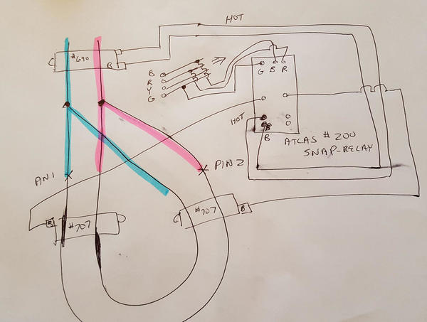
So I began hooking up the Atlas - with the connections made to the loop switch the relay moves back and forth in slave mode with the switch - fine - but when I add the connections to the Atlas from the track it creates a huge current draw, the transformer circuit breaker doesn't trip but the switch controller bulbs go out and the hum of the transformer ceases ... I guess I need a different wiring diagram ....Image2

Attachments

Images (1)
  • Image2

Hi -

The small error in the wiring diagram is not the problem - it was something I did.  Now I've had an AF 695 reverse loop relay running the loop, it's just a big coil relay. There's a "core slide" that needs to be cleaned so operation is smooth and also one small area of circuit board must slide along another and these two sliding areas are metal contacts so there's a lot going on ... a friend who used to clean old movie theater projectors told me use good clean typing paper to clean the contacts and coil plunger, I'd say using AF tech the switch was reliable thrown 90% of the time.   Issue was "controller slop" and "misfiring" of the switch itself.

With the Atlas it seems I'm having other issues - mainly this particular switch isn't travelling fully all the time.  There's a relay in the switch to throw the tracks, can that be cleaned?  I've never dis-assembled one.

Also, for zones, as soon as the engine hits the insulating pins it stops even though I've hooked up light bulbs to show me that power is there on the other side.  AF only insulates one rail in the loop and uses two train operation setting on the switch, I'll see if I can do this with the Atlas ....

In the diagram, is the switch set for single or multi train?  I wouldn't think it mattered, jus askin .....

My layout is on 1/2 inch plywood set upon two by fours on their sides on my bedroom floor. So I can't get under a table to run wire, so that means I have to figure out the wye and loop wiring on non-nailed down track, then take it all up, take up the plywood, run the wires (screw terminals to connect between 20 switches and the controllers etc., yes, I know that some switch pairs can run off the same 1/2 of the controller, so 2 controllers can AF with atlasrun 8 switches) 

So sorry this is dragging on.  Okay, this wiring works - the engine runs across the switch and into the loop, now I have to clean the loop track and finish testing - here's my crude diagram

Attachments

Images (1)
  • AF with atlas

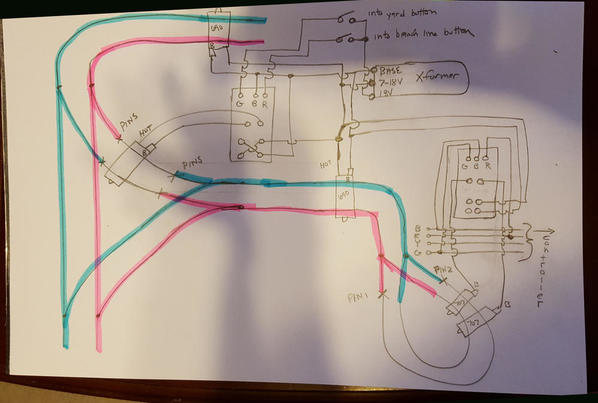
Okay - here's my "low tech" solution - Right now I've done it using alligator clip wires, I have yet to do the full test, but each half works.  The loop depends on the loop switch itself to switch the rail "polarity", in my wye the two switches have been set up to "run into each other correctly" so their's no "trigger" to switch things when the train is inside the insulated section.  Plus we'd need to detect the 2nd trip, and how to do that doesn't occur to me just now. I'm using push buttons to energize the #200 snap relay.  I tried a couple track trips, the one with the shoe, a canister type too, but these SEEM TO ME to "sink", that is, some black box (AF action device) is hot and the wire that goes to the track trip provides the path to ground, meaning there's no "hot voltage" to use for control.  I'm trying to see if the old 670 track trip might work, but I bet not.  The track trips seem to be used for the way I wired the loop with only one rail using 2 insulating pins, when I try it with the 4 insulating pins in the wye it works fine one way but when going back the  26671 shorts out because it was on the base connection to the transformer and now it's across the hot rail (the instructions say it's to be connected across the two zones).seemsgood

Attachments

Images (1)
  • seemsgood

FINAL

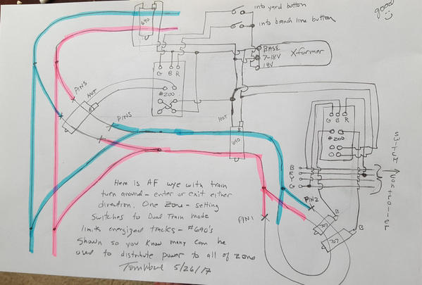
Here is a slightly corrected final diagram. I did not hook the loop and wye together for a test, but each section can use the same #690 power clip orientation so I'm assuming things will work.  My large outer loop is on one side of a dual transformer, the rest of the track is on the other. I will use #690's every 10 feet or so and with dual train set on some of the branch line and yard switches meaning a good portion of this zone won't get power at any one time, that should allow this low-tech layout to work.  Note only one leg of the wye is "a problem" and I re-did the layout so that the "problem" leg has greater length - enough to use and Alco ABBA or perhaps an ABBBA even - I love B units.

I hope someone else gets a kick out of this and adds a wye leading to a turning loop, now I can operate and turn trains and send them out in any direction.  The caboose track?  Engine brings caboose from engine yard and drops on caboose track. Then picks up cars, pulls out, backs into caboose track, and hooks up.  To return cars toImage69Image70 siding, turn around on loop, back up, drop caboose, then drop cars, fetch caboose, return to engine yard.  Anyway, someone suggesting the #200 snap relay really helped.

Attachments

Images (2)
  • Image69
  • Image70

Add Reply

Post

OGR Publishing, Inc., 1310 Eastside Centre Ct, Suite 6, Mountain Home, AR 72653
800-980-OGRR (6477)
www.ogaugerr.com

×
×
×
×
Link copied to your clipboard.
×
×