My Lord! Things actually went smoothly today!

I hooked up three DZ-1011 dwarf signals through 1008 relays to indicate turnout position. Plus the last two switch machines were wired. Everything works (see circuit diagrams from 2-19 and the correction from 2-26).

I wired the one dwarf signal to the switch motor previously wired just to make sure the connections were correct.

Prescott Layout 004Prescott Layout 005

I then wired the other two switch machines made sure they worked then their companion dwarf signals. Everything works just fine.

Prescott Layout 007

Because the 4-way was moved to a new position as mentioned earlier I had to move terminal boards under the layout to accommodate the new position. As a result almost all wires from the switch motors and the dwarf signals were too short. I am not much on soldering so try to avoid it as much as possible. To splice wires together I use a combination of wire ferrules and crimp splice connectors. My process is shown below.
Note I am using 22 gauge wire which is way too thin for the normal red crimp connector plus I never liked crimping a bare wire into a connector. They too often pull out (probably my technique).

I first crimp the wires with 22 gauge wire ferrules (blue)

Prescott Layout 001

These ferrule are too small for the standard red crimp connect but an 18 gauge ferrule (yellow) fits snugly. So I  crimped the 22 gauge ferrule into a 18 gauge ferrule.

Prescott Layout 002

I then crimped the ferrules from the two wires into a standard splice connector. These wires are going no where.

Prescott Layout 003

Attachments

Images (6)
  • Prescott Layout 004
  • Prescott Layout 005
  • Prescott Layout 007
  • Prescott Layout 001
  • Prescott Layout 002
  • Prescott Layout 003

Got some more work done on the yard. Spent most of the day placing track and roadbed. I had to cut some track to make the yard cross overs work. I also soldered wire to four tracks that will act as non-derail track for the 4-way. While not strictly necessary for the yard I think the non-derail is cool and is too easy to wire so why not............

A picture of the yard - already see where I screwed up. Luckily the track is not wired or screwed into place as yet. I envisioned the far yard cross over as a round around but allowed only 10 inches behind it. I am going to need to move it up another 10 inches - no big deal.

Prescott Layout 003

This is shot of the Gargraves and Atlas O De-coupling track.  Given the bar's lenght The Gargraves is definitely going to be easy to cite cars on.

Prescott Layout 004

I needed to place the Atlas O De-coupling track in-between two Ross tracks but could not use the Atlas O to Ross track pins. Below is a picture of the underside of the Atlas o track. As can be seen three of the four track joiners are soldered to the track.

Prescott Layout 001

So I attached a 1.75 inch Atlas track to one end and was fortunate that I had undercut the Ross track at the other end to receive Atlas joiners. So on one end I have the Atlas O to Ross joiners and normal Atlas O joiners on the other end.

Prescott Layout 002

Next W/E hopefully I will wire all the track for power and the attach the wires for the non-derail feature.

Joe

Attachments

Images (4)
  • Prescott Layout 003
  • Prescott Layout 004
  • Prescott Layout 001
  • Prescott Layout 002

Did some work on the yard this Sunday. As mentioned in the last post I had to move one yard cross over up further to allow enough room for a locomotive to back up into the next yard lead. It took some maneuvering of track and some more custom cutting track to length. I cut roadbed to fit then added power lines to all track (that's the mess you see in the second photo) and will connect to terminals next weekend. Then hopefully it is on to connecting the cross overs and non-derail features for the 4-way. After that connecting the decoupling tracks.

I also have been making sign posts (got this from a job I did for a customer) that designate the turnout number to coordinate with my control board. I think it is much better to say 'park the box cars on siding #5' rather than 'the fourth siding from the right'.

Prescott Layout 001


Prescott Layout 002

Attachments

Images (2)
  • Prescott Layout 001
  • Prescott Layout 002
Model Structures posted:


...

Prescott Layout 002

Next W/E hopefully I will wire all the track for power and the attach the wires for the non-derail feature.

Joe

Do NOT use these joiners to join Gargraves/Ross track. Thermal expansion/contraction can cause gaps and/or gauge shift to form. You're better off filing/cutting out the webbing on the bottom of the Gargraves Rails and using regular Atlas track joiners. The design was a good idea, but if your layout environment is subject to changes in temperature and/or moisture you can get separation problems.

Matt:

Thanks for the heads up.

I have the layout in a spare room in my house plus I screw down all track. Hopefully this will alleviate the issue. But I will monitor and see if anything happens. One thing I did notice. The joiners are pretty flimsy. Once inserted they will break if you need to remove for any reason.
The yard will be the only place I use these joiners. Everywhere else (especially the main lines) when I go from Atlas to Ross I will use the undercut method you mentioned. Since I am screwing down all track I have been thinking about just butting the ends together w/o any joiners at all. Power / ground will be connected on both sides. This method works for isolated ground track plus going form one power break into another. Your thoughts Matt?

Finished up laying track plus ground/power in the yard. Next W/E I will wire the non-derail and the two cross over turnouts. I have one track that doesn't look straight which I will have to fix plus for some reason the switched spur all of a sudden does not turn on so I will have to figure out what is going on there (probably pulled a wire loose crawling under the layout).

A while back I bought four cheap LED dwarf signals from Hong Kong (see photo below). I am going to try these with a DZ-1008 relay and see how they go. The signals come with a resistor attached so it should be a straight hookup.

I also bought a Gargraves gantry track (see photo). I had already built a gantry that would ride on rails however as you can see it is too wide for the Gargraves track. My plan is to use the existing gantry up front and build another one that will fit the Gargraves track.

Various 001

Various 002

It is hard to see but the dwarf signal is towards the middle of the photo.

Prescott Layout 001

The new Gargraves gantry track

Prescott Layout 003

My gantry is too wide for the gantry track so I will use it either up front or in the back depending on fit.

Prescott Layout 004

Attachments

Images (5)
  • Various 001
  • Various 002
  • Prescott Layout 001
  • Prescott Layout 003
  • Prescott Layout 004

Looks like my ambitions were bigger than I thought.

I fixed the issue with the spur not turning on. My diagrams said it was spur #2. My wiring said spur #8. Both now match as spur #2.

I also discovered one of the turnout indicator lights was now working either. Turns out the wiring runs over the pull out control panel and pulling out the drawer also pulled out the wires......... so I spent time re-routing and fixing this issue.

I did manage to drill holes for the turnout wiring and associated lights and crimp on ferrules in preparation for wiring next weekend. I have shown my system before but will repeat here. I am not much of a fan of soldering so use a method that involves wire ferrules whether they end up in old fashion spade connects or simply insert into European style connectors. since the wires for the switch motors and lights are very small I first crimp them into 22 gauge wire ferrules  ( the little blue ones) which fit very nicely into 18 gauge yellow ferrules. These in turn will fit into any 'red' standard crimp connect. To add more wire to route to the terminal connectors   I crimp the 18 gauge ferrules into red butt splices. This technique works great for me and gives a super strong joint.

I also discovered that the yellow 18 gauge ferrule will fit into 'push-in wire connectors (see last 2 photos). These connectors come in 2/3/4 and probably more ports. They are basically shorting connectors. So you can connect 3 wires from three different accessories to the connector and use the 4th wire to go to a terminal.

Prescott Layout [2)

Prescott Layout [1)

Prescott Layout 001Prescott Layout 002

Attachments

Images (4)
  • Prescott Layout (2)
  • Prescott Layout (1)
  • Prescott Layout 001
  • Prescott Layout 002

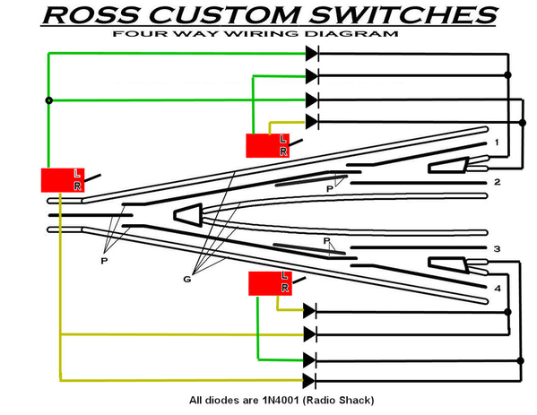
Didn't post anything for the last week because what I attempted did not work. Even though not strictly required I had the isolated track so decided to make the 4-way in the yard non-derail. This should have been easy enough to do (I did it before) - see picture below

4way-with non-derailing


Well I hooked up everything and NOTHING WORKED!
Tried various combinations of wiring for about two hours then gave up. While eating dinner I had an A Hah moment. The switch machines have their own power separate from track power which means separate grounds. So the next day I made both grounds common, declared victory and tried the non-derail.  Needless to say NOTHING WORKED!
So this W/E I will move all the wiring/terminals to the top of the layout where it is much more comfortable to work and figure out what is going on.  I know these scheme works since I have done this before so I figure a simple routing error somewhere.

Having fun
Joe

Attachments

Images (1)
  • 4way-with non-derailing

Joe,

One of the diodes needs to be reversed consistently - choose the same direction for the all of the L's and all of the R's. They are only needed to prevent the controller lights from flickering. All in the same direction will stop the current flow.

Z-Stuff DZ-1000 for non-derail

I like the way Ross suggests a 3" spacer track between the switches for the 4-way yard . I use that for power control and the non-derail trigger rail. It looks like you could move that point to the track after the switch end - the two short center straights and the two outsides curves to parallel.

Dan - thanks. I'm going to keep the common ground. It's a good idea. Yep the red boxes are the switch machines. 

Carl - I was wondering. I had the diagram you gave the link for plus the diagram I got from somewhere. I will try reversing the L diodes before I go into the shop today.
I am also using 3" track on the inside straight portions but opted for making the curved transition track on the two outside portions of the 4-way due to lack of space. On all other Ross turnouts I am using the 3" track. It is so much easier to use plastic pins on the ends of the 3" then cutting into rails and filling with silicone.

Joe

Spent all day working the ground issue to no avail.

I have three power districts powered by two Lionel 180 watt power bricks and one tap (track 2) of the Z4000. Each power source is connected to a Legacy Powermaster then to a common ground under the table. The Turnout machines are powered by the 14VAC tap on the Z4000 with a separate ground.

As long as I keep the ground for the turnouts separate from the power district ground the track voltage and turnout machines along with Z-Stuff dwarf lights connected through 1008 relays to the turnout machines work just fine. Only the non-derail does not work since it needs a common ground between the switch machines and track ground.

Just to be sure about the Z4000 I disconnected the 14VAC wires, then shorted ground between the 14VAV tap and track 2 directly on the transformer (ie before the powermasters). The Z4000 acted just fine. As soon as I ran a wire from the 14VAC ground tap on the transformer under the table and connected to ground after the powermasters, track 2 of the Z4000 goes to 12 amps at about 1.2 VAC.

As I said earlier I did have the non-derail working on my previous layout. The only change I made was to switch a new legacy powermaster for an TPC400 that was previously connected to the Z4000.

Joe

Still playing around with the Z4000 - see https://ogrforum.ogaugerr.com/...58#79142442707728458

Based on tracking the common wire last night I may have a potential feedback issue though am not sure as yet (diagrams on the other post).

I sort of declared victory last night and ordered another Lionel 180W power brick. This way I will have three bricks feeding three powermasters and use the Z4000 for switch motors, ITADS etc.

Good! That eliminates one potential problem.

This sounds as if you have a phasing issue between your power supplies. Have you checked that all 3 sources are in fact in phase with each other? Just because they have polarized plugs on the house side does not guarantee they will be in phase.


Chris

LVHR

Add Reply

Post
The Track Planning and Layout Design Forum is sponsored by

AN OGR FORUM CHARTER SPONSOR

OGR Publishing, Inc., 1310 Eastside Centre Ct, Suite 6, Mountain Home, AR 72653
800-980-OGRR (6477)
www.ogaugerr.com

×
×
×
×
Link copied to your clipboard.
×
×