Check the date code on the bottom of the PH180's. There could be an out phase problem if you have an older one. See attached.
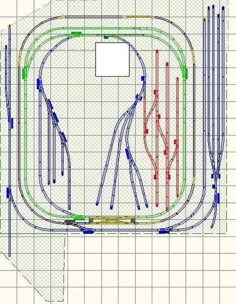
Model Structures posted:As I find time I am building a new layout. The figure below was my 'original' design. I had the yard work wired in then showed my design to a friend who I consider a hi-rail expert. The track module outlined in red is a half copy of John Allen's Timesaver switching game module. My intent was to have something for my friends to do when they came over other then watching trains go round a circle.
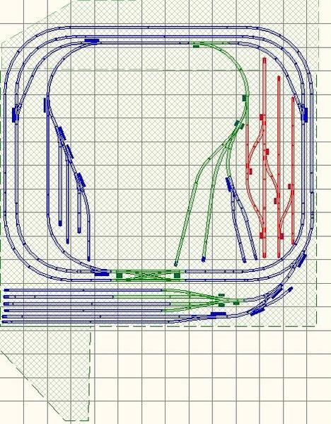
When I showed the design to my friend Peter he pointed out that the Timesaver module was too far inside the board so it would be difficult to place cars where needed to start the game - something I never thought about! Peter made some other suggestions. The bottom line is the design below.
With the new design I should be able to reach in to place cars (furthest track is about 30 inches in) plus I still have the yard where I can reach individual cars to manually uncouple them. Down the road I want to install some turnouts at the end of the yard for an engine run around track.
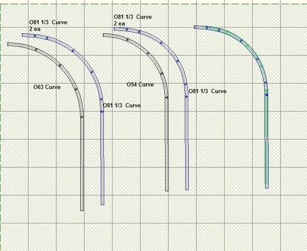
Another good thing about starting over is that I discovered from the reading a John Armstrong book the wonderful world of easements. For various reasons I chose to run O63 and O54 curves on the main lines so easement will come in handy. Since I don't have any flexible track I found out if I use O81 1/3 curves - two going into the curve and one on the end, I end up with the same total curve pattern in area - see below. This is not much of an easement but I think it will still make the trains look better going into and out of a tight curve.
The last curve on the right is actually both the all O54 placed over the one containing the O81 1/3 curves. It is a almost perfect fit. Note this particular track is Atlas O. I started out with Atlas O sectional track so have a good inventory. However for any new turnouts or track I use Ross. A lot of the interior siding and yard work is all Ross. Since Ross does not make partial curves probably the best course would be Gargraves flexible track or cutting down an O81 sectional curve.
Joe
It is a great thing to get great advice. Most people have way too many spots on their layout which are difficult to access. WELL PLAYED! :=)
Moonman posted:Check the date code on the bottom of the PH180's. There could be an out phase problem if you have an older one. See attached.
both are 2014
lehighline posted:Good! That eliminates one potential problem.
This sounds as if you have a phasing issue between your power supplies. Have you checked that all 3 sources are in fact in phase with each other? Just because they have polarized plugs on the house side does not guarantee they will be in phase.
Chris
LVHR
Yep - checked all three - in phase
With the Z4000 out of the loop everything is working. I have wired non-derail for for two of the three switch motors and all is working well. I will wire the one remaining switch motor tonight.
To do list:
1. Re-trace ground circuit and make sure it is ok
2. Wire reaming non-derail
3. wire switch motors for the two crossover turnouts
4. wire dwarf signals for the crossovers
5. wire the four de-couplers (two Gargraves and two Atlas O)
So phasing is not the issue. That leaves your wiring.
Just as a final check, try swapping a brick and the Z4K. If all is well with the transformers, there should be no change in status. Which definitely leads you back to the layout wiring. Somewhere you have to have at least one common and/or hot lead reversed. Can you pull the 4-way completely out of the layout and work on it on the bench? Then you have only one (big) component to deal with.
Spent another 5 hours playing around with the Z4000. I disconnected all track wires. I disconnected all the power supplies then double checked the the power / common wiring to all terminal broads under the table. I reconnected the power supplies and checked voltages at each terminal with the track wires still disconnected. Since the power supplies share a common ground if I had an out phase Z4000 I assume I would see a much higher voltage between a terminal board for the Z4000 and one for the 180W power bricks plus a voltage between the power ('A' or pos) between the Z4000 and a power brick. All was well. Just to double check I turned the power plug for the Z4000 around in the power strip (I have a plug adapter that allows me to do this) and sure enough there was voltage between the 'A' terminals of the Z4000 and the power bricks.
So bottom line I know my wiring is good, I am pretty certain the Z4000 is in phase with the power bricks. If I short grounds ('U') terminals on the Z4000 for the track 1 voltafe and 14VAC before the Legacy Powermaster I have no issues, if I connect the grounds after the powermaster I have issues. If I connect one or the other I have no issues. So I am declaring victory and moving on. I have a power brick on order. I will use this to power the third track district and use the Z4000 for turnouts (common ground with power bricks) and accessories only. I have tried this already and it works.
Next Sunday it is back to wiring track and turnouts in the yard. I bought some LED dwarf lights from a Hong Kong outfit. It will be interesting plying around with these...............
Joe
I owe everyone a huge apology. I must have been testing phase the wrong way. I reviewed Lionel's YouTube video on testing phase and duplicated the light technique. Sure enough the Z4000 is out of phase with the two Lionel power bricks. The light was turning on when connecting red terminal to red terminal from the Z4000 to all three powermasters but not when connecting red to black.
I have a three prong into two prong adapter so used it to turn the Z4000 plug around in the power strip but this did not work for some reason. I tried turning the Lionel power bricks around but then they would not turn on the powermasters.
The one thing Mike ?Reagan's? video otherwise excellent did not touch upon was how to correct two power supplies out of phase with each other. I have a feeling I would need to have someone go inside the Z4000????
I still have a third Lionel power brick coming in, supposedly tonight so will hook it up to the third powermaster. For some reason the 14V terminal if used by itself will work with the power bricks on a common ground. If it does not I have a small Lionel CW40 I can try.
Joe, It is good to know you are on the right track now! ![]()
Joe,
Is the Z4000 healthy? Throttles ok and such? Has anyone ever been inside for repairs? It shouldn't be out of phase, even though it's a strange beast to me.
I didn't like because it wouldn't turn on track power with the throttles preset.
Shoot an email to GGG and see what he thinks of this.
Moonman posted:Joe,
Is the Z4000 healthy? Throttles ok and such? Has anyone ever been inside for repairs? It shouldn't be out of phase, even though it's a strange beast to me.
I didn't like because it wouldn't turn on track power with the throttles preset.
Shoot an email to GGG and see what he thinks of this.
As far as I know it is ok though it is old - 2007/2008????). No one has ever touched the insides.
By GGG do you mean Gunrunner John?
I just received the 180 power brick. I will install tomorrow. I have the CW40. If it will power all my turnouts and dwarf signals then the Z becomes a boat anchor and goes sup for sale.
The new 180W power brick arrived. I replaced the Z4000 with the power brick for Track 1 plus I installed a CW80 (thought it was a CW40) for accessories. I programmed the accessory voltage for 13 volts (pretty cool add-on by Lionel!) to power the various turnouts switch machines plus all the dwarf signals. Got a photo of the revised power drawer below.
I tested the three power bricks and the CW80 with the lamp and everything checks out. So all track wire plus the non derail wiring was re-connected. As Mark said - I am back on track again. I have non-derail working for both the forward two switch machines on the Ross 4-way. They work fine however when I try to connect to the non-derail to the approach switch machine the other switch machine points start to flutter so I need to do some more thinking here.
I also tried the non-derail with and W/O diodes and could not tell any difference in performance nor the lights so stayed with wire only. I wonder if this has to do with the flutter????
I barely mentioned I had a Z4000 'boat anchor' and a friend magically showed up and took it for his layout. I did contact MTH via their web page email about a week ago. So far no replies.
Joe
Attachments
Went back to the non-derail issue. But first I discovered that two outside rails coming off the Ross yard crossovers were isolated. These two rails are between the crossover and the intentional isolated rails for the non-derail feature. I broke a cardinal rule of mine (always wire track power and ground on each end of a turnout) because this track was sitting on top of my control board and I did want wire running over the area of the board. I had to take up a lot of track to fix this but it is done.
Back to the non-derail. I have the basic wiring done. I can control the two outboard turnouts with the isolated track now. However as soon as I add the entry turnout into the wire scheme a lot of weird things happen - flutter, the entry turnout switching when I use a toggle switch control wired to one of the outboard turnouts. So next week I am going to remove the wires for the dwarf signals (they are connected to DZ1008 relays and ultimately to the turnout machines) and see what happens with the non-derail.
Attachments
Some stuff happened last week so this entry is really for last Sunday. I could not get the non-derail to work for the entry turnout and finally figured out why. When I first wired the 4-way in the previous design I used 2 toggle switches connected to the left and right outboard turnouts. Each toggle switch in turn was connected to the entry switch in the appropriate direction. This time I wired in 3 toggle switches - gave the entry turnout its own switch. So if I tried to wire non-derail for an outboard and the entry turnout I created a back-feed which made the outboard turnout flutter. I am going to change this during the week.
Meanwhile thinking I was out of the woods (yea right) I used a small lightweight caboose with lights (I use this to make sure track power is on when wiring track) to test the non-derail but also sent it all the way through the crossovers. The bottom crossover worked just fine. However going through the curve on the top crossover the caboose kept shorting out and blowing the transformer fuse.
I tried thee other cabooses (cabeese???) with no issues. It was just this one little guy. As I mentioned above it went through the other crossover with no issues so it was not the caboose itself. Well after going through the turnout upteen times looking for issues I starting sending Steve at Ross Custom Switches emails. Steve kept giving me pointers to what to check. It was during the week I was trying some stuff Steve recommended when I needed to use both hands - one for the caboose on one on the track when I noticed the crossover would wobble side to side about 1/16 inch. Background - I don't glue the cork roadbed not do I glue track. I simply screw the track through the roadbed and into the homasote under layer. So I figured what the heck and put a screw smack dab in the middle of the crossover (see below). After four days of head scratching and exercising Steve the caboose started sailing through the crossover with no issues.
Now on to a new adventure. I am actually going to wire these switch machines..............NO NON-DERAIL
Joe
Attachments
Joe, I'm glad you finally got that one! I hope all the head scratching didn't cause you any loss of hair!
No sweat - it is already gone!
I did try wiring the entry switch machine through the toggle switch to the two out board machines. It should have worked but once again nada. to add to my misery I think I blew a 1008 relay playing around with the crossover.
On to more diasters.................
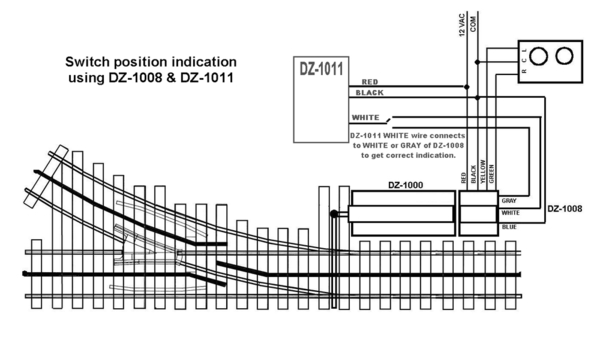
I have been spending the last few W/E's working on the dwarf signals for the 4-way and the two cross overs. I am using DZ1011R dwarf signals and DZ1008 relays. Call this a learning lesson - wire the two exactly according to the diagram D. Zander supplies. I neglected to connect the yellow wire from the 1008 to the DZ1000 switch motor (so only the green wire was connected). The relays / dwarf signals worked great until they did not work anymore. So far I have 3 fried 1008 relays.......................
Attachments
Joe,
How often in my 42-year career in electronics I could have written the same sentence; The ______________ worked great until they did not work anymore. I am glad you found your mistake, before more were destroyed. I do not know if I will put in signals when I get to putting in my stock of Z-Stuff machines, but I appreciate your sharing.
Mark:
Thanks! If you do decide to place signals but don't want the hassle of all the wires necessary for relays the easiest thing to do is hook up the signals to IR detectors. Lionel and MTH make big massive ones. Z-Stuff makes a much smaller version but get the right one - I think it is the 1075. The other one (1070?) only works with Z-stuff signals. You can also eliminate the detectors all together and just go with Z-Stuff signals alone since they have built in detectors. When I use the DZ-1011R with the relay I place a piece of electrical tape over the sensor. If you use any Z-stuff signals with the 1075/1070 you have to do the same thing.
Joe


