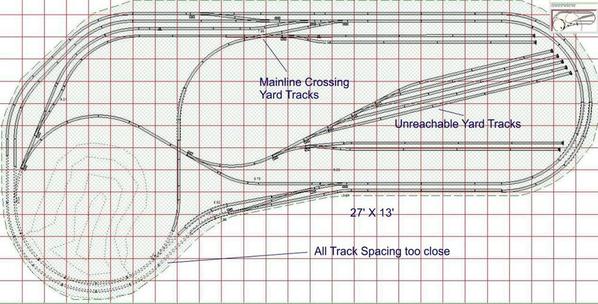
I've haven't started rebuilding the Pennsy and Pacific RR since we've moved to our new home in Louisville, KY. I was sidetracked by building an RC B-17E on commission for an RC pilot and building a museum scale USS Missouri model. Butnow that project is reaching an end and I've been instructed by my wife that I should get cracking putting the trains back together before the grandsons are too old to help or enjoy them. Here's a drawing of the old layout as it was in our Pennsylvania home. It was 27' X 13', two-track main line, min. diameter at O-88 and all Ross trackage. It was conventionally powered with an MTH Z-4000, but no DCS. The RR was entirely L-girder construction using shaped plywood sub-roadbed panels with Vinylbed roadbed. For the move all the ply and vinyl was scrapped.


L1 final


As you can see it had some problems. Using the native track spacing of 4" center-to-center, my ultra-long engines had some intimate love affairs with long cars on the outer loop. Specifically, my 3rd Rail H-8 Allegheny and the MTH centipedes and coal turbine, all kissed trains on the outer track. It did some minor damage to the H-8 and in some cases did worse things. 


The design also had a mainline crossing running through a yard track which meant all trains on that yard track had to be broken in two or they fouled the main. 


Lastly, the big yard tracks were unreachable which made handling trains very difficult. The RR was not senicked. While I was procrastinating this task, it was fortuitous since we eventually moved states when I retired in 2009.


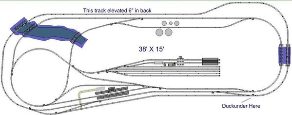
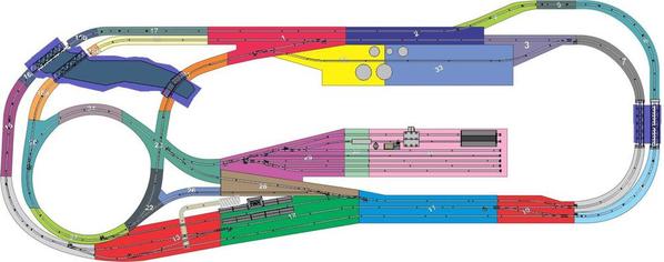
The new basement is 50% larger than the old, better situated, with no columns, unlike the old one which had the layout in the middle of the room with two columns interfering. Here's the new design done with RR Track software (highly recommended).


1408 New 5 Rev.


I attempted to use as much track from the old layout as possible which accounts for the similar design. My operating philosophy is long trains that go around and around. I don't get excited by scale operating sessions, but love to watch trains go by (real ones too). The original design was all one level which was necessitated by it being originally built in a house in Germany where I worked from '99 to '02. It was then moved back to Philly and 6' added. In this case another 11' are being added to length and 2' to width. I am restricted in the new space width-wise which really constrains large-radius designs. I'm using 0-96 for the large curves and that's 8 ft just to make a simple circle.


I've expanded all track center-to-center distances by at least a half inch. I eliminated the yard-track crossing, and made a large open center with a duckunder (ugh) to get to the lard tracks. And to make things a bit more interesting, the outer track is raised for the back half of the layout coming back on level in the front where the RR station is. One smaller note I brought all #cross-over switches to the front so they're easily accessible. These switches can be areas of trouble and I wanted them near the operations center. The back of the layout is against a wall which means that I can actually do some backdrop work which I couldn't do in the old house.


I will have to add track, a few more switches, and 11 sheets of plywood and all new Flexibed. I'm estimating that the new rendition will cost about $2,000+. This doesn't include tons of plaster cloth and roadbed gravel.


The rebuild also gives the opportunity to use Star Wiring instead of ground-loop which configures it properly for MTH DCS (plus a Lionel TMCC add-on) so I can take advantage of the latest engines that I have with PS 2.0 and TMCC. My previous wiring did not have equal length out and back leads and I didn't relish rewiring it. Now that I'm basically starting over... no big deal.


I've designed all the subroadbed ply on Corel Draw. It exactly matches the track profile that was imported in-scale to Corel Draw. The question became how to cut the ply so it conforms to the design. My nephew, the artist, suggested projecting the images of each piece, full-size, onto the ply directly from the computer. I just so happen have an In-Focus projector, that after a $300 repair bill will work. Once I buy and have the ply delivered, I will project the piece images in the garage, use a Sharpie to outline each piece and cut them in the garage. I have a sharp bend in the cellar stairs and don't think I can handle a 4 X 8 sheet into the basement. I will cut them and then carry the sub-roadbed pieces downstairs. I did the same thing in Germany, cutting the pieces out in the foyer and then carrying to the basement myself. My wife was back in the States visiting at the time AND the foyer was large with a tile floor, in case anyone is wondering how I pulled that off.


I just tried uploading another picture but the system seems to be in trouble. I'll load it in a separate entry. Since I've cut no lumber, if there's  any corrections or ideas I will easily be able to incorporate them, so have at it.


Attachments

Images (2)
  • L1 final
  • 1408 New 5 Rev.
Last edited by Trainman2001
Original Post

Replies sorted oldest to newest

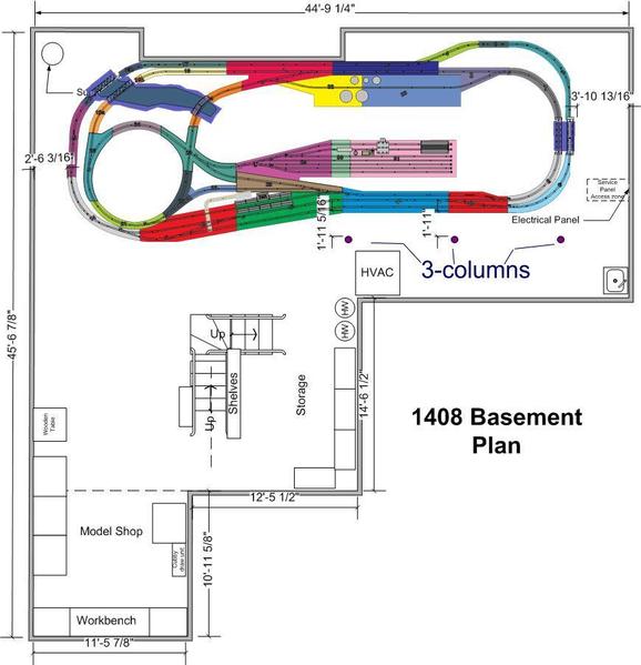
Here's the subroadbed design as drawn in CorelDraw. And here's how it looks in the space. I drew the room design in MS Visio. This is really helpful in understanding what works and what doesn't.


1408 Construction letter sized


Here's the room:


1408 layout 1 rev


I'm planning a mountain in the back right corner and some more aggressive landscaping on the left-hand edge where the outer loop is at a higher level than the inner. I didn't want the elevated level to block the view of the inside so I've limited it to the back where it's elevation will make it easier to see.

Attachments

Images (2)
  • 1408 Construction letter sized
  • 1408 layout 1 rev
Last edited by Trainman2001

I think the new design is far superior to the old one. It has distilled what you were looking for into a very practical and logical scheme. I also enjoy watching trains go by and this layout makes for some operating variety without "going crazy". Is the yard at the same elevation as the mainline or does the yard lead go over or under that crossing?

It looks great, are the white areas walking space?


How will you turn your engines, the loop on the left side area (of the yard) can be used, but can you place a Wye closer to the yard or maybe a turntable?


I recently saw Keystoned Ed's PRR 2-rail layout nearby in Williamsburg and large layouts like his and yours are simply fantastic.  His rendition of Horseshoe Curve had more track in it than my entire layout


Hope to see more progress photos soon!

There are double reverse curves in the design which lets trains turn in either direction. Also a train can be brought from the yard to any section of the layout. I have really big, really heavy motive power and don't like lifting them to put them on the tracks, ever. Just like the real ones. I will take my time. My main goal is to get the trains running again. I don't like all of them sitting in their boxes with their batteries (leaking). At least NiMH batteries don't leak like the old carbon zinc batteries in Lionel 1950s Santa Fe's....(experience).

Hello trainman2001, i will have escrow close on our need house this friday, do not know were the trains will run, my wife let me know today she whats booth of girls trains will run on the new layout, one is the 1957 girls set and the other is girls k-line set, plus all the trains i all ready have, when  think i have handeld, more suff on the new layout, Richard Yegan

Originally Posted by Trainman2001:

Here's the subroadbed design as drawn in CorelDraw. And here's how it looks in the space. I drew the room design in MS Visio. This is really helpful in understanding what works and what doesn't.


1408 Construction letter sized


Here's the room:


1408 layout 1 rev


Perhaps someone can shed some light on why these didn't load in the last post...


I'm planning a mountain in the back right corner and some more aggressive landscaping on the left-hand edge where the outer loop is at a higher level than the inner. I didn't want the elevated level to block the view of the inside so I've limited it to the back where it's elevation will make it easier to see.

DSC00842

DSC00844

DSC00845

DSC00846

DSC02635

DSC02636

Attachments

Images (6)
  • DSC00842
  • DSC00844
  • DSC00845
  • DSC00846
  • DSC02635
  • DSC02636

Your welcome ! If you need more pictures or other information just contact me and I will be glad to help. Don't forget curved turnouts by Ross, they make your straights longer. You could probably make them fit in the lower right corner where duck under is. I have a curved turn out on this swinging access and all curves are super elevated. 

Last edited by clem k

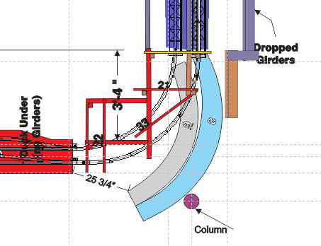
Here's a quick drawing showing the swing out in that corner. The lower left corner has too much going on although it is more accessible. There is a Lally Column near the right corner and I'm showing it in this sketch. The opening would be a maximum of 25" not taking any framing into consideration.


Swing out Proposal


I didn't change any of the L-girders. That can wait until you review the actually opening and let me know if it's feasible.

Attachments

Images (1)
  • Swing out Proposal

I don't know how to separate the photo's or write under them, I don't have a power off on the swing out I should do that, I had a dead line to meet and just never did it. I have a curved turnout on this gate.  Angle the casters to match your arc.  2x4 on each end of the joining tables set the height they actually lift the table slightly and 1x4 attached to the gate inside edge hinge end line up the table horizontal another 1x4 attached to the table inside edge on the closing end, keeps gate from closing to far.

I didn't see any latching system. How to you hold it closed? Do you have any tracking problems with all those switches leading to the swing-out?


When you insert the pictures, you can insert them inline with the text. It's a check-box in the download box. You can then annotate each picture as you develop your post.


Do you have an overall track plan? Also, that looks like a vinylbed roadbed product... what is it?

Add Reply

Post
The Track Planning and Layout Design Forum is sponsored by

AN OGR FORUM CHARTER SPONSOR

OGR Publishing, Inc., 1310 Eastside Centre Ct, Suite 6, Mountain Home, AR 72653
800-980-OGRR (6477)
www.ogaugerr.com

×
×
×
×
Link copied to your clipboard.
×
×