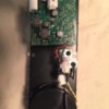
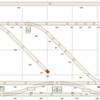
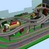
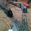
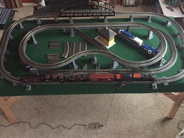
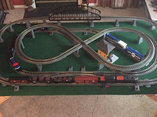
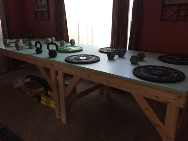
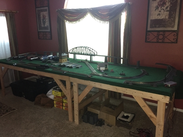
Hi all I am brand new to the hobby and have spent that last few weeks reading the forum and watching as many videos as possible to try and get up to speed. I am on my third revision of my layout which I borrowed from another member on here (see picture) I just had to move my switch down from the 0-31 curve because my locomotive was derailing occasionally.  I have one 4x8 bench and besides that nothing is permanent yet. I have been doing a lot of troubleshooting on my own but don’t want to damage my locomotive. 

I have the MTH RTR PRR Set and I am using 0-31 real trax and I added the MTH 30 inch bridge and 24 piece trestle set. In the video you can hear the squealing noise of the locomotive as it goes down the grade.  The speed is at 9 mph on the app and the faster I go the less noise there is. I turned off all sounds so what you hear is what is coming from the locomotive my other rolling stock do not make any noise. Not sure if this is a braking feature as the locomotive tries to slow down or if it is resistance going down the grade that may be damaging the motor. Any tips would be appreciated thanks. 

Attachments

Images (1)
  • F176752B-D9C5-40CC-B7CF-0CA9A943244B
Videos (1)
B0478C5A-809D-475E-B0FC-E638BC113A21
Original Post

Replies sorted oldest to newest

A product number will help those with expertise diagnose.  But, you might try this if you haven’t already.  Disconnect the tender from the locomotive and run separately.  From video, it seemed to me to get louder as the tender rolled by.  Regardless, small drops of light oil on the axels of all wheels(loco and tender) are indicated.  If the squeak is isolated to the locomotive you will remove the shell and apply small amount of grease to the drive.  Hope this helps.

TedW posted:

A product number will help those with expertise diagnose.  But, you might try this if you haven’t already.  Disconnect the tender from the locomotive and run separately.  From video, it seemed to me to get louder as the tender rolled by.  Regardless, small drops of light oil on the axels of all wheels(loco and tender) are indicated.  If the squeak is isolated to the locomotive you will remove the shell and apply small amount of grease to the drive.  Hope this helps.

Thanks for the tips and I will try them this evening.

Here are the product numbers:

MTH30-4244-1 PRR 2-8-0 Steam Freight Set PS 3.0

MTH40-1111 O 2- Track Steel Arch Bridge - Black

MTH40-1113 RealTrax - Graduated Trestle


I wasn't sure about my trestle spacing but have them about 5 inches apart,

   Tressel placement is ideally directly under the track joints or as close as possible anyhow.  Other than that, weight and deflection dictates what is "correct".

  My locos vary from about a pound to about 7lbs and I don't have huge locos. Obviously the latter needs more support.


   The sound shouldn't be ignored, nor hunting the source delayed. It sounds like a lathe cutting metal (may or may not be that serious)   Start hunting for metal on metal scratches on and around the wheels.

  Check gears for grease asap. This would not be a good sound comming from gears. (make sure grease is ON the gears and didn't miss at the factory)  Address issues one at a time slowly. It should also reveal where to keep inspecting for at least a while, and then long term.

  E.g., oil only one axle at a time. If you oil them all then test, you don't know where the issue was once it stops.  "Process those eliminations; slowly"

  If it is 2r/3r convertible, look at wheel wipers or contact plungers. Also, Ive had some similar squeek emitted by brand new shiney, hard wheel treads & flanges. That faded; plus they were plastic trucks, so I knew what it was once I had narrowed to the tender.

For oil where too slick of oil isn't wanted, try Wahl hair clipper oil. Very thin, does lube and protect, easily wiped off or cleaned 100% with solvent (alcohol, naptha, etc).  It doesn't make a slippery mess especially if applied by wiping. Wiping dry after won't remove it ALL either.  Enough is behind to do some good.

  Do you have alligator clip jumper wires? Jump the thing and see if the noise stops without weight or rail contact. (always carefully, some locos shouldn't be run upside-down or on thier sides [just a few though])  A chain of a few jumpers and maybe it can be run on a table or floor a foot or so to check weight sans-rails.

If you don't have a muti-meter and some jumper wires with gator-clips, start shopping. Harbor Freight often mails out a flyer-coupon for a free meter that will do fine for most of our stuff.   Jumper/test leads just make things easy peasy some days. (both are pretty common. Even our dollar store has jumpers and little analog meters sometimes...even those meters beats nothing)

(find a tool suggestion thread soon too )

We have an engine that sounds like that (Not an MTH tho, Lionel, circa 2000). Figured out that it was an electrical wiper on one of the axles. It was leaning slightly to one side, and managed to wear a slight groove into the axle. (No idea what they made that thing out of, that it can groove a steel axle!) Going around turns, the sideways thrust on the wheels causes the groove to ride against the side of the wiper, and the things starts 'singing'. Twisting the wiper, so that edge does not dig in, plus a tiny bit of grease, helped it. Something to look for.

Thanks for all the replies and information. I was able to do some troubleshooting but no fix as of yet. I disconnected the tender and it is not the source of the sound as it runs smoothly with no noise. I learned that my locomotive will no operate without the tender attached using DCS so all other tests were done with the tender. There is no noise while running on the rest of my layout that is not elevated. The noise occurs in forward and reverse as well as on both sides of the elevated sections. I saw no visible signs of wear or metal on metal scuffing. I lubricated all areas per the MTH maintenance video but one at a time retesting after each drop for resolution but no go. 

Next step would be to open her up and apply grease but the MTH tube does not come in the RTR set. Any recommendations for something I can grab from Lowe’s if not will order off of amazon as my LHS is a 2 1/2 round trip. 

Thanks in advance. 

That "squeal" in your video sounds a lot like dry steel-on-steel to me.  Look for any steel-on-steel joints, like maybe the front guide axle on the loco, or maybe something on the tender trucks, such as NICKAIX suggests or other.  I'm guessing it most likely involves an axle somewhere.  Try a tiny drop of oil on any steel-on-steel joint you find, and see if that cures the squeal.  If not, have to start scrutinizing closer until you find it and cure it with a drop of oil or grease.

Trestles - I would space the trestles further apart at each joint in the rails. This will better support the rails and decrease the grade.

Squeal - Did you use the manual volume control under the tender to turn off all the sounds?

I have watched the video several times. The squeal appears louder at the back of the locomotive than the front. You state the locomotive does not squeal on flat track, and at higher speeds, the squealing stops. I would look at the gears first and make sure they are properly greased. If you go to a hardware store for grease, make sure it is plastic compatible. I would also look at where the drawbar arm is attached to the locomotive, rear pickup roller, side rods and valve gear.


Last edited by ChessieFan72
ChessieFan72 posted:

Trestles - I would space the trestles further apart at each joint in the rails. This will better support the rails and decrease the grade.

20190320_163105

Squeal - Did you use the manual volume control under the tender to turn off all the sounds?

I have watched the video several times. The squeal appears louder at the back of the locomotive than the front. You state the locomotive does not squeal on flat track, and at higher speeds, the squealing stops. I would look at the gears first and make sure they are properly greased. If you go to a hardware store for grease, make sure it is plastic compatible. I would also look at where the drawbar arm is attached to the locomotive, rear pickup roller, side rods and valve gear.


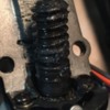
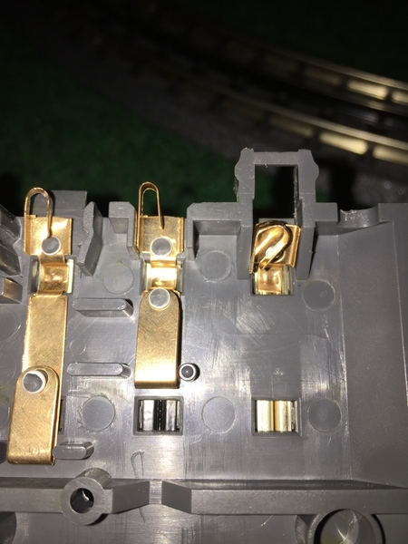
I tried to pinpoint the sound and it is coming close to the middle of the 8 wheel truck. I ordered some Labelle 106 that should be here Friday but I opened her up and there seems to be plenty of grease (see pic). I turned the sound off with the app but the speaker is in the tender and the sound definitely isn’t coming from there but I can turn the sound off under the tender.

I spaced the trestles on the side in the video all the way back to my crossover and it decreased the sound while the locomotive is in reverse but no change when in forward. The squel continues in reverse on the side where I did not adjust the trestles. All of the areas you mentioned have been oiled. 

ETA:  I also removed the bridge since it is one notch higher then the tallest pair of trestles, no change. 

Attachments

Images (1)
  • F157B572-CCB8-47DB-93C2-ED6D385D01CF
Last edited by BeachHouse

That looks like grease to me!

  Hhmm. I think I might try it on an oily track; downhill of course; to eliminate flañge squeal as a cause. If that stops it, it might quit on it's own after running a while.

Also, oil it on its side and give oil a chance to really penetrate the axle/bushing gap fully by letting it sit hours, then flip and repeat. Gramps left fresh rebuilds sit like that incase tolerances were tighter than expected once assembled.

The fact it only does it on a grade makes me want to say unplug the speaker and make 110% sure it isn't board sounds playing.

I was not thinking of the sound board but the speaker.  Tonight time permitting I will disconnect the sound board first to rule that out.  I hope that is the cause then I do not have to be concerned with any damage to the motor or moving parts. 

I will try oil on the track next if not resolved,  I will do the inner rail first then the outer.  Is it OK to do the center rail because of possible conductivity issues?  I have been using XL Gear for lubricating the locomotive should I use this on the rails or 3 in1?

Then if still not resolved I will oil one side of the locomotive and let sit overnight and flip in the AM and do the other side and let it sit all day.  

I'd try whatever is easiest to clean. Gear oil tends to be difficult to remove imo. This is only a test, if it is wheel/flange squeel you are done... it is what it is, and will need hours of running to fade. After tests, you don't want anymore than a trace of very thin oil for protection, if at all.

And fyi, checking grease on a new loco should be the first thing you do. That wasn't a waste of effort. About the time the warranty runs out, the gear would begin to fail.  Mistakes at factories happen.

3in1 will varnish long term, change to a more modern oil for your trains..  A cheap motor oil for testing would be fine. For trains Mobil One is pretty good, plastic safe etc. & there are companies  with train specific lube as well. Lots of threads on them.  A 5w-? should be fine in general.

Oil will actually slightly degrade contact for electrical, but is a "necessary evil".

You run no risk of shorting center to ground via oil (might get fractions of volts, nothing.... static has more umph.)

Just keep things tidy so your only cleaning a little track vs all, aren't slopping up the layout, etc.. (after cleaning with alcohol or other light solvent, wait to run so sparks don't ignite things)

Foam, tape, rubber bands etc. may be able to dampen any singing parts. (worry about a fix once sound is found)

Adriatic posted:

I'd try whatever is easiest to clean. Gear oil tends to be difficult to remove imo. This is only a test, if it is wheel/flange squeel you are done... it is what it is, and will need hours of running to fade. After tests, you don't want anymore than a trace of very thin oil for protection, if at all.

And fyi, checking grease on a new loco should be the first thing you do. That wasn't a waste of effort. About the time the warranty runs out, the gear would begin to fail.  Mistakes at factories happen.

3in1 will varnish long term, change to a more modern oil for your trains..  A cheap motor oil for testing would be fine. For trains Mobil One is pretty good, plastic safe etc. & there are companies  with train specific lube as well. Lots of threads on them.  A 5w-? should be fine in general.

Oil will actually slightly degrade contact for electrical, but is a "necessary evil".

You run no risk of shorting center to ground via oil (might get fractions of volts, nothing.... static has more umph.)

Just keep things tidy so your only cleaning a little track vs all, aren't slopping up the layout, etc.. (after cleaning with alcohol or other light solvent, wait to run so sparks don't ignite things)

Foam, tape, rubber bands etc. may be able to dampen any singing parts. (worry about a fix once sound is found)

Thanks for all the pointers and definitely not a waste of time or effort as I am learning a lot by troubleshooting. I tried turning of the smoke and sound turning the screws fully counter clockwise since I have been using the app and neither worked. I opened up the tender and reset the screws and then they did work no sound or smoke. I disconnected the speaker and no change in the squel. 

I oiled the rails of the section where the squel is the worse, outer then inner then Center, running the locomotive several times over the oiled sections of track and no change. Cleaned the track with Goo Gone followed by 91% isopropyl no change. 

I will try lubricating overnight and tomorrow if still no resolution I can take it back to where I bought it on Saturday and have them take a look at it. They are a forum sponsor but not an authorized service center. 

Attachments

Images (1)
  • 9129875E-F89C-4203-951D-A1B7D3B305A6

it sure sounds like the break squeal effect - when the engine slows for any reason - the break squeal can activate. I don't know if this is still a feature in PS 3.

But, with no tender and still a squeal, it rules that out.

also, I noticed no smoke - have you added smoke fluid? A smoke fan unit motor could make squeals 

if it is a drive axle, then something is definitely very dry to squeal like it is binding.

Have you sent an email to MTH about the issue? It may be known if it is mechanical.

Moonman posted:

it sure sounds like the break squeal effect - when the engine slows for any reason - the break squeal can activate. I don't know if this is still a feature in PS 3.

But, with no tender and still a squeal, it rules that out.

also, I noticed no smoke - have you added smoke fluid? A smoke fan unit motor could make squeals 

if it is a drive axle, then something is definitely very dry to squeal like it is binding.

Have you sent an email to MTH about the issue? It may be known if it is mechanical.

Yes, the brake squeal effect is still a feature in PS 3 but that is more pleasing to the ear then this. 

Yes I added smoke fluid and that feature as well as the fan work as designed. 

I spoke to the store where I purchased it just now and they said bring it back and they will handle it. 

BeachHouse posted:
Moonman posted:

it sure sounds like the break squeal effect - when the engine slows for any reason - the break squeal can activate. I don't know if this is still a feature in PS 3.

But, with no tender and still a squeal, it rules that out.

also, I noticed no smoke - have you added smoke fluid? A smoke fan unit motor could make squeals 

if it is a drive axle, then something is definitely very dry to squeal like it is binding.

Have you sent an email to MTH about the issue? It may be known if it is mechanical.

Yes, the brake squeal effect is still a feature in PS 3 but that is more pleasing to the ear then this. 

Yes I added smoke fluid and that feature as well as the fan work as designed. 

I spoke to the store where I purchased it just now and they said bring it back and they will handle it. 

I overlooked that step. Good idea. That is a better level of customer service - you may want to stick with that store. Good hear the rest is working well with it.

Hopefully the last update before this issue is resolved. I took it back to the store where I purchased it from and they do not have a graded track to reproduce the issue so the owner said he will take it to MTH on Monday and I should have it back by Friday. 

I got a great deal on a “Like New” set while there so please see the new video so you know I am not some crazed guy just imagining things. Thanks to all that helped I learned a lot and I am excited to start playing. 

Attachments

Videos (1)
A34BF11B-E4DF-42ED-A268-6AAE49A80BC3
ChessieFan72 posted:

I am confident none of us here thought you were a crazed guy. That squeal was very noticeable. I see you moved the trestles. I am sure your locomotives appreciate that, as the grades should be lower. Glad to hear you picked up another train set. Sounds like you got the bug!

I think the squeal may have been a symptom of something bigger wrong with the motor. Now that I am running the MTH RK Deisel I realize that the PRR loco was very jerky at low speeds and had a lot of slow down in the curves and that is not the case with the deisel. 

I just changed my layout to an over under. I removed the pillars from the bridge as they were a space hog, did not match the color of the trestles and also that decreases the grade. I need to figure out how to get the electronic board out of the bridge pillar for the light function as I do not see a screw that is accessible. 

I plan on adding two of the 10 inch bridges to the sides of the 30 inch bridge as I think it looks a lot better in pictures I have seen. Also another switch with with a yard line. 

I was also thinking of adding a separate loop figure 8 elevated above with no grade that would run off a second DCS Explorer since I have two now. 

Once I get things more permanent, nothing is glued or screwed yet, I am going to move the layout to where it will be placed (reach will be an issue) and I plan on adding a 4x6 table with a reversing loop all on one level no grade. 

Attachments

Images (1)
  • 5CBB7BB9-08BD-491E-91F3-442DCD3C4E21
Last edited by BeachHouse

I picked up my locomotive this weekend and some more switches to work on my layout. They said there was an issue with the gears when under stress and the squeal could be reproduced by pushing the locomotive, but it is resolved. 

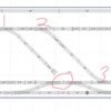
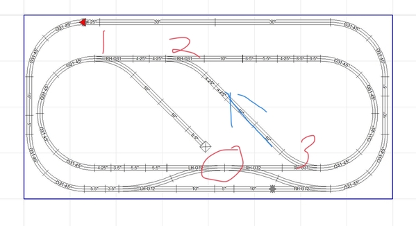
I removed the bridge and trestles for now and added some 0-72 switches and a reversing loop (see pictures).  I used the MTH RR software and soon found out that although it fits on paper it doesn't always fit or work in reality. I had to flip the switch controllers as two of them would not fit between the loops but now they overhang my bench.  

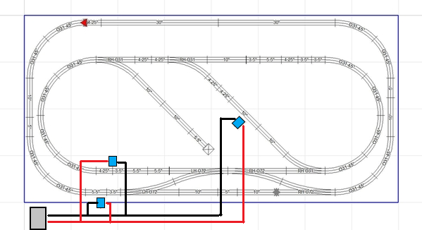
I am having two issue I need assistance with.  The first and most important is getting power and the DCS signal to the inner loop.  I am using the MTH DCS Explorer with the iphone app.  I have the explore connected to the outer loop and had no power to the inner loop.  I connected another power block to the inner loop and the trains run but I have no DCS signal and no control.  Power input is circled in red. 

Second, I have a short on my reversing loop so I need to add two 5.5" insulated track sections.  I want to make sure if I only need two and confirm where to place them, I am thinking next to the turnout on the inside track run marked in purple.

I plan on adding the bridge with only a minor elevation since nothing will be running under it for now.  

Attachments

Images (2)
  • layout
  • layout2

1 is the inner loop connected to the same output from the explorer as the outer loop? It should be. The output from the explorer needs to go everywhere you want to use DCS.

2. If you have a short in the reversing section, then you have a bad piece of track. One of the features of 3 rail is that you never have the "reversing loop short" problem that 2 rail power systems have.

Greg Nagy posted:

1 is the inner loop connected to the same output from the explorer as the outer loop? It should be. The output from the explorer needs to go everywhere you want to use DCS.

2. If you have a short in the reversing section, then you have a bad piece of track. One of the features of 3 rail is that you never have the "reversing loop short" problem that 2 rail power systems have.

1. Yes, that is how I originally had it setup, with the DCS explorer plugged into the out outer loop only but I had no power to the inner loop at all.  I removed all the trains and then tried adding just one locomotive but nothing.  Or are you saying that I need to add a spliter after the explorer output and wire that separately to the inner and outer loops?  I was thinking that I would only need one power input for this layout.

2.  Once I resolve the power issue I will work on this more.  By "short" I meant that one switch keeps on being thrown in the non desired direction and the train stops on the track.  

You should only need one power/DCS input for this layout, although additional drops may be necessary if you experience power or signal loss around the track.

I would start by removing all trains from the tracks and sidings; turn power on and measure voltage on both loops with a DVM. I am not familiar with Real Trax switches, but it "looks" like the two loops are electrically connected. If there is no voltage getting to the inner loop then there is some sort of electrical disconnect between the outer and inner loops.

I would look at the track pieces between the crossover switches to see if any of them have small cuts in the rails. It may be that they have a small wire underneath that needs to be connected like the 1 3/8 inch Fastrack pieces.

I can't expand thumbnails. They must appear here full sized to be seen. Viewer doesn't work well on most Androids.

There is a small line of type "insert into post large sized" & a checkbox that appears mid-height in the att.tool's text after loading/processing/sucesss. Check that off please.

If you forget to and hit finish, you have another way.  At the bottom in each pictures box at the post bottom, at the bottom of each photo section, blue text, "insert into post text" (or similar words). Inserting this way gives a choice of large med or small photo.

I'll post again a bit later.. nice to hear you at least gave the engine your best and it has a happy ending.

Fastening track takes away the ability to change fast on impulse. Run these for a bit and see if the interest lasts before you put the screws to it. I love the dimensional factor any el or grade brings to the party. (my party shown)

Switch machines can be a pita in software. I think SCARM does a good job with them. It's pretty accurate overall from what I saw in my uses. (in has to be for N scale track systems also covered)

scarm9x4.5~2

On wheels, and against a half-wall/divider it can be seen from both sides if backdrop is off. I ended up liking this backside view better, plus railing trans is easier on this side.

”I'll be back"😎

Attachments

Images (1)
  • scarm9x4.5~2
BeachHouse posted:


Second, I have a short on my reversing loop so I need to add two 5.5" insulated track sections.  I want to make sure if I only need two and confirm where to place them, I am thinking next to the turnout on the inside track run marked in purple.

Hi BeachHouse,

I too have a simple MTH RealTrax layout very similar to yours (albeit bigger), and have an idea on your problem...........................

Take one of your O31 switches and turn it over and look at the underside.  At the points end of the turnout, you will see 3 copper contacts, used to make positive electrical contact with the next track section that plugs into this end.  One contact on the center rail, and one contact on each of the outer rails.

Now look at the other end at both the straight route and diverging route.  You will notice only 2 copper contacts on each route.  Each center rail has one, and each outer rail has one.  The inner rails do not have a copper contact.  These are your non-derail rails.  They are not meant to make continuous electrical contact with the rest of the track.  They are only activated when a wheelset rolls over them.

When other track sections are plugged into the switches, you must also make sure the rail ENDS are not touching the diverging rails.  This will short out the non-derailing feature of the switches.  Unfortunately, I don't think quality control is the best on MTH RealTrax, and some rails tend to be just a tad too long here and there on all of their track and switch sections.

Next thing to watch out for: make sure any train you run through the reversing section is SHORTER than the length of the straight track between the switches.  If your train is longer (long enough to be on both switches at the same time), then the wheels can touch BOTH non-derail rails (can also be electrically touching without actually physically touching them, believe it or not, thanks to the rest of the oval).  This will also cause shorting out.

To sum it up........... make sure the non-derailing rails on ALL switches are electrically isolated from adjoining track pieces.  Make sure any train you run on the reversing section is NO LONGER than the straight sections of track between the switches.

Once you have achieved this, your DCS problem may also go away (or at least be much easier to trouble-shoot).

Give it a try and see if this doesn't cure your problems. 

DD828883-A866-4200-863F-65001EC812C2Thanks for all of the replies and pointers. 

I removed all trains from the track. I do not have a voltmeter (added that to my ever growing list of things to pickup) so I used my lighted caboose. I found one bad 031 curve on the inner loop and hoped replacing it would be the fix but that would be to easy. This is all new track and switches the bad piece did not have the black coating on the Center rail applied properly so I swapped it out. 

While testing the track I noticed that the caboose acted like a bridge to carry current from the outer loop to the inner loop when positioned on a switch and making contact with both, see pic hopefully now large embedded. So with this I was able to run a locomotive on the inner loop with power and DCS. 

The 031 switch at the top of the reversing loop was making contact with the diverging rail and pulling them slightly apart resolved the “short” out issue on this section of track. @Mixed Freight thanks for this as I have been making sure all of the track is fit as close as possible. 

So I inspected all of the undersides of the switches and none had an extra copper contact and the spacing and function seems to be correct as far as I can test by just pushing a caboose over them. 

So two things resolved but still no power/DCS to the inner loop. 

ETA: I just hooked up the other power block to the inner loop to test the switches with a locomotive and all of the switches are working properly when fully powered. I ran just the MTH Vetrans diesel and it is pretty neat even with the temporary workaround. 

Attachments

Images (1)
  • DD828883-A866-4200-863F-65001EC812C2
Last edited by BeachHouse
BeachHouse posted:

DD828883-A866-4200-863F-65001EC812C2Thanks for all of the replies and pointers. 

I removed all trains from the track. I do not have a voltmeter (added that to my ever growing list of things to pickup) so I used my lighted caboose. I found one bad 031 curve on the inner loop and hoped replacing it would be the fix but that would be to easy. This is all new track and switches the bad piece did not have the black coating on the Center rail applied properly so I swapped it out. 

While testing the track I noticed that the caboose acted like a bridge to carry current from the outer loop to the inner loop when positioned on a switch and making contact with both, see pic hopefully now large embedded. So with this I was able to run a locomotive on the inner loop with power and DCS. 

The 031 switch at the top of the reversing loop was making contact with the diverging rail and pulling them slightly apart resolved the “short” out issue on this section of track. @Mixed Freight thanks for this as I have been making sure all of the track is fit as close as possible. 

So I inspected all of the undersides of the switches and none had an extra copper contact and the spacing and function seems to be correct as far as I can test by just pushing a caboose over them. 

So two things resolved but still no power/DCS to the inner loop. 

So... you may not realize it, but the two problems *are* related. 

Your inner and outer loops are connected by two crossovers. Think about that missing piece of copper on the switch. For each connected crossover, there is a break on EACH outer rail. The caboose, bridging the gaps, completes the circuit. 

As I suggested before, you need power run to each loop individually. If you look at the DCS TIUs, they have multiple outputs. MTH also sells an item that looks  like a breakout board full of banana plug jacks. While not the "reccomended" (star wiring) way, you are small enough that you can probably get away with the following. Run the wires from the explorer to the outer loop. Now.. each of those plugs are both a banana plug, and a wire nut. You can attach wires, using the wire nuts, that run from the outer track connector, to the inner track connector. Be sure to connect red to red and black to black. 


@ADRIATIC  No, Sorry. I am from the Pittsburgh area. The surname "Nagy" and its derivative spellings is a popular Hungarian name so lots and lots of us out there. It actually translates into 'Large/great' 

Greg Nagy posted:
BeachHouse posted:

DD828883-A866-4200-863F-65001EC812C2Thanks for all of the replies and pointers. 

I removed all trains from the track. I do not have a voltmeter (added that to my ever growing list of things to pickup) so I used my lighted caboose. I found one bad 031 curve on the inner loop and hoped replacing it would be the fix but that would be to easy. This is all new track and switches the bad piece did not have the black coating on the Center rail applied properly so I swapped it out. 

While testing the track I noticed that the caboose acted like a bridge to carry current from the outer loop to the inner loop when positioned on a switch and making contact with both, see pic hopefully now large embedded. So with this I was able to run a locomotive on the inner loop with power and DCS. 

The 031 switch at the top of the reversing loop was making contact with the diverging rail and pulling them slightly apart resolved the “short” out issue on this section of track. @Mixed Freight thanks for this as I have been making sure all of the track is fit as close as possible. 

So I inspected all of the undersides of the switches and none had an extra copper contact and the spacing and function seems to be correct as far as I can test by just pushing a caboose over them. 

So two things resolved but still no power/DCS to the inner loop. 

So... you may not realize it, but the two problems *are* related. 

Your inner and outer loops are connected by two crossovers. Think about that missing piece of copper on the switch. For each connected crossover, there is a break on EACH outer rail. The caboose, bridging the gaps, completes the circuit. 

As I suggested before, you need power run to each loop individually. If you look at the DCS TIUs, they have multiple outputs. MTH also sells an item that looks  like a breakout board full of banana plug jacks. While not the "reccomended" (star wiring) way, you are small enough that you can probably get away with the following. Run the wires from the explorer to the outer loop. Now.. each of those plugs are both a banana plug, and a wire nut. You can attach wires, using the wire nuts, that run from the outer track connector, to the inner track connector. Be sure to connect red to red and black to black. 


@ADRIATIC  No, Sorry. I am from the Pittsburgh area. The surname "Nagy" and its derivative spellings is a popular Hungarian name so lots and lots of us out there. It actually translates into 'Large/great' 

I understand what you are saying now, I need to have power to both loops, since the inner loop is isolated by the double crossover,  coming off of the Explorer. I will wire that up tomorrow after work if that doesn’t work then I guess I will be getting a TIU. 

BeachHouse posted:

I picked up my locomotive this weekend and some more switches to work on my layout. They said there was an issue with the gears when under stress and the squeal could be reproduced by pushing the locomotive, but it is resolved. 

I removed the bridge and trestles for now and added some 0-72 switches and a reversing loop (see pictures).  I used the MTH RR software and soon found out that although it fits on paper it doesn't always fit or work in reality. I had to flip the switch controllers as two of them would not fit between the loops but now they overhang my bench.  

I am having two issue I need assistance with.  The first and most important is getting power and the DCS signal to the inner loop.  I am using the MTH DCS Explorer with the iphone app.  I have the explore connected to the outer loop and had no power to the inner loop.  I connected another power block to the inner loop and the trains run but I have no DCS signal and no control.  Power input is circled in red. 

You have lost the common where the switches cross-over due the way that MTH wires them for non-derail. Now, you need to run a pair of wires from the DCS Explorer to the second lock-on.

Second, I have a short on my reversing loop so I need to add two 5.5" insulated track sections.  I want to make sure if I only need two and confirm where to place them, I am thinking next to the turnout on the inside track run marked in purple.

A short is not good. Is it kicking the breaker on the power supply? Describe what you mean by "a short" ? 

I plan on adding the bridge with only a minor elevation since nothing will be running under it for now.  


here's your layout-fit  the roadbed will be touching at the ends on the inner loop

Beachouse

Which track do you want to isolate with the 2 - 5" #40-1029 ?

Check the controller wires to the switch that is the problem child - don't screw it down tight-only the adjoining tracks and only snug to hold track- remove it and reinstall it - close the loop away from the offending switch and get easy track connection with the adjoining tracks first.

Attachments

Images (1)
  • Beachouse
Moonman posted:  You have lost the common where the switches cross-over due the way that MTH wires them for non-derail. Now, you need to run a pair of wires from the DCS Explorer to the second lock-on. 
 
A short is not good. Is it kicking the breaker on the power supply? Describe what you mean by "a short" ?

Thanks for the reply. A previous poster explained that to me and I will be wiring that up this evening. 

The “short” issue was resolved it was being caused by the top switch on my reversing loop. One of the isolated rails was making contact with the adjacent tracks rail. So every time the train would go onto the adjacent rail the switch would throw and all power to the track would shut off. 

BeachHouse posted:
Moonman posted:  You have lost the common where the switches cross-over due the way that MTH wires them for non-derail. Now, you need to run a pair of wires from the DCS Explorer to the second lock-on. 
 
A short is not good. Is it kicking the breaker on the power supply? Describe what you mean by "a short" ?

Thanks for the reply. A previous poster explained that to me and I will be wiring that up this evening. 

The “short” issue was resolved it was being caused by the top switch on my reversing loop. One of the isolated rails was making contact with the adjacent tracks rail. So every time the train would go onto the adjacent rail the switch would throw and all power to the track would shut off. 

Ok, sounds good - the replies get busy and I couldn't filter what was being said - most likely a result of fit from the track plan - that would cause a short - the default fitment in RR-Track and auto fit can create build issues from the plan to build - if you check the fitment that I created there are only two small gaps

Are you ok with the DCS signal now? 

Moonman posted:
BeachHouse posted:
Moonman posted:  You have lost the common where the switches cross-over due the way that MTH wires them for non-derail. Now, you need to run a pair of wires from the DCS Explorer to the second lock-on. 
 
A short is not good. Is it kicking the breaker on the power supply? Describe what you mean by "a short" ?

Thanks for the reply. A previous poster explained that to me and I will be wiring that up this evening. 

The “short” issue was resolved it was being caused by the top switch on my reversing loop. One of the isolated rails was making contact with the adjacent tracks rail. So every time the train would go onto the adjacent rail the switch would throw and all power to the track would shut off. 

Ok, sounds good - the replies get busy and I couldn't filter what was being said - most likely a result of fit from the track plan - that would cause a short - the default fitment in RR-Track and auto fit can create build issues from the plan to build - if you check the fitment that I created there are only two small gaps

Are you ok with the DCS signal now? 

I have to run wire from the lockon on the outer loop, that is using the banana plugs from the DCS, to the lockon in the inner loop and see if I get enough power and DCS signal to run two trains simultaneously. 

Once that is working I still have to change a few things before I "finalize" my layout and screw it down.

Wired and working! I have power and DCS signal coming off the Explorer going to both loops and I am able to run two trains simultaneously. I need to see if I can lengthen the reversing loop section so that I can run the 4 car Vetrans diesel thru it as that was my intent  4DA03BE9-612C-458D-A39F-EC6663A60802

I have power loss in the circled area in the picture where the two 072 switches connect. I can hear it when a train crosses that area from either direction and the train slows down and will stop at lower speeds 3smph. 

The one 031 switch continues to be a problem. I make sure there is separation on the inner rail but the train can go over it four times and on the fifth time the derail feature will kick in and shut power down to the entire track. I tried swapping it with another 031 switch to see if it was the location but no change.

Does anyone have a good resource they could point me to on the derail feature as well as wiring and switch function in general I spent 4 hours tonight but something just doesn’t seem right. 

Attachments

Images (1)
  • 4DA03BE9-612C-458D-A39F-EC6663A60802

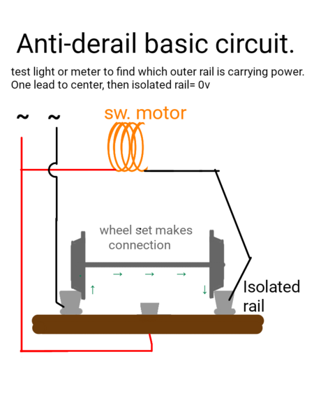
This is the basics for anti-derail.  Internals may vary some for electronic boards, and some tracks use tabs that rub the backside of wheels vs isolated rails, but the basics on the outside iso-rail and general paths are pretty much the same.

Some brands may also need diodes added for mods, etc. due to boards (Z-stuff might, etc) , but I don't recall that ever mentioned or comming up for MTH. That shouldn't come into play here anyhow since you aren't adding to the system or modding it; mentioned only in case you get "creative". In that case, more research would be very prudent.

You can also take scrap wire to a non-turnout outer rail, then the other end touched to the isolated trigger rails will cause the points motor to move. If you try one exit without response on either rail, try the other exit. If that moves, retry the first side. They may contain a lock out that is dependant on position. (would keep a coil motor from trying to move if it is already in position. ItIt would also allow a thinner wire for coil winding without as much concern for overheating as it would yield more cooling/off time.  Coils are just an electromagnet and they produce heat while working.)


sketch-1554875893988

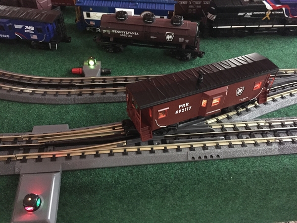
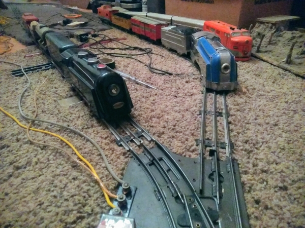
Look close at the center rail at the turnout below, in front of the blue Crusader. See the tiny square of electrical tape? It is preventing two blocks from contacting. You can trim better than that, right?   They won't stick out like a sore thumb if trimmed close and always stay put for me (remember these rails are empty tubes without a lot of surface. Even that sloppy one has been there for months now, and my haste in it's placement is pretty obvious. That thin, it still leaves a gap on the right even though the tape isn't actually covering the right side of that rail's head and footing. You only need a hair gap; it either touches or doesn't. 20v isn't going to jump a few mill.s of space like a much higher voltage might.

IMG_20181127_194216~2

Attachments

Images (2)
  • sketch-1554875893988
  • IMG_20181127_194216~2

I assume that the switches are being powered by track power. Is this correct?

You could try relocating a couple of pieces of track and separate the switches. Move the left side switch toward the left.

Like this:

Beachouse1

The other thing to check is how the controller is connected. The connection points are in reversed order between left and right. The switch manual has a page to show that. 

The other thing to check is making sure the switch motor is installed correctly. It can feel like it is properly and not be. Follow the method in the manual. 

Finally disconnect the switch controller to eliminate that as a problem. 

I have not had a switch open to know the internal wiring. Not many, if any at all, have failed internally based on forum post observation.

You may want to check the connector tabs on the ends to ensure that they are not bent of malformed from assembly/disassembly.


reverse loop:

I measure the reverse loop as 124 3/4" 

Beachouse2

The engines are 18 1/2" and the cars are 15"  so it should be 78" - 80".

It should not hit it's tail turning around.

Circle a track diagram for what you are looking to do.

The problem is that there is only one reverse loop. You cannot return to the opposite direction again. This would solve that issue:

beachouse_depressed_fig_8

OK, tee time is coming - gotta go.


Attachments

Images (3)
  • Beachouse1
  • Beachouse2
  • beachouse_depressed_fig_8
Moonman posted:

I assume that the switches are being powered by track power. Is this correct?

You could try relocating a couple of pieces of track and separate the switches. Move the left side switch toward the left.

Like this:

Beachouse1

The other thing to check is how the controller is connected. The connection points are in reversed order between left and right. The switch manual has a page to show that. 

The other thing to check is making sure the switch motor is installed correctly. It can feel like it is properly and not be. Follow the method in the manual. 

Finally disconnect the switch controller to eliminate that as a problem. 

I have not had a switch open to know the internal wiring. Not many, if any at all, have failed internally based on forum post observation.

You may want to check the connector tabs on the ends to ensure that they are not bent of malformed from assembly/disassembly.


reverse loop:

I measure the reverse loop as 124 3/4" 

Beachouse2

The engines are 18 1/2" and the cars are 15"  so it should be 78" - 80".

It should not hit it's tail turning around.

Circle a track diagram for what you are looking to do.

The problem is that there is only one reverse loop. You cannot return to the opposite direction again. This would solve that issue:

beachouse_depressed_fig_8

OK, tee time is coming - gotta go.


Yes, all switches are using track power only for now. 

I added some 3.5” pieces to separate the O72 switches and that worked no more power loss. 

Thanks for all the troubleshooting steps on the switches. I will work on them next but probably won’t get to them until the weekend. I will upload a video to show the intermittent issue I am having with the O31 switches.  It does not seem to matter what position the other switches are in at that time and all I have to do is refresh the locomotive in the app and it works  

I misunderstood the points of contact for the reversing loop. I ran the 4 cars thru in both directions and no issues. I was thinking of doing something like you have pictured since I have the crossover but would need another O31 switch. Also the MTH imperial locomotive I have although it works on O31 it overhangs the outer edge on curves and wasn’t sure if the trains would collide. 

Attachments

Videos (1)
FF4B4F25-2127-4D39-861A-A5BB5C121788
Last edited by BeachHouse

That looks like a controller wiring issue in the video 

The ends of the inner loop would be very close to a collision on the ends. I don't see a way to increase it.(move the closer to the center.)

Extending the table 4" on the left and 3" on the right for a 103" length would permit spacing the outer loop out with a 3.5" track and solve the clearance issue.

beachouse_depressed_fig_8_103_inch

Nice work. You are almost there!


Attachments

Images (1)
  • beachouse_depressed_fig_8_103_inch
Moonman posted:

Here is the current track plan extended 4" on the left and 3" on the right - this is as easy as two 2 x 4 screwed on to the end on the table frame. Drill holes through extension piece, then, attach the first and then,  the second to the frame end board.

Beachouse2_extended_table


Once I get this setup more finalized I plan on adding another 4x8 table to make a "L" shape or possibly two smaller tables to make a "U" shape.  I will be adding the 30 inch bridge back in so I will need to replace the one 30 inch track piece with three 10 inch to make the trestles work properly, but then the bridge will not be centered so may have to buy two more 5" track pieces.  I will be adding the lowest elevation trestles beginning at the outer ends of the O72 switches, so where the red begins and then working towards the center back of the outer loop.  I added a 4.25" piece to the outer middle of each end of the inner loop and switched the two turnouts to make the reversing loop a little bit longer. 

I need to make something to mount the switch controllers and the DCS Explorer unit to.  I have some black flat head 1 1/2 screws to mount the track but not sure about doing that yet.  I have the green carpet on top of a 2"  4x8 foam board that I plan on gluing to the 5/8" plywoood. 

I picked up some woodland scenic tree 4 packs from AC Moore on Saturday they were 60% off so $6 each and some fabric to make a curtain around the table.  I was looking for a backdrop but all they had was clouds and I am thinking green hills if you know of anyone that sells them.  Also I like the look of the rows of building fronts but have not seen them in person.  

I was able to run two trains in opposite directions on both loops for 20-30 minutes last night with no issues. The O72 switches work excellently and the trains function smoothly thru them.  I will try the black electrical tape and the other troubleshooting steps on the O31s this weekend.   I was trying out the different DCS functions in the app.  I don't like that you can not control both trains simultaneously as I almost had a crash.

Thanks for all the help!

Richie C. posted:

As a backdrop alternative, you might want to check out Staples. If you download a scenic picture from the internet (like Google Earth), they can blow it up and print to various backdrop sizes.

Looked into this online and for a 4 foot poster the base price is around $100 and I would need two. Hopefully I can find a less expensive option.

C4CF00B2-6B61-40E1-92A4-6F41C7437ACD01BC2F39-7E5E-4A34-8525-052105EBFE88I think but hope not that this is just an operator = me error.  I have been working on the switches all morning but still not resolved. My volt meter arrived and I have 15 volts around the entire layout. To try and simplify things I modified the layout and to just focus on the inner loop with the O31 switches. It is not an issue with an individual switch as if I swap the “good” switch out I can replicate the same issue.

So if it is my misunderstanding on how these switches work then the switch would have to be in the proper position prior to the locomotive entering. But when the power cuts out all I have to do is refresh the app and the locomotive can continue on so I do not think that is the issue as that is not how the O72 switches operate. 

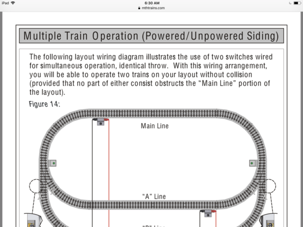
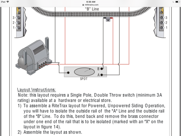
I did find this in the instruction manual (see pics) so even though I am not trying to control 2 switches with 1 controller thought this may work but didn’t want to bend out the copper connectors unless sure. 

I am going to do some yard work or I will need a drink but appreciate any further input. 

Attachments

Images (2)
  • C4CF00B2-6B61-40E1-92A4-6F41C7437ACD
  • 01BC2F39-7E5E-4A34-8525-052105EBFE88

Your instruction manual wiring diagram and instructions are so screwed up, I don't know how anyone can properly wire their layout following these instructions and drawings to the letter.  I've got the same instructions with my switches, but I didn't pay any attention to this particular section when I put my layout together.  Thank goodness for that!

First off, if you are using an SPDT switch to route power as they show, then you need to wire it up to the center rails (which they don't show in the diagram), and not to the "outer" rails.  And isolate the center rails, of course.  If you have at least one reversing section (which you do have), then an outer rail can become an "inner" rail as you travel through a reversing section, and thereby cause potential electrical problems.

As far as isolating rail sections, don't bend out the brass copper connectors if you wish to electrically isolate a connection.  Why ruin good pieces of track?  Simply put a small piece of electrical tape on one (or both) of the copper connectors to prevent them from contacting each other.  Make sure the rail ends don't touch either, as we have previously learned.

If you are powering your switches through the track, then the momentary power draw as a switch "snaps" may be causing your problem.  You may wish to try powering your switches through the accessory output of your transformer or else a separate transformer.

Just some suggestions, hopefully this helps you further along.

BF11019E-B705-4455-893B-48E85BAD813909B589FB-918F-48CB-955D-6828BF7C7CDCMixed Freight posted:

Your instruction manual wiring diagram and instructions are so screwed up, I don't know how anyone can properly wire their layout following these instructions and drawings to the letter.  I've got the same instructions with my switches, but I didn't pay any attention to this particular section when I put my layout together.  Thank goodness for that!

First off, if you are using an SPDT switch to route power as they show, then you need to wire it up to the center rails (which they don't show in the diagram), and not to the "outer" rails.  And isolate the center rails, of course.  If you have at least one reversing section (which you do have), then an outer rail can become an "inner" rail as you travel through a reversing section, and thereby cause potential electrical problems.

As far as isolating rail sections, don't bend out the brass copper connectors if you wish to electrically isolate a connection.  Why ruin good pieces of track?  Simply put a small piece of electrical tape on one (or both) of the copper connectors to prevent them from contacting each other.  Make sure the rail ends don't touch either, as we have previously learned.

If you are powering your switches through the track, then the momentary power draw as a switch "snaps" may be causing your problem.  You may wish to try powering your switches through the accessory output of your transformer or else a separate transformer.

Just some suggestions, hopefully this helps you further along.

Well one more step forward tonight as seen in picture when I was going to tape off the connectors I noticed the bent one on a straight piece and replacing that did make a difference. 

I am not running SPDT and have no other power options currently  I am not sure if I want to take the plunge on a WIU TIU AIU at this point  

Like you said It is definitely a polarity issue which I did not think I would have with three rail and these switches. When the power shuts off and I refresh the app that is temporarily resolving the polarity issue but it just returns.  It has nothing to do with the O72 VS O31 but the switches on the inner reversing loop. I tried electrical tape and spacing and have all switches working properly with the exception of switch number 2  if the train is traveling in the direction from switch 3 towards switch 2 and switch 2 is not open it engages but I loose all power like in the short video I posted  I will try some electrical tape combinations tomorrow to see if I can finally get this resolved  

Attachments

Images (2)
  • 09B589FB-918F-48CB-955D-6828BF7C7CDC
  • BF11019E-B705-4455-893B-48E85BAD8139
Last edited by BeachHouse

 That digram works as a choice for running either A or B siding, but only for 2rail track that I can figure. ...unless there is some command aspect I'm missing and it's not focused on in the text.

But pretend it has a third rail:

Move black colored wires to all red terminals & visa versa red wire to blk term, so the switch is on the center rail. Move the sidings X-isolation to siding center rails. Now only one siding is powered at a time off the toggle. 

Finally verify each exits anti trigger rail is also isolated.

All done for loop and sidings as shown in that diagram.

Any turnouts added after are treated as an addition.

So, building off that; if two isolated rails of any kind, be it anti-derail, reverse loop, or crossing gate trigger, happen to by pure chance also isolate a section of the mainline hot or com., you have to feed that section its power leg by a new drop. It is your choice of  how because it is essentially a new block to be addressed alone or grouped to another block.

I'm beginning to guess your mixing folks instructions together, and in conjuction with experiments of your own, a little too liberally.

 Every change sets any one process of elimination back to square one, and the cycle begins again vs progression with at least one item now off the list.

You can mix advice, but if you don't complete the advice and expand on result, plus leave us with "present state" it's hard for everyone and anyone to advise.

Stick to one path so it can "come full circle". Others helping will usually try to shift that way unless they see a danger, the point of communication breakdown, etc.... but the direction seems kinda scattered here from too much change.

Ok, I am thinking this may be a Starter set issue - as in the transformer is only intended for use with the track (small loop) that is included with the set. I am thinking that the power supply breaker is kicking when the surge from the switch throws.

I noticed this from watching the video again - switch motor light on - train running - train hits switch trigger rail - switch out of position - switch throws - switch power light goes out and train stops. The surge of current required by the switch causes an overload.

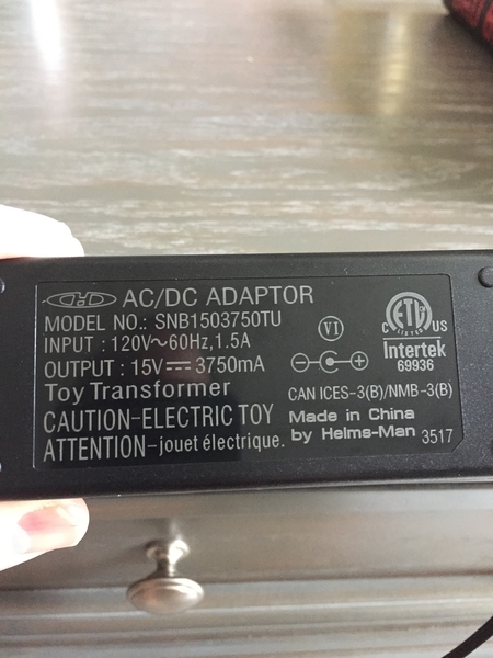
Would you look at the specifications on the power adapter and post them? I didn't find them in the set instructions or the DCS Explore instructions.

You now have an "advanced layout" that would require a transformer with a higher current supply. The Z-1000 transformer only plugged into the DCS Explorer (replacing the starter set power supply) will most likely solve the issue.  

You can bend that connector into shape with needle nose pliers.  

Track assembly tip - Hold the pieces of track in a V with the railheads touching and the fold the ends down. The track will smoothly connect. This gets more difficult as you build a loop - so, holding one piece in half of the V or lifting both to get a flattened V still connects better than a straight, flat push together move. Disconnecting is the reverse, lifting the far ends from a joint up. Again, this is a pain on the first joint to break a loop, so, any small angle will unlock the tabs easier. This helps prevent bending the connector tabs. 

Last edited by Moonman
A6174BCA-266A-4B1F-9B71-89E91A89913ETThe Moonman posted:

Ok, I am thinking this may be a Starter set issue - as in the transformer is only intended for use with the track (small loop) that is included with the set. I am thinking that the power supply breaker is kicking when the surge from the switch throws.

I noticed this from watching the video again - switch motor light on - train running - train hits switch trigger rail - switch out of position - switch throws - switch power light goes out and train stops. The surge of current required by the switch causes an overload.

Would you look at the specifications on the power adapter and post them? I didn't find them in the set instructions or the DCS Explore instructions.

You now have an "advanced layout" that would require a transformer with a higher current supply. The Z-1000 transformer only plugged into the DCS Explorer (replacing the starter set power supply) will most likely solve the issue.  

You can bend that connector into shape with needle nose pliers.  

Track assembly tip - Hold the pieces of track in a V with the railheads touching and the fold the ends down. The track will smoothly connect. This gets more difficult as you build a loop - so, holding one piece in half of the V or lifting both to get a flattened V still connects better than a straight, flat push together move. Disconnecting is the reverse, lifting the far ends from a joint up. Again, this is a pain on the first joint to break a loop, so, any small angle will unlock the tabs easier. This helps prevent bending the connector tabs. 

I figured out how to assemble the track pieces when it was just a starter set but will admit I was trying to push them together flat on the table which was near impossible and probably caused the damage that I was able to fix last night with a needle nose pliers  thanks for the V tip  

It is a 50 watt power supply (see pic) with 15 volt output which is what I was getting on my voltmeter. I did look at picking up just the Z-1000 power brick used on ebay. If it is a power supply issue howcome the other switches do not cause it? 

So just as a quick test I have made no other changes so everything else is constant. I plugged in the extra starter set power supply and connected it to the lock on in the inner loop via the banana plugs. This lock on was and still is using the wire nut connections from the outer loop lock on that I needed to get DCS signal to the inner loop.  So I now have two 50 watt power supply to the track and I did notice a difference see videos. If you look carefully in both videos when the locomotive (just using one car for testing) triggers the switch controlor it does not fully engage and power to the entire track ceases, but when using two power supplies they exact same thing happens but the  “extra power” perhaps is enough to kick in and override it? But I am not sure what technically is happening here but makes me think it is not a power issue but a polarity issue.  


Attachments

Images (1)
  • A6174BCA-266A-4B1F-9B71-89E91A89913E
Videos (2)
59A6EC0E-11B1-4F52-A6F5-02F3CD4E4EC9
7A54498D-EDBB-40AB-844F-4BAB8D9D841D

Lubricating both sides of the plastic tabs on all track ends will help ease the connection process.  I use a little bit of vegetable oil in a small plastic condiment cup, and a Q-tip.  Soak the end of the Q-tip in the oil and then roll it around on the interior side of the cup to squeeze out the excess.  Then dab it on the outsides of each tab at each end of the track sections.

These staged pictures show you how to do it.  First dab one side of a tab.....................

189


Then dab the other side.

190

Do the other end of the track section, then keep going on all track sections.  I want to say that it cuts the assembly force needed approximately in half when plugging the track sections together.  Put on a pair of gloves, and you should be able to snap together the sections of track, even when they are laying flat on your table top.  Also, visually check the copper electrical tabs right before you snap the track sections together to make sure they are all aligned for proper contact.  If not, bend them into shape quick-like, then continue with your track laying.

Attachments

Images (2)
  • 189
  • 190

So to try and help simplify things I elimated the outer loop and all of the switches except for the two O31 switches that make up the reversing loop. I am only using one lockon now so that removes the power being routed from the outer loop to the inner loop. 

I was easily able to replicate the issue three times in a row so no change. I tried spacing the tracks and no change. I wired up the one switch location with the issue to auxillary power. So the switch in the video has its own dedicated 50 watt power supply nothing else is connected to it to draw power. So the power momentarily still goes out to the switch but the track power maintains. The switch does not fully engage on the first pass but does on the second. There is improvement but still no resolution. 

Attachments

Videos (1)
628DA121-0B25-4DA7-B9EF-BE7A8E323B83
Last edited by BeachHouse
BeachHouse posted:

If I pickup a Z-1000 I see it has one 14V auxiliary output red/black connection. What else will I need to purchase (a switch controller hub) since I do not have an AIU in order to wire all 7 switches to the one output. 

Run power from the auxiliary output to each switch individually. The use your switch controllers for each switch as normal. This is explained in the instructions that come with the switches. 

In order to control the two switches in tandem. Route the three wires from the switch controller to the first switch, then run wires from the first switch to the second in the same order. Red to Red, Green to Green, Black to Black.


As far as track power goes.. This is 3 rail DCS. There is no need for power switches as seen earlier or reversing switches. 


I realize that this is a earlier description of your track layout, but schematically correct. Its not that there are shorts, but just too high of a draw at times. Wire your power in this method from the DCS explorer. 

Beachouse2.JPG 


Attachments

Images (1)
  • Beachouse2.JPG
Greg Nagy posted:
BeachHouse posted:

If I pickup a Z-1000 I see it has one 14V auxiliary output red/black connection. What else will I need to purchase (a switch controller hub) since I do not have an AIU in order to wire all 7 switches to the one output. 

Run power from the auxiliary output to each switch individually. The use your switch controllers for each switch as normal. This is explained in the instructions that come with the switches. 

In order to control the two switches in tandem. Route the three wires from the switch controller to the first switch, then run wires from the first switch to the second in the same order. Red to Red, Green to Green, Black to Black.


As far as track power goes.. This is 3 rail DCS. There is no need for power switches as seen earlier or reversing switches. 


I realize that this is a earlier description of your track layout, but schematically correct. Its not that there are shorts, but just too high of a draw at times. Wire your power in this method from the DCS explorer. 

Beachouse2.JPG 


You fine Sir win the prize!

Resolved.

I only have two lockons that I had setup across from each other on the outer and inner loop as you have pictured on the left of your diagram. I moved the inner loop lockon to the center of the reversing loop straightaway as you have pictured. I am only using the one 50 watt power supply plugged into the Explorer with banana plugs to the outer loop lockon and wire run from it to the center lockon connecting to the wire nuts.  All switches are using track power and are working properly just in time for Game of thrones. 

I really appreciate everyone’s input and I am looking forward to moving this build along finally  


Attachments

Videos (1)
C70C78B5-B8D2-4A2B-B81B-79E18702E13B
BeachHouse posted:
TThe Moonman posted:

Ok, I am thinking this may be a Starter set issue - as in the transformer is only intended for use with the track (small loop) that is included with the set. I am thinking that the power supply breaker is kicking when the surge from the switch throws.

I noticed this from watching the video again - switch motor light on - train running - train hits switch trigger rail - switch out of position - switch throws - switch power light goes out and train stops. The surge of current required by the switch causes an overload.

Would you look at the specifications on the power adapter and post them? I didn't find them in the set instructions or the DCS Explore instructions.

You now have an "advanced layout" that would require a transformer with a higher current supply. The Z-1000 transformer only plugged into the DCS Explorer (replacing the starter set power supply) will most likely solve the issue.  

You can bend that connector into shape with needle nose pliers.  

Track assembly tip - Hold the pieces of track in a V with the railheads touching and the fold the ends down. The track will smoothly connect. This gets more difficult as you build a loop - so, holding one piece in half of the V or lifting both to get a flattened V still connects better than a straight, flat push together move. Disconnecting is the reverse, lifting the far ends from a joint up. Again, this is a pain on the first joint to break a loop, so, any small angle will unlock the tabs easier. This helps prevent bending the connector tabs. 

I figured out how to assemble the track pieces when it was just a starter set but will admit I was trying to push them together flat on the table which was near impossible and probably caused the damage that I was able to fix last night with a needle nose pliers  thanks for the V tip  

It is a 50 watt power supply (see pic) with 15 volt output which is what I was getting on my voltmeter. I did look at picking up just the Z-1000 power brick used on ebay. If it is a power supply issue howcome the other switches do not cause it? 

So just as a quick test I have made no other changes so everything else is constant. I plugged in the extra starter set power supply and connected it to the lock on in the inner loop via the banana plugs. This lock on was and still is using the wire nut connections from the outer loop lock on that I needed to get DCS signal to the inner loop.  So I now have two 50 watt power supply to the track and I did notice a difference see videos. If you look carefully in both videos when the locomotive (just using one car for testing) triggers the switch controlor it does not fully engage and power to the entire track ceases, but when using two power supplies they exact same thing happens but the  “extra power” perhaps is enough to kick in and override it? But I am not sure what technically is happening here but makes me think it is not a power issue but a polarity issue.  


Thanks for the videos. OK, so, it is not that lame of starter power supply. Go back to just using one power supply again. Let's eliminate the switch controller by disconnecting the wires and run the engine thru from the straight with the switch set for turn. let the non-derail switch again. 

Option#2 - has the motor been removed and reinstalled yet. I am considering a physical/mechanical hang up that is causing the overload. Does it move freely when turning the lantern?  The pause with the two power supplies gives me cause to suspect somethin mechanical.

I also found when working with 250 ft of RealTrax that had been sitting in storage for 12 years that some of the switches were finicky. Some issues were resolved just by changing adjoining track. I could determine why and had too much work to investigate. We actually had some of the magnets come unglued from the motor and either remain in the switch or just get lost. I suppose age dried out the adhesive.


Attachments

Images (2)
  • 20170920_140442
  • 20170920_140504
Last edited by Moonman
Moonman posted:

oops - I posted from my email and didn't see the power distribution solution -

Glad to hear that the layout is operating properly. 

You have passed the model railroad troubleshooting power 101. 

Keep us updated and have fun!

Not sure if I will be able to get to it tonight but I am looking forward to getting my layout "finalized" with the bridge and trestle set so I can see what my options are moving forward from there. 

I need to finish wiring the switch controllers but the two up top will not reach where I plan on adding my control board.  I have rolls of 16 gauge wire in red, black (used for power) and green, but that seems a little too robust for the switches and accessories. 

I read in another thread about using thermostat wire so will see what they have at lowes. 

Not having an AIU is there anything else you can recommend for wiring all of the switches to for organization.  I may still get the Z-1000 and use Aux power. 


Love the pics of your layout.

Well, you can wait for the Aux power supply. Not a big deal to wire that up at a later time.

@Greg Nagy ,also suggested to wire the crossover pairs together with one controller to save space. I second that idea.

"In order to control the two switches in tandem. Route the three wires from the switch controller to the first switch, then run wires from the first switch to the second in the same order. Red to Red, Green to Green, Black to Black."

The thermostat wire is the easiest that I have to found to source. I purchased a dual stapler that shoots the round and flat staples. The round staples are great for organizing the wires under the layout. The depth of the staple (staple length) is selected to prevent crushing the wire. Limiting under table time on your back will become a priority. 

Some use a simpler method and feed the cables through hangers leaving the wires loose. 

Find what works for you. 

The switches need a home run cable from some controller. That can't be avoided.


C99C04B1-D1D0-4B16-B1D2-276DC8A4E3CFC1B530C5-9771-4A2D-8A2F-7B46519C9F41A good rainy day and I got to work on my layout some more. I added the bridge and trestle set back in and learned that even the lowest grade makes the outer rail on the switches make contact so had to make sure spacing was corrrect. 

I would like to add a third elevated loop but perhaps to busy looking, opinions are welcome. I like the look of the dog bone better then the figure 8 but need to figure out spacing and support with the MTH trestle elevation kit. 

@Moonman if you have time and can draw something up I would appreciate it 

Here is a video of my switches working for now. 

Looking at ordering a backdrop from Track Side Scenery and moving this all to what will become the Train room. 

Attachments

Images (2)
  • C99C04B1-D1D0-4B16-B1D2-276DC8A4E3CF
  • C1B530C5-9771-4A2D-8A2F-7B46519C9F41
Videos (1)
CBE6EDBA-D975-4168-B367-DDF0C771FC1C

Overkill in wire gauge is a good thing for us most of the time. You don't have to worry if your signal is ok. (there are some frequency losses possible with some wire, but folks seem to manage fine) 

Gauge enables distance with less voltage drop and adds amp delivery... your loss of power really likely boils down to mediocre power on tap. More amps/watts would have not likely not needed the drop moved.

This suggests something has a weak connection still. Hopefully; like tubular track; connections improve with some run time. More drop wire is really needed also imo.

16g is fine for that size layout. The Z1k may like 14g even better.

Over gauge wire is safer from meltdown if/when things go wrong. Meltdowns of wire looms = 🔥🚒

  I'd say your next step is a better power supply and after that, more power drops to the track (did you get the Z1k?)

 Then you choose wire by the new transformer max amp output per ft of wire. (Add a gauge if close to chart max..search AWG charts X-amp X-ft. at 25v or more.  These are mininums for saftey, not a max )  Then choose external fuse breaker aimed at max amp expected to be used. (close match external thermal-breaker or SloBlo fused for modern power; or looser matched, over the expected amp a bit, use magnetic adj. external breaker #91 Lionel, similar, etc or normal fuse on old transformers) 

4 trains is a bit hectic on "derailment day".....those days when flange gremlins get bold.

I have four lines on a similar size table but usually run three and mess around or tinker on the least populated or nearest of the lines just for convenience. I like the dogbone vs fig8. ... but I did that too so I'm biased 😁

  Maybe with #4 being a trolley? A great "always on accessory" imo.  3 actual trains to control, 30-40 cars total is about right for me on a table. A trolley or two and fewer actual trains runnings during tinker time is much less intense to have to monitor. 

  I also like the concept of a small elevated line with a small engine and crane car, hopper/ gondola, maybe a passenger coach, but not much more. It will be servicing the businesses below by loading directly from yards onto the main line cars, visa versa &/or scooping to hoppers to be moved and dumped back to ground lines or bins/yards; maybe scooting a few local folk around too.

Adriatic posted:

Overkill in wire gauge is a good thing for us most of the time. You don't have to worry if your signal is ok. (there are some frequency losses possible with some wire, but folks seem to manage fine) 

Gauge enables distance with less voltage drop and adds amp delivery... your loss of power really likely boils down to mediocre power on tap. More amps/watts would have not likely not needed the drop moved.

This suggests something has a weak connection still. Hopefully; like tubular track; connections improve with some run time. More drop wire is really needed also imo.

16g is fine for that size layout. The Z1k may like 14g even better.

Over gauge wire is safer from meltdown if/when things go wrong. Meltdowns of wire looms = 🔥🚒

  I'd say your next step is a better power supply and after that, more power drops to the track (did you get the Z1k?)

 Then you choose wire by the new transformer max amp output per ft of wire. (Add a gauge if close to chart max..search AWG charts X-amp X-ft. at 25v or more.  These are mininums for saftey, not a max )  Then choose external fuse breaker aimed at max amp expected to be used. (close match external thermal-breaker or SloBlo fused for modern power; or looser matched, over the expected amp a bit, use magnetic adj. external breaker #91 Lionel, similar, etc or normal fuse on old transformers) 

4 trains is a bit hectic on "derailment day".....those days when flange gremlins get bold.

I have four lines on a similar size table but usually run three and mess around or tinker on the least populated or nearest of the lines just for convenience. I like the dogbone vs fig8. ... but I did that too so I'm biased 😁

  Maybe with #4 being a trolley? A great "always on accessory" imo.  3 actual trains to control, 30-40 cars total is about right for me on a table. A trolley or two and fewer actual trains runnings during tinker time is much less intense to have to monitor. 

  I also like the concept of a small elevated line with a small engine and crane car, hopper/ gondola, maybe a passenger coach, but not much more. It will be servicing the businesses below by loading directly from yards onto the main line cars, visa versa &/or scooping to hoppers to be moved and dumped back to ground lines or bins/yards; maybe scooting a few local folk around too.

Thanks for all the information. I picked up some 16G wire and a soldering gun from Lowe’s the other day. Was also looking for a terminal block like the one MTH makes. I did not get the Z 1000 yet I am going to go to my LHS and check out their TIU/AIU setup before making the decision on which way to go with power.  I am going to add another table this week probably a 4x6 that I will use as a yard and then use the 4x2 leftover as a control station. 

I only plan on running two trains simultaneously on this layout with the third running on the dedicated “EL” line like a trolley  


E27903A2-B104-4940-904E-93D206D15E1C

I added a 4x5 table so makes the total length 13 feet. I left 1 1/2 feet around the sides and back for easy access. I went with the 1” foam board which will work well with the black flat head paneling nails I have for the track. I ordered some woodland scenics buildings and need to pick up two more switches for the reversing loop in the other direction. 

Attachments

Images (1)
  • E27903A2-B104-4940-904E-93D206D15E1C

3A8F3374-F258-41A8-B475-AAC2AC8CA650B37F1F89-22A1-4086-B8EF-116B3E743A5C


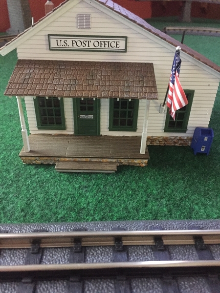
I ordered the Z-1000 and a MTH terminal block to wire all the switches to aux power. I have 9 switches for now and may add a Wye switch for the MTH dual engine shed. My curtains are made but I am going to wait until I’m done wiring under the table. I like the look of the post office so will probably add a few more of the similar buildings in that line. I am waiting on the two bridge sidings to arrive before I can proceede any further for now. 

Attachments

Images (2)
  • 3A8F3374-F258-41A8-B475-AAC2AC8CA650
  • B37F1F89-22A1-4086-B8EF-116B3E743A5C

Add Reply

Post
The Track Planning and Layout Design Forum is sponsored by

AN OGR FORUM CHARTER SPONSOR

OGR Publishing, Inc., 1310 Eastside Centre Ct, Suite 6, Mountain Home, AR 72653
800-980-OGRR (6477)
www.ogaugerr.com

×
×
×
×
Link copied to your clipboard.
×
×