RD,
I don't have lots of time to take this much further. And we certainly don't need 4 people working the same plan independently, as that can quickly become counterproductive. Even as it is... while I was doing this, I noticed DAZ took his design further... which is fine. You can get the best of all worlds.
Nonetheless, I thought it would help to introduce a slightly different way of thinking to help move your "compressed" design along... and by "compressed", I simply mean you're choosing 14x25 vs. the pure 20x40 dimension of the "exact" O-Scale version. I did this in RRT, because I've been using it since it was distributed on 3.5" disks!!!  To that end, I'm a bit of an old dog who doesn't want to learn new tricks, unless the benefit far outweighs the new learning curve. So I don't even give SCARM the time of day because it was freeware, and I never liked the fact that somebody would offer free software to undercut the value of reasonably-priced software that's been around for decades, supported well during that time, and has earned its stripes and then some for nearly 20 years. Lord knows how many times it's saved my butt, and I've designed hundreds of revisions of various "dream layouts" I've considered over the years. There's no free lunch in life, and I don't mind paying $$$ for the best products out there. But I'll admit I'm old-school in my thinking.
 ") So enough about philosophy.
So enough about philosophy.
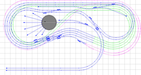
Anyway, here's the very basic RRT image-file as a PNG file:

Now here's the "new way of thinking" I was referring to earlier in my post: namely, the green track that's largely hidden remains at elevation level ZERO throughout much of the plan. It's the OTHER track (in blue and purple) that is either elevated (blue track) or lowered (purple) to adjust for clearances. This way the grades are essentially cut in half by splitting the difference between track that's lowered and track that's elevated. Using this technique, grades never exceed 3% and in some cases are less than 2%.  It's a technique I learned way back in my HO days. Since you're planning to use open grid benchwork, this approach should work just fine. And it's particularly helpful since you're compressing the plan.
Folks accustomed to building layouts on plywood platforms don't always think this way. But essentially, a good portion of what you've been thinking as the "main level" is actually now on a modest grade all the way up to a 7" elevation... which by the way is also the elevation of the turntable and track that connects over to the passenger terminal (top of the diagram). The green track is essentially either at ZERO elevation, or -1" or -2" if you need further clearance underneath the TT. The purple track actually drops at a very reasonable grade of 3% or less, and again... that can also be lowered slightly beneath the TT as required.
There's a lot for you to fill in here as far as sidings, turnout crossovers, etc.... But this shows that you can indeed design this plan with RRT. You mentioned 4.5" track centers, so I used Atlas-O track here because it fits that geometry quite nicely. Minimum curves are O-72. Then O-81, O-90, O-99, O-108... and even one curve is O-117 (flex track). Of course, you can substitue Ross or Gargraves as well. I just liked the fact that I could quickly pull Atlas-O sectional track together in RRT's library and achieve the 4.5" track centers you wanted.
Hopefully, you can follow the plan easily, since I used different track colors. I've also attached the RRT file, so you can take this further if you desire to proceed with RRT. There's LOTS left to tweak... but that's the fun part of designing one's own layout. One thing you do lose a bit of in your space compression is the whole business of open access hatches. So you'll need a couple of "hidden" ones. But the good news is you mentioned the actual room size is larger than 14x25, so you'll have room to walk around the layout. Also the TT area will have a reduced number of tracks going to a roundhouse, and the number of service tracks approaching the turntable area will be somewhat reduced. But that's part of the compromises when real-estate is compressed. Still very manageable considering O-Scale turntables with a roundhouse can be a bit overwhelming to begin with, and chew up real estate rather quickly on all but the largest train layouts.
Again... at this point, I'm not sure how beneficial it is to have 4 people working this plan -- some now using different software programs. So I'll bow out at this point. But hopefully, I've given you something to think about in terms of the elevation techniques to minimize grades. Once you get the knack of this technique, you may find that not much of the "visible track" in the plan is at level ZERO at all. Tracks tend to rise and fall as needed to achieve the various grade criteria and overhead clearances.
Best of luck... and enjoy the ride... should be a very nice track plan!
David