


I know that I'm sticking to O72 for the mainlines, I don't know in this space if I can reasonably expect to have larger curves. There will doubtless be tighter curves in the mix as well, but I'd like to leave the maximum flexibility I can for running all my equipment. ![]()
Hi John, a quick question if you have the time. 25 messages a day is a lot for you to deal with. Tim has my check and I'm on the list. What was your approx. wait time from getting on list until boxes at your front door? Our rooms are about the same size. Thanks John for your time.
Tommy
Tommy, it took a while. ![]()
I sent my original layout dimensions to Tim on 6/19/18, it took him a while to respond, and on 8/3/18 I officially placed the order. I received the benchwork on 11/21/18.
Remember, Tim was moving his shop during that time, so I suspect he lost at least a month there. Having recently moved, I can attest to how much trouble it is to get everything sorted out. ![]()
Keep up the good work GUNS!!!!![]()
Thanks Gunny, Yes, I first contacted Tim during his moving process. He asked me to contact him later. We did just that. Layout design, Room size, height, etc. was forwarded to Tim in his time frame. A week or two later I got his BW design back, all my questions answered and of course a bill. Upon remittance, I was told that I on the list. Gunny, I appreciate your time and effort.
Tommy
Hi John H.
I just ain't too bright at all. I should have thought to do that. You're so much smarter than I am.
My best regards.
Tommy
I apologize.
gunrunnerjohn posted:Tom has a tendency to make complex woodworking look easy.
It looks like he has more clamps on that corner than I own!
I try to make electronics look easy, but I'm not capable of making complex woodworking look easy.
You are not kidding on either count here! I have already given up on my woodworking skills. I will never be a Tom Tee, his bench work looks like fine cabinetry or furniture, great work! He has some really neat ideas too.
Now I'm trying to keep up with you on the electronics part and it's still quite a struggle! Will never be a GRJ either, but I am at least learning something and it's fun! Wood is also much heavier than the electronic parts and I am old and worn out, so that helps too. ![]()
You guys really do make these things look easy! That is until I try it myself... ![]()
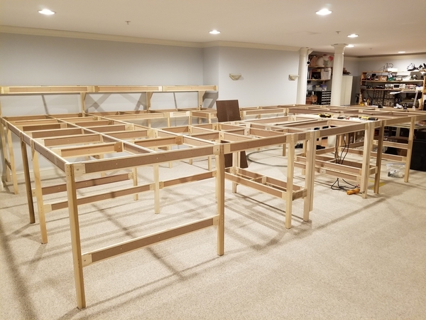
One more step along a fairly long road. Got a bunch more assembled, took a little more time as I changed my plan a bit so I had to ad-lib a bit on the assembly. All that's left is the 12 feet along the front that will have the lift-gate in the middle of it. I originally started with the lift-gate on the left, but it works better in the middle.

Attachments
Images (1)

Hey John
lots of progress , looks great !
Alex
Really taking shape now, looks great. Looks big too!
What did you change from the original plan? Just curious to see what was involved/how difficult changing things were from original plan? Your cross pieces look a bit different than mine, especially the lower ones. I had some angles ones on the lower parts.
I have some changes to mine coming up one of these days too, but I am going to have to order more stuff for the changes/additions.
Alex M posted:Hey John
lots of progress , looks great !
Alex
Thanks Alex, can't wait to get it all together and see a train run! ![]()
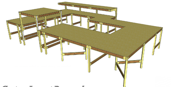
Tom, I am moving the lift-gate about three feet more centered on the front straight. This will allow my next planned expansion of a yard off the side. Here's what the original plan looked like. I'm removing some of the extra legs in the middle as I want more storage under the bench. The diagonals were only there because he was using some stuff I already had. After seeing the plan, I decided to remove those so that space under there is all open.
Attachments
Images (1)

I am happy for you, GunRunner and know you will enjoy your new table, etc. just like the first toy train you ever received!!!
The fun is just starting. ![]()
John that looks so good I think you should put a coat of paste wax on it
clem![]()
I just want to put some trains on it. ![]()
Off to the home center to get your table top, get the pieces cut at the store. Easier to handle and no mess at home. Another step closer to trains on the move.
How long has it taken you to assemble the benchwork? Was it hard to assemble? Did you have help? Thanks.
Go John, go! And most importantly: Have fun!
Andre
coach joe posted:Off to the home center to get your table top, get the pieces cut at the store. Easier to handle and no mess at home. Another step closer to trains on the move.
I'm going to have some of it cut there, I have some 4x8 pieces that will just drop on as is, those just have to come down the way they are.
TrainHead posted:How long has it taken you to assemble the benchwork? Was it hard to assemble? Did you have help? Thanks.
I probably have 7-8 hours into it. Some of the time was adjusting the plan because I wanted to move the lift-gate. No help required, it's pretty easy to manage one man. The size is 20 feet long by 12.5 on the left and 10.5 on the right. There is a 2 foot jog out in the wall and I just wrapped around it.
GRJ, when you get to laying those 072 curves, check out the clearance gauge Jim Berrett made in issue #276, Feb/Mar 2015, page 85, of OGR. It's made to give you just the right amount of room on 072 curves to accommodate running a Big Boy, that needs a 3" overhang clearance from center rail on the outside of a curve, and a 2 1/4" overhang from center rail on the inside of the curve, if you ever run 21" passenger cars. Thank You Jim for that great article.
Good idea Dave, I'll check it out.
Everyone always wants to run trains John. That is why so many carpets get track indentations. ![]() I myself have some vacuuming to do by the Christmas tree before I pop any trains underneath it. I'm still not sure what I will be running. Maybe a couple different things, lol. Looking great John.
I myself have some vacuuming to do by the Christmas tree before I pop any trains underneath it. I'm still not sure what I will be running. Maybe a couple different things, lol. Looking great John.
Well Dave, I’m content with being like John and waiting on Benchwork to run trains. I crawled on the floor too much before I got into engineering at 51 and chased around rugrats on my knees into my 40s. A nice easy to assemble table is the ticket! LOL
Looks good John. You made an excellent choice with Mianne benchwork. I found it easy to assemble. If I had any questions I would call Tim and he always replied. The system is flexible and user friendly. Hope you have all those beautiful locomotives I have seen on the move soon.
Mark Boyce posted:Well Dave, I’m content with being like John and waiting on Benchwork to run trains. I crawled on the floor too much before I got into engineering at 51 and chased around rugrats on my knees into my 40s. A nice easy to assemble table is the ticket! LOL
Yeah, a table would be nice. I've been on knees, stomach, back, side and sitting of the floor. I'd really like to have a seat at a table watching and operating. I'll have to wait and stay on the floor for a bit still. Someday. ![]()
Sure is going to be a nice space
luvtrains posted:Looks good John. You made an excellent choice with Mianne benchwork. I found it easy to assemble. If I had any questions I would call Tim and he always replied. The system is flexible and user friendly. Hope you have all those beautiful locomotives I have seen on the move soon.
Yep, a happy Mianne customer here.
Two words: no sawdust. ![]()
I still have to test upgrades, so there is a smallish carpet central. It's pretty basic, just enough to do more than run on rollers. ![]() I'm looking forward to when I can get this out of the way.
I'm looking forward to when I can get this out of the way. ![]()

Attachments
Images (1)

It's looking great John. Really nice finished train room. Keep posting, it's great to watch the progress. Is the planned layout all on one track level, or are you planning to cookie cut the plywood and have any grades ?
John, have you got a track plan cooked up yet; just wondering? Looking good so far. ![]()
Rod
I'm planning on some elevated track, but I won't be doing the cookie cut of the base. Still working on a final configuration, but any ideas are always welcome. ![]()
I'm hoping to have the couple bits I need to finish from Mianne in a couple of days so I can put the front on and get some plywood down. The liftgate is a little more complicated than the basic assembly, so I suspect that will slow me down a bit. I also have to get some pieces of different sized plywood just for that assembly.
gunrunnerjohn posted:Tom, I am moving the lift-gate about three feet more centered on the front straight. This will allow my next planned expansion of a yard off the side. Here's what the original plan looked like. I'm removing some of the extra legs in the middle as I want more storage under the bench. The diagonals were only there because he was using some stuff I already had. After seeing the plan, I decided to remove those so that space under there is all open.
Ok, I get it now. I have the same angles you show here (at somewhat different locations) and was just wondering what the differences were or if they had changed the arrangement. Of course your whole layout is different than mine, and bigger too, so I guess it would be somewhat different in the bracing.
If you want to make shelves using the lower cross bracing, a couple of 1" x 12"s side by side are a pretty good fit between the legs. I didn't want to mess with more plywood after getting the top on so I went the 1x12 route. Very easy and I did manage to find a few decent pieces at Home Depot. Got them screwed in place right away, before they had a chance to get all whopperjawed. Thinking I used some angle brackets on the shelves as well. I had a ton of those (one hole each end) left over from something years ago.
I did the shelving a few weeks after the initial benchwork. Tim put some extra holes in the legs for adding an additional shelf between the top and lower cross pieces so I had to order some more cross pieces and parts for those shelves.
You are looking good there with yours, coming along very nicely! I really like that shelf too, and the lift gate.
Guns,
My advise is to go slow, you have the rest of your life to work on your new layout, have fun buddy!
PCRR/Dave
Pine Creek Railroad posted:My advise is to go slow, you have the rest of your life to work on your new layout, have fun buddy!
But who knows how long that will be? I may get hit by a bus tomorrow! ![]()
![]()
Tom, I wanted under the layout to be as uncluttered as possible. First off, it'll make it easier to do the finish-up wiring (doing some pre-wiring before the plywood goes on), and it'll also facilitate having lots of storage under the layout. That being the case, I removed those braces and the extra leg and went with open space. I also tried to orient the lower braces in such a manner as to provide maximum access to the underside of the layout. Time will tell how successful I was. ![]()
GRJ, The open spaces are nice, I was actually kind of admiring that in some of the photos. You are giving me some ideas here as well! ![]() I ended up with 2' of shelves all the way around the perimeter (except for the ends which are open) below the layout with a wide open 2' 'isle' lengthwise, right down the middle. I actually ended up with pretty good access to everything from below for now. Maybe have to move a box or two if I want to get back in to something though. Of course the expansion still hasn't yet happened so it will probably all change then.
I ended up with 2' of shelves all the way around the perimeter (except for the ends which are open) below the layout with a wide open 2' 'isle' lengthwise, right down the middle. I actually ended up with pretty good access to everything from below for now. Maybe have to move a box or two if I want to get back in to something though. Of course the expansion still hasn't yet happened so it will probably all change then.
Another difference is I have concrete floors and a mechanics stool that lets me scoot around below the layout fairly easily. Just have to watch your head in certain places. A few cross braces still have traces of hair (my hair!) on them! ![]() With you having carpet the stool might be a little more difficult to maneuver down there and maybe hard on the carpet? Could still be handy to have though. They are about $20 at Harbor Freight. The rectangular one is a little lower than the round one. But the more you can do before the plywood goes down the better, that's for sure.
With you having carpet the stool might be a little more difficult to maneuver down there and maybe hard on the carpet? Could still be handy to have though. They are about $20 at Harbor Freight. The rectangular one is a little lower than the round one. But the more you can do before the plywood goes down the better, that's for sure.
Also, I added a string of 5m LEDs (600 LEDs) down the center space which helps me find things down there. I put a switch in a cross brace for the top, right where I go in with my stool for convenience. That works very well. You would probably need a couple of strings or more for the size of yours, but it's really handy to have while you are down there. That would be easier to install with the top off as well. It was an after though for me, after the layout had a top and running trains. Just another thought here, but I imagine you have probably already thought of all that.
The legs and lower cross braces are also good places to mount little things like light power, term strips, etc. Below is also a good place to hide things, keeps the skillet and rolling pin away from the old noggin...![]()
rtr12 posted:gunrunnerjohn posted:Tom, I am moving the lift-gate about three feet more centered on the front straight. This will allow my next planned expansion of a yard off the side. Here's what the original plan looked like. I'm removing some of the extra legs in the middle as I want more storage under the bench. The diagonals were only there because he was using some stuff I already had. After seeing the plan, I decided to remove those so that space under there is all open.
Ok, I get it now. I have the same angles you show here (at somewhat different locations) and was just wondering what the differences were or if they had changed the arrangement. Of course your whole layout is different than mine, and bigger too, so I guess it would be somewhat different in the bracing.
If you want to make shelves using the lower cross bracing, a couple of 1" x 12"s side by side are a pretty good fit between the legs. I didn't want to mess with more plywood after getting the top on so I went the 1x12 route. Very easy and I did manage to find a few decent pieces at Home Depot. Got them screwed in place right away, before they had a chance to get all whopperjawed. Thinking I used some angle brackets on the shelves as well. I had a ton of those (one hole each end) left over from something years ago.
I did the shelving a few weeks after the initial benchwork. Tim put some extra holes in the legs for adding an additional shelf between the top and lower cross pieces so I had to order some more cross pieces and parts for those shelves.
You are looking good there with yours, coming along very nicely! I really like that shelf too, and the lift gate.
I'm following this pretty closely!!!! I'll probably build my own bench work, but I loving seeing this develop.. Also please share any insights on the lift gate!! I'm getting a bit old to deal with a duck under...........
Woodson posted:I'm following this pretty closely!!!! I'll probably build my own bench work, but I loving seeing this develop.. Also please share any insights on the lift gate!! I'm getting a bit old to deal with a duck under...........
Think of those duck unders as a form of yoga. I'm 67 and now look forward to contorting my body under the train tables to get to a derailment on the far side of the layout, etc. My attitude about exercise and stretching is if it doesn't kill you, it's good for you.
Worse thing for me is to be too sedentary. Arnold
I can still crawl under the table, but that doesn't mean I like it. ![]() I'm also figuring that in a few years I may not be able to crawl under the table to get to the center. Besides, the control panel will be in the center, so I need it to be easy to get to. Also, I might have Woodson over to play trains, and he doesn't like ducking under the table!
I'm also figuring that in a few years I may not be able to crawl under the table to get to the center. Besides, the control panel will be in the center, so I need it to be easy to get to. Also, I might have Woodson over to play trains, and he doesn't like ducking under the table! ![]()
![]()
rtr12 posted:Also, I added a string of 5m LEDs (600 LEDs) down the center space which helps me find things down there. I put a switch in a cross brace for the top, right where I go in with my stool for convenience. That works very well. You would probably need a couple of strings or more for the size of yours, but it's really handy to have while you are down there. That would be easier to install with the top off as well. It was an after though for me, after the layout had a top and running trains. Just another thought here, but I imagine you have probably already thought of all that.The legs and lower cross braces are also good places to mount little things like light power, term strips, etc. Below is also a good place to hide things, keeps the skillet and rolling pin away from the old noggin...
I like the idea of the LED lighting, I'll have to do that. Let's see, 16 feet for each string. Four or five should light it up pretty well. FWIW, there are also high current LED's you can get in reels, I have them on my workbenches, they're great! They are really bright, and light up the bench like daylight. First picture with them on, next with them off. You can see by how dark the 'scope is above the light strip that the camera adjusted the light level down because it was so bright. ![]()


Attachments
Images (2)


Very nice looking John. I'm really happy to see it coming along. You will be running trains before you know it.
I think it's safe to say you have the classiest train room around.
But the look of that work shop is befitting the John we all know and admire.![]()
Good luck and have fun.
GRJ, the layout's legs may leave permanent damage to your wall to wall carpeting. Looks like you have about 32 legs that will be digging in. Your wife will have to replace the hole room if you get hit by that bus and she wants to take the layout down. Just a thought, but maybe before the layout starts getting too heavy, when you go to pick up your plywood, have them rip you two 4"x 8' strips that you can chop into 4"x 4" carpet pads. Two 8' strips will give you at least 46 carpet pads. I know you can't wait to get trains rolling and don't want to spend more time on things that will move that day farther away, but if you have a miter/chop saw and clamp down a block of wood 4" from the blade (as a stop), you can chop up those two strips in about 3 minutes.

Attachments
Images (1)

Dave Zucal posted:GRJ, the layout's legs may leave permanent damage to your wall to wall carpeting.
Dave -
What kind of "permanent damage" are you talking about?
Hi John, just a side question, do you use that solder iron on your bench for soldering track? I am looking for a good one to do my track!![]()
Santafejim,
Permanent carpet fiber damage that never rebounds like pictured here.

Attachments
Images (1)

Dave Zucal posted:GRJ, the layout's legs may leave permanent damage to your wall to wall carpeting. Looks like you have about 32 legs that will be digging in.
I've actually thought about that. I'm thinking of solutions, but I don't want big strips of wood under the legs. I was considering some of the furniture coasters to spread the load a bit.
mike g. posted:Hi John, just a side question, do you use that solder iron on your bench for soldering track? I am looking for a good one to do my track!
I actually use my old Weller 100/140W gun for heavy soldering like track, brass, etc. The Hakko is a 70W iron with temperature control, so it serves me well on the bench for wiring and PCB work.
GRJ, 4"x 4" cut from the strips you obtain from the store.
John I wouldn't do any pads under the legs, that table will be there a long time and the carpet will be replaced after the table is taken out anyway (foot traffic path). Those pads only crush a larger footprint and will get bumped every time you vacuum the floor.
CLEM brings up a good point so maybe some clear vinyl protection too. It may help keep some static sparks out of your fingers.

Attachments
Images (1)

John, A simple sumptin' that can be very helpful in carpeted rooms would be a 3 1/2" X 3/4" recessed puck with chair mat nipples fastened to the bottom of it.

When in place with adjustable levelers they will provide several features.
1.- carpet protection
2.- retain position of platform leg when some one kicks, taps or bumps into it.
3.- provide overall stability to the layout so it will not be jarred.
4.- When used for fingers of benchwork over carpet it is equivalent to fastening the leg to the floor. As below:

How many do you need?
Attachments
Images (2)

Interesting idea Tom, those look fairly simple. I just have to cut up my chair matt! ![]()
Cutting that many circles will take a bit of time, a lot easier when you have all the woodworking tools
I'll have to find my large forstner bits to make the indent for the leg. ![]()
Use a 3 1/2" hole saw to cut both the plywood and the chair mat. If you want an even soft edge you can rotate the disk on a router table with a round over bit. Use a Forstner bit the size of your adjustable foot for a 1/8" + recess. Attach the chair mat face and you are done.
Or I can drop these off to you.
Having all these tools makes it easier. I think my hole saws top out at 2". Do you do these in a drill press? How does plywood do going at all angles on a router table? I'd think it would splinter at certain angles. I don't think I've ever tried plywood with the router.
Clean router use on plywood follow the quality of the plywood. Cheap plywood with voids can yield less than nice edges. Any decent solid core plywood can router nicely. Of course always sand the finished edges with a 100 grit.
An inexpensive big box router table is OK for making disks.
I have several routers each outfitted tips I most frequently use. However, if I only could have one router my $100+/- Bosch trim router would be my choice. One hand operation, easy to use on curves and small pieces in addition to long 8' runs.
I like to round over my wire management holes and the bottom edges of all modules for safe handling.

For 3 1/2" hole saw cuts you will need a hi amp hand drill with a side handle or a drill press. I have used both, but the drill press is admittingly easier. Milwaukee hole saws last long. Drill over a back up of solid wood. Do not hit a concrete floor. Your pilot drill needs to embed it's self into a subsequent body. Sometimes it can be helpful to predrill the pilot hole.
To get the routed edges on a table I use a jig or a Phillips #2 screw driver shank and hold the disk against the bit and retard the disk from spinning too fast. Bring the bit up in stages so as to not take a big bite.
The adjustable feet are available individually at Valley Hardware in CA. Many other outlets for the feet but most others want minimum orders.
For the mat nipples I just cut them from a chair mat with the same 3 1/2" hole saw. You can buy any size mat for the amount you would need.
Nothing herein is an absolute, it's just the way I do it.
For scooting around under the benchwork this helps:


It's just a HD furniture dolly with a drop center mounted old plastic kitchen chair shell.
Attachments
Images (4)
Hey John, just wondering what your top-of-table height will be with the plywood installed? Not that it matters since we all have our preferred height. I assume Mianne may have two or more standard heights.
i like the led strip lighting for under the table, that's a great idea. Wish I had thought of something like that back in '98. That lighting on your bench looks great. Hard to beat the Weller 100/140 for track and heavy wire soldering.
Tom, really like your wire caddies. Nice size and easy to work with I would think. I also see you were smart and put up your backdrops BEFORE doing your benchwork! Another thing I wish I had done.
cheers, Rod
gunrunnerjohn posted:Dave Zucal posted:GRJ, the layout's legs may leave permanent damage to your wall to wall carpeting. Looks like you have about 32 legs that will be digging in.
I've actually thought about that. I'm thinking of solutions, but I don't want big strips of wood under the legs. I was considering some of the furniture coasters to spread the load a bit.
mike g. posted:Hi John, just a side question, do you use that solder iron on your bench for soldering track? I am looking for a good one to do my track!
I actually use my old Weller 100/140W gun for heavy soldering like track, brass, etc. The Hakko is a 70W iron with temperature control, so it serves me well on the bench for wiring and PCB work.
Thanks John, I have one of those wellers so it should work just fine!![]()
gunrunnerjohn posted:rtr12 posted:Also, I added a string of 5m LEDs (600 LEDs) down the center space which helps me find things down there. I put a switch in a cross brace for the top, right where I go in with my stool for convenience. That works very well. You would probably need a couple of strings or more for the size of yours, but it's really handy to have while you are down there. That would be easier to install with the top off as well. It was an after though for me, after the layout had a top and running trains. Just another thought here, but I imagine you have probably already thought of all that.The legs and lower cross braces are also good places to mount little things like light power, term strips, etc. Below is also a good place to hide things, keeps the skillet and rolling pin away from the old noggin...
I like the idea of the LED lighting, I'll have to do that. Let's see, 16 feet for each string. Four or five should light it up pretty well. FWIW, there are also high current LED's you can get in reels, I have them on my workbenches, they're great! They are really bright, and light up the bench like daylight. First picture with them on, next with them off. You can see by how dark the 'scope is above the light strip that the camera adjusted the light level down because it was so bright.
I like the workbench lighting idea. I hadn't thought of putting LEDs there? That would make a big difference in lighting and I have a shelf that would be perfect for those. I used a double, 600 LED reel of 5050s below the layout. I got two reels, but one down the middle was plenty. I will look around for the high current ones and take a look, for the work bench.
Edit (after looking around): Yikes, prices on the 600 LED strips seem to have gone WAY up since I got the ones under my layout!
How can you make more storage underneath the benchwork by removing the V-angled supports? I thought that you need them to support the table?
Just got caught up by reading this from the start. Nice looking room and benchwork John. I was wondering on the table height that you decided on too?
Tom
TrainHead posted:How can you make more storage underneath the benchwork by removing the V-angled supports? I thought that you need them to support the table?
Nope, the angle supports and the extra leg was just added by Tim because I had the parts and he was trying to use them. In the original design. lots of sections had no angle brackets. I asked Tim if I needed them, and he told me he was just using what I had. Since I also had more 4 foot sections, I went with the same design as other parts of the layout to allow maximum storage.
MNCW posted:Just got caught up by reading this from the start. Nice looking room and benchwork John. I was wondering on the table height that you decided on too?
Tom
The legs are 40" tall, by the time I add the deck and the 1" of foam I'm considering, it'll probably be around 42" to the top.
A note of caution. I had to do a lot of wiring under a layout where the owner had installed permanent shelving attached to the legs.
That made the job go extra long and was very awkward / painful I would caution against leg attached shelving. Working under the layout is hard enough.
Already having lots of shelving I mounted my shelving units on a series of furniture dollies. A regular poster here uses a series of red Harbor Freight carts to roll out when ever needed and provide full access to the underneath area.
Legs can also be a pain. I mounted knees on the wall and set the benchwork modules on top. When we moved I took the modules with me. The Mianne benchwork can be set on cantilevers the same way. Floor clear wall to wall:

Attachments
Images (1)

Just an FYI, I strung 100% of the buzz wiring thru the frame holes before I put my plywood top down. A whole lot easier to stand and do it than be on your back and trying to pull it thru.
For decking consider Advantech 4' X 8' X 3/4"sheets @ $30.oo +/- each. Available at 84 Lumber, select Lowe's and quality lumber yards. HD had it for a while under their brand of Ameritech.
Very strong, extremely flat and smooth. Non responsive to moisture. Certified for use in home construction to be good for four months open to weather. Very affordable.
I have been experimenting supporting it on 22" & 32" centers with no deflection in 7 years.
Also, I just added a three rail upper level to my 2 rail layout. Knowing how loud three rail trains are, as an experiment I used various deck materials. Because Advantech is so extremely dense it is the quietest structural decking material I have ever used. You can hear the difference when the train travels from any thickness plywood to Advantech. As an aside, IMO, sound systems and slower speeds make three rail wheel/track sound much more bearable.
Advantech is great stuff!
Tom, my plans include storage that is NOT connected to the layout, I've certainly already learned that lesson! I'm sure that even if I pre-wire, I'll spend lots of time down there, so I want to make sure it's as easy as possible. With the open design under the benchwork I have now, that should be pretty easy. I am planning on stringing the power wire and a few CAT5 cables around to have pre-wiring for most of the stuff. I'll still have to be down there for the interconnects, but at least it'll be a start.
John
What will you the Cat 5 for?
Bill
ogaugenut posted:What will you the Cat 5 for?
Switches, accessories, signals, lighting, etc.
I agree, John. I don’t like attached shelves either. Even after built you never know when you may need to get under there. Also, if the time comes when I can’t get under there myself, I won’t feel bad asking someone else to crawl, roll, etc into my concoction. I like the roll out storage units some folks have shown on the Forum.
I'm probably going to come up with some roll-out storage, and also in some places, just a few plastic tubs that will pull out when I need to get to them. I'm trying to orient the structure so there's maximum access from the inside and outside under the table. So far, I think I've accomplished that goal to a great degree.
This thread turned into some fantastic idea's from everyone. I'm thoroughly enjoying this, please keep the idea's coming. Only sad thing for me is i had to stop progress on my layout production until February .
Thanks John for starting this
Alex
@gunrunnerjohn, am I reading the plan correctly, basically nothing bigger than 2' x 2' squares inside legs spaced 4' x 4' ?
Alex M posted:This thread turned into some fantastic idea's from everyone. I'm thoroughly enjoying this, please keep the idea's coming. Only sad thing for me is i had to stop progress on my layout production until February .
Thanks John for starting this
Alex
John, Ditto to Alex’s comments! And I too have to wait to get to building like Alex.
Thanks guys, I'm really looking forward to completing this, even though I know it'll be a while. ![]() It's nice to actually be working on it now.
It's nice to actually be working on it now.
John D. posted:@gunrunnerjohn, am I reading the plan correctly, basically nothing bigger than 2' x 2' squares inside legs spaced 4' x 4' ?
Correct, 2x2 is the largest open space, and the legs are a maximum of 4x4 apart.
For under layout storage... a few thoughts:
Build a 1/2" plywood box the size you want with sides about 8" high
if you store cars in boxes, you can store a lot in a 2' x 3' base box (and my layout is only about 27" off the floor!)
Don't use casters or rollers.. makes the box harder to move on carpet... Instead, buy the sets of furniture moving disks at HD (multiple sets of disks are cheaper than roller or casters!) Then, drill a hole in the center and screw them into the bottom of the box in each corner....if you use a flathead screw, the plastic disk will squeeze up a but and the screw head won't snag the carpet at all! In addition, you don't lose much height, because the gliders are only about 3/4" high - much lower than a roller or caster.
They GLIDE... smoooooothly ![]()
Works great for me! (you might consider a set for an under-the-layout gliding seat too!)

... and now, back to our regularly scheduled discussion about GRJ's new layout! (Nice!)
Attachments
Images (2)
Good idea Eddie, I'd probably make them just shy of 2 feet across so I could put two side by side. Easy to build as well. ![]()
gunrunnerjohn posted:Having all these tools makes it easier. I think my hole saws top out at 2". Do you do these in a drill press? How does plywood do going at all angles on a router table? I'd think it would splinter at certain angles. I don't think I've ever tried plywood with the router.
You could always goto Harbor Freight and get the circular bores that fit your drill...
Eddie, I really like your sliding boxes! I have that low pile carpet too! Thank you for the great idea!! ![]()
One problem I have with hole saws is it's usually a PITA to get the wood puck out of the saw. ![]()
Plug removal from a one piece econo hole saw used with a straight thru bore approach can be a bit rough.
With the removable mandrel in a straight through pass, just unscrew the mandrel, remove it then you can poke the plug out.
My approach is to bore the hole a tad over half way from both sides, that way you have the protruding end to grab onto to for removal. This method provides a cleaner back face.
gunrunnerjohn posted:One problem I have with hole saws is it's usually a PITA to get the wood puck out of the saw.
That's what the 2 small holes by the center are for. Punching out the wood plug.
I know what the holes are for, but it's still a PITA, especially if you're doing a bunch of them. I suppose another approach is to use the bandsaw and a pivot and just cut a circle that way.
Eddie I really like the sliding box idea too. I imagine they would slide equally well on a painted concrete floor also. A side benefit is that you also get some protection in the event of a basement flood due to a plumbing leak or a leaky hot water heater. This is a big worry of mine because the house is plumbed with poly b pipe. Yikes! 😱 If it's overland water flood though, all bets are off!
Rod
There BETTER NOT be any floods in my basement! ![]()
Hello John, I have been watching your progress on the new layout. I believe it will be a premiere layout when you finish it. I would not worry about the carpet unless you are moving. I love this set of wheels you fabricated, you are a talented Macgyver sir. here is the proof.
BTW that is a nice townhouse. ![]()

All I have to do is find a suitable seat.
Ahh, cutting circles. You can cut sub road bed circles with a circular saw and smaller circles on a table saw.
If you encounter dexterity difficulty while cutting curved road bed with the circular saw there are even dished blades available for circular cutting with a circular saw.
Table saw small circle cutting is done with a table mounted pivot. It blew me away when an elderly deaf mute master carpenter showed me how to do this. He could not speak but was one of my best instructors.
I agree with John, The pair of top holes or even the diagonal side slots are a pain to use because you are applying uneven pressure and the plug, especially if thick, will jam. Just remove the mandrel. A vise helps. Also cutting half way from each side will give you a pull out handle.
The frequent point of difficulty with a hole saw is cost. You only want a sharp hole saw and the cost can be an issue. Plus, an assortment of them for on site use can get heavy & stolen. I have several dozen for wood and tile, Extremely helpful.
Yep, I don't want to have more money tied up in tools than I do in trains! ![]()
![]()
Check out arcusblade.com web site for saw circle cutting blades. Phone 502-495-2954. Blades start at $44. They also have trammels to mount your circular saw.
One of the uses suggested on their website is specifically for cutting curved model train track beds.
gunrunnerjohn posted:Yep, I don't want to have more money tied up in tools than I do in trains!
John, if you are like most of the rest of us train nuts, that would be hard to do! 😱
Rod

Rod Stewart posted:gunrunnerjohn posted:Yep, I don't want to have more money tied up in tools than I do in trains!
John, if you are like most of the rest of us train nuts, that would be hard to do! 😱
Rod
Yep, probably no danger in that happening if the truth were to be told. ![]()

Attachments
Images (1)

Tom, I like the rolling wire spool racks. Where did you score them?
And those cantilevered knees off your walls - excellent!
David
David98 posted:Tom, I like the rolling wire spool racks. Where did you score them?
Tom,
$30 to hold 8 rolls! I think I am going to order one! Better than the homemade thing I made! Thank you!
Only $20 on Amazon search for Gardner-Bender-WSP-100E-Electrical-Dispenser
Tom, thanks!
David
David98 posted:Only $20 on Amazon search for Gardner-Bender-WSP-100E-Electrical-Dispenser
Tom, thanks!
David
Thank you David! My adult kids finally convinced me to join Amazon Prime. It has been great Christmas shopping since I hate stores. I’ll look it up tomorrow!!!
Thanks for the tip, picked up a wire dispenser on Amazon for $20.06 total with tax and free shipping.
John a really cool way to cut plywood into sub roadbed curves, Is take your plywood (don't go cheap with plywood) to a place that makes counter tops. They can cut that plywood into curves on their CNC machine. I have not done this but my neighbor offered to do it.
Jim McGehee posted:Thanks for the tip, picked up a wire dispenser on Amazon for $20.06 total with tax and free shipping.
I'm going to be right behind you, Jim! ![]()
Tom Tee posted:For decking consider Advantech 4' X 8' X 3/4"sheets @ $30.oo +/- each. Available at 84 Lumber, select Lowe's and quality lumber yards. HD had it for a while under their brand of Ameritech.
Very strong, extremely flat and smooth. Non responsive to moisture. Certified for use in home construction to be good for four months open to weather. Very affordable.
I have been experimenting supporting it on 22" & 32" centers with no deflection in 7 years.
Also, I just added a three rail upper level to my 2 rail layout. Knowing how loud three rail trains are, as an experiment I used various deck materials. Because Advantech is so extremely dense it is the quietest structural decking material I have ever used. You can hear the difference when the train travels from any thickness plywood to Advantech. As an aside, IMO, sound systems and slower speeds make three rail wheel/track sound much more bearable.
Advantech is great stuff!
That Advantech is an awesome product! We used it to floor a 25x21 loft we put in one of our buildings. It is printed with markings for attaching at 16, 19.2, and 24 inches. Now the weather rating is no warping or separation issues for 500 days in weather. Bad thing is it will kill circle saw blades and nails spark when you shoot em its so hard! But that is a good thing also!
Jim
Moving along, all the Mianne stuff is assembled, and I just have to finish wiring the limit switches for the liftgate and it's on to pre-wiring and then putting the top on. I already have a mod in mind for the liftgate control switches, what they supply isn't suitable for my use. My gate is four feet wide, and I need a control on each side of the gate, not one handheld flapping around. The good news is, that should be really easy to do. ![]()
Attachments
Images (1)

Looks great John! cant wait to see it with the top on! Your moving right along!![]()
![]()
Not moving as fast as I like, but at least I'm moving. ![]()
gunrunnerjohn posted:Moving along, all the Mianne stuff is assembled, and I just have to finish wiring the limit switches for the liftgate and it's on to pre-wiring and then putting the top on. I already have a mod in mind for the liftgate control switches, what they supply isn't suitable for my use. My gate is four feet wide, and I need a control on each side of the gate, not one handheld flapping around. The good news is, that should be really easy to do.
Looks like the first trains might be on time!....![]() .......Pat
.......Pat
Looks good from my house!
Gunrunner at the rate your going Alex M will get his done first and you know how fast he is LOL .
Guy
It's coming along nicely!
-Greg
John: your are making better progress than I am. Have done nothing to the layout/bench work in months. But have got all he drywall complete and painted and started installing and filling shelves.
FWIW Here’s Sean’s video on his method to install switches on each side. Slide up to 8:30. liftgate switch install I’m sure you might build a better mousetrap. Maybe remote control like your garage door...![]()
Looking real good with plenty of space. I did the same and purchased pre-fab benchwork but in some areas the hills and valleys and high lines required some serious mods. The layout also has three lift up sections that simply use hinges and knife switch blades/contacts for voltage continuity. Very easy to do.
Hi John, Please keep your progress and posts published. As you know I'm at least 6 weeks behind you. Tim's moving, Thanksgiving, Christmas & New Years Holidays ain't helping me one bit. But Tim has cashed my check, and put me on the list. John, Please stay in touch on your bench work progress.
Thanks
Tommy
Thanks guys, I'm looking forward to actually having a layout again, it's been a long time coming. ![]() The liftgate control I'm thinking about will be relay based so I'm not wiring 120V around under the table, just in one place. I saw that video Ted posted, and that's another way to go, it certainly works, maybe I'll just get lazy.
The liftgate control I'm thinking about will be relay based so I'm not wiring 120V around under the table, just in one place. I saw that video Ted posted, and that's another way to go, it certainly works, maybe I'll just get lazy. ![]()
I talked to Alex, and I think I may beat him this time, he's kinda' snowed under right now. ![]()
Next I have to do some pre-wiring before I put the top on.
Looks great, John. I'll look forward to seeing something go on top of the Mianne benchwork! I'm going to give Tim a call a week or two after New Years and ask on the status of my order.
Looks good GRJ! I also saw a fellow on YouTube put switches on both sides of his lift gate. You wont have any problems doing that!
Jim
Made a bit more progress, the liftgate is done and operational. I also installed the protection panels on the side to keep fingers out of the cables. I had to ad-lib a bit on mounting the protection panels, they had a pretty lame design that only supported them from the sides. This is a 48" span, so the Masonite was flapping in the breeze. I added some wood blocks and supports to attach them on all four sides. I just used some old scrap lumber to space them out to the same plane as the legs. I'm hoping the extra blocks on the bottom I-beam help support the liftgate, all the weight of the liftgate is on those two 4 foot I-Beams, makes me a little nervous. The Masonite panels attached top and bottom and the blocks are helping support the weight on the bottom I-Beam, hopefully the liftgate lives a long and useful life.
The only remaining task for the liftgate is to add controls to operate it from both sides, the single control isn't going to do the trick. I saw a couple of Internet solutions, but I have a little problem with them. If you parallel two switches across the connections for the single switch on the control, it all works UNTIL someone on each side flips the switches in opposite directions at the same time. Then you get fireworks! ![]() While that's a remote possibility, Murphy was an optimist, so I'm not taking any chances!
While that's a remote possibility, Murphy was an optimist, so I'm not taking any chances!
Here's my latest update, the completed and operational liftgate. ![]()

Attachments
Images (1)

John:
I installed the controller for the liftgate out of sight but within easy reach just under the benchwork. Besides being convenient for me, it keeps curious visiting hands off:


Attachments
Images (2)
JOHN - When you get it completed I and others I bet would like to see your lift mechanism and wiring.
Freight Train Jim posted:JOHN - When you get it completed I and others I bet would like to see your lift mechanism and wiring.
I second that!!!
Nice work John! I hope you figure out your wiring for the liftgate!![]()
stangtrain posted:I installed the controller for the liftgate out of sight but within easy reach just under the benchwork. Besides being convenient for me, it keeps curious visiting hands off:
With a 4 foot span, my arms aren't long enough to reach that from both sides. ![]() If I want the outside switch to be disabled, that's easy to do with a simple switch on the inside.
If I want the outside switch to be disabled, that's easy to do with a simple switch on the inside.
My goal is to have the two switches, one on each side. They'll actually trigger relays in a control box that actually controls the liftgate. There will be an interlock so that when one relay is activated, the other one is locked out to avoid the dreaded short circuit with opposing switches.
John, y when you want out you could always just call the wife and tell her to hit the switch! LOL![]()
Sure, but if she's mad at me, she'll just roll something heavy in front of the liftgate! ![]()
![]()
I could see that happening. I know it would at my house! LOL![]()
You just have to make sure you don't do anything to make her mad at you! ![]()
Upset wives are a lot like “magic smoke”, sometimes it happens for no apparent reason... ![]()
Wonderful progress, John. I'm still envious at having such a large and beautiful environment in which to build. In the spirit of helpful pitfall avoidance I offer this as addendums to previous suggestions.
I would highly recommend the addition of some form of leg height adjusters that make direct contact with the concrete floor. Otherwise, when the table sinks into the carpet as more weight is added it will require constant readjustment. Direct table contact to concrete keeps kneeling to a minimum.
The sliding disc method should be employed with all things moveable along the carpet floor. Dolly wheels just create resistance and leave divets where they rest.
A concrete track plan is needed now. Before a sheet of plywood is laid, take a break and at least solidify a plan for your mainline on paper. Sidings and spurs can easily be added on the fly if necessary.
And here's my own inspired suggestion. To save many unnecessary wiring trips down under, consider the cookie cutter roadbed design table top. Feeders and other electrical connections can be threaded, soldered or fastened from up top long before the scenery is applied. Having a carpeted floor and this type of roadbed would be the ultimate in layout noise reduction.
Bruce
gunrunnerjohn posted:Sure, but if she's mad at me, she'll just roll something heavy in front of the liftgate!
And you would be stuck in the middle of your layout with nothing to do but run trains.
I don't see a problem here ![]()
The carpet has a very thin pad, and it's not a pile carpet. I don't see this sinking to any degree, but I've considered some pads under the legs, just haven't come up with anything yet. Several suggestions have been floated.
For all my storage under the layout (as you can see, it's very open under there), I plan on using carpet glides on some custom storage sleds that slide out.
I'm working on the track plan, still thinking about what I want to do, but I want to finalize something soon.
I'm not sure I'm ready to do the cookie cutter roadbed, I'm leaning toward simple here. ![]()
OK, I had a crazy idea! I was looking at possible track plans, and one thing that I don't have is space for stuff like a reverse loop in O72 or larger. I'm thinking, while I'm sure I can do something nice in this space, would it be crazy to add a little surface area?
Here's what I have, but the liftgate has been shifted 30" to the right in my current plan, it just didn't change any surface area.

I'm thinking maybe I should close four feet of the right hand opening and end up with this. That gives me a 10.5' x 8' end that's available for track. I know I'll have some issues getting to the middle, but I guess I'll have to live with that for the flexibility of having more area to work with. The good thing is, I have all the benchwork pieces to do this already.
I'm also planning on a little corner cut to allow more space at the back for the trains to make that curve.
So, what do you think? Crazy? Cool? Must have? My one concern, obviously, is access to the center of the table.

Attachments
Images (2)


John,
My advice is don't do it. When you're 95 yrs old you'll be glad it's easy to reach the center. Unless you have space for a 100' by 30' layout you will ALWAYS have to make decisions on what you can or can't fit on the layout. Keep it simple so you can enjoy everything 25 yrs from now as I don't believe you are planning to move in the future.
-Greg
Often when a reverse loop is used there is a consideration for a second reverse loop. With one loop, when a train is reversed, it must back through the loop to reverse back.
Bill
GRJ,
IMHO reversing loops are overrated. They serve a purpose, but for the amount of real estate they consume I find i5 hard to justify.
But that is just me, you mileage may vary.
I also believe access issues will arise from the enlarged table top.
Reverse loops with minimum 072 curves take up precious square footage but add greatly to running variety and interest. Both of the loops on my layout hold more than 2, 20 car freight trains in waiting while keeping the mainline open for traffic. The next best alternative without using up as much real estate would be more sidings where possible.I
Bruce
I say go for it John.
An interesting track arrangement that might work if you had room off one outside corner for your reverse loop, would be to connect it to the main layout via a wye. That would give you infinite reversing possibilities. Also a little more real estate for accessories, structures or scenery. Reach wouldn't even be that bad.
It could even work with your updated benchwork plan. And you only need one reverse loop because the wye allows you to enter from both directions.
I have to follow this thread....looking great so far and it might get me jump started.
Big_Boy_4005 posted:I say go for it John.
An interesting track arrangement that might work if you had room off one outside corner for your reverse loop, would be to connect it to the main layout via a wye. That would give you infinite reversing possibilities. Also a little more real estate for accessories, structures or scenery. Reach wouldn't even be that bad.
It could even work with your updated benchwork plan. And you only need one reverse loop because the wye allows you to enter from both directions.
I was thinking like Elliot, a WYE. Perhaps near the wall corner and build a loop table towards the column/ shop area. If not a loop, just a single line as long as the longest train you will run, which is more prototypical and requires less space. Drive in, back out. Back in, drive out. Either way. On this design, we gave up loops and ran the siding into a closet.

That would permit you drive the trains right into the shop. You could also park a train, bring it out behind one, back the first in and park that complete train. That was part of the operational reason for the above design.
I couldn't find your track plan to tinker with something, but, I think that you get the idea.
Less disruptive to the original design and permits changing direction.
Attachments
Images (1)
John looks like going to be a great layout! are you going to do any elevated tracks above regular layout? tunnels mountains draw bridges?
I say go for it, also. It gives you twice the distance before the train repeats its route in the same direction. My layout is a 7' wide U shape. I have an access hole on one side, but none on the other. Using a small work platform, I can reach the center. I will have buildings and streets in most of the hard to reach places, and they won't derail or have dead spots to deal with.
gunrunnerjohn posted:stangtrain posted:I installed the controller for the liftgate out of sight but within easy reach just under the benchwork. Besides being convenient for me, it keeps curious visiting hands off:
With a 4 foot span, my arms aren't long enough to reach that from both sides.
If I want the outside switch to be disabled, that's easy to do with a simple switch on the inside.
My goal is to have the two switches, one on each side. They'll actually trigger relays in a control box that actually controls the liftgate. There will be an interlock so that when one relay is activated, the other one is locked out to avoid the dreaded short circuit with opposing switches.
John- what about a simple set of 3-way switches to control power to the lift gate? One switch on each side in a discrete location would send power to the controller. Once the gate is moved you can flip the switch on the other side and kill power to the controls. Add a pilot light at each switch location to confirm if power is on or off. Here is a basic 3-way schematic. Several other options here.
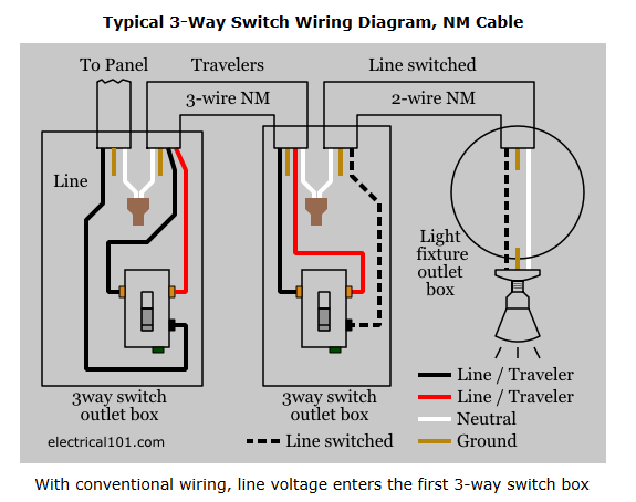
As the guru of all things electronic, I'm sure you have a great control system planned but I'm a firm believer in the KISS method.
Bob
Attachments
Images (1)

I'm still thinking on the added surface area. The worry is as stated, it'll be a big expanse that's hard to reach.
FWIW, I was considering a long single loop that actually had two reverse loops, both in the expanded area. One would be elevated and go over the first one, so you'd have two complete loops around the table and just make the loop and go down the other way. The entry and exit from each of these loops would be on opposite sides of the layout. Reversing trains would be simple in that case, just two pairs of switches between the two tracks gets it done, one pair for each direction. I'd also like to have a separate loop around that can be switched in and out to either be a separate run or contiguous with the main double loop.
Bob, my idea for the liftgate control is two relays with a simple logic interlock to avoid them ever being energized at once. The control switches will be low voltage, and I'll just lift the guts of the liftgate control and plug them into my modified control. I won't change the wiring at all to the liftgate so it can be returned to stock if desired. The only 120 volts will be inside the liftgate control box. I want dual control that are a single switch that always works, and of course I can add a disable switch if I feel the need.

Go for it John. You can stand on a small 6-7" high stool and increase your reach considerably. Long term satisfaction and operating fun over rule the exaggerated "reach" problems we talk about.![]() Anyway you will never have a derailment--probably just wiring errors
Anyway you will never have a derailment--probably just wiring errors ![]() .
.
I am considering a lift-out, probably not that large. There are 2x2 sections in the framework, so that would be a good size for the liftout. I'd make it right inside the loop so I'm not moving any track.
John, the blue line was the lift up and the red would not be filled, so you could walk in when you needed to. It would still be around the room.
I was thinking more along the lines of something like this. Either one or both could be fitted, depending on exactly what ends up in those locations.

Attachments
Images (1)

Surely those will work, I was trying to avoid ducking under.
I'd only be ducking under to work on things, so I don't mind. I like the idea of having more real estate, so I think I'll go that way.
Works for me. It's not like you're going to be ducking under all the time. My guess is you'll take your time doing things right the first time to minimize problems. You will probably be ducking quite a bit though as you build and when you add landscaping. Looking forward to following the build.
The deed is done. I now have a 10.5' x 8' chunk to do the stack O72 reverse loops, should be sufficient to get it done.

Attachments
Images (1)

Man, can you imagine having to have done that with regular benchwork? That's a big plus for Mianne and your investment has already paid some big dividends for you.
Yep, it was just bolt a few parts in place. The bonus was I already had all the parts I needed to stick it in, do it was a 15 minute job.
gunrunnerjohn posted:The deed is done. I now have a 10.5' x 8' chunk to do the stack O72 reverse loops, should be sufficient to get it done.
That’ll pay off when you send your first steamer backing down the loop to couple on to an outbound....****loads of fun!........Pat
Don't you love my little test loop on the floor? I just build the layour around it, can't wait to lose that and be able to test stuff on a real layout! ![]()
gunrunnerjohn posted:Don't you love my little test loop on the floor? I just build the layour around it, can't wait to lose that and be able to test stuff on a real layout!
Who cares!.....LOL!....let’s see the reverse loop!....I want one so bad...but I just can’t give up the real estate!....I’m jealous!....![]() ......Pat
......Pat
I didn't want to have a big expanse that I couldn't easily reach from the floor, but the realities of the space I have, that's the only way I could see getting two O72 loops at that end. Now the mainline will be a large folded dogbone, so I can run continuous on about 100 feet or so of track. Not huge, but enough to have a decent sized consist and not be chasing my tail.
John, You just showed how easy it is to alter what you buy from Tim and get it ready for a tabletop. I'm looking forward to seeing you progress.
Mark Boyce posted:John, You just showed how easy it is to alter what you buy from Tim and get it ready for a tabletop. I'm looking forward to seeing you progress.
Mark, don’t let him fool you, he’s most proud of the loop on the floor!..![]() .....Pat
.....Pat
LOL
Pat, you are quite right!!! He is!!
Hey, at least the loop on the floor is functional, don't knock it! ![]()
![]()
I'm glad I delayed putting wood on, I think I'll like this much better than what I had planned before.
I'm glad I had a bunch of spare pieces, I just dug into the inventory and had everything I needed to stick that section in. It really is easy to modify, I ended up modifying the original plan as well, I moved the lift-gate and reconfigured one of the sections to give more space under the layout. It was a piece of cake.
gunrunnerjohn posted:Hey, at least the loop on the floor is functional, don't knock it!
I'm glad I delayed putting wood on, I think I'll like this much better than what I had planned before.
I'm glad I had a bunch of spare pieces, I just dug into the inventory and had everything I needed to stick that section in. It really is easy to modify, I ended up modifying the original plan as well, I moved the lift-gate and reconfigured one of the sections to give more space under the layout. It was a piece of cake.
The reversing loops are a great idea, and a lot of fun....Grandad always said the most fun he had was during the war when he worked OT as a hostler, when man power was short he got the chance to back down a hudson on the reversing loop to couple on to a train just brought in by an electric at Harmon......anytime he told that story he’d say..”I was a big dog that day”.............Pat
Is this stiff sturdy enough to stand on it?
Hey John
You’re well on your way, and it looks great ! I’m might slow you down a bit , I’m going to need quite a few Super Chuffers and Generators. 😀
Alex
TrainHead posted:Is this stiff sturdy enough to stand on it?
Depends on your size. I was wondering the same thing so I talked to Tim a bit. He's never had anyone tell him it broke. He is aware of a 200lb man walking on a layout.
I did an experiment. I bought two legs and one beam. I put it together and sat on it. It took some work to balance it. Once 100% of my weight was on it, it shattered. I weigh 280lbs. Hope that helps.
John, wouldn’t the weight be distributed better with more legs and decking? Seems like your test just showed the strenght of a single beam, by chance a 48” beam? I wonder how a 1x4 would hold up spanning just 2 legs? And I don’t see many people putting their weight on it single beam like that.
Kinda off topic, but I agree, not a valid test. Same size dimensional lumber would fair no better in my opinion.
Of course you can shorten the beams and add more legs. This stuff is pricey enough and doubling the legs and shortening the beam would double the price.
No, a 4 foot 1x4 is not as strong because of the MDF core on the I-beam. A 2x4 would be stronger.
If you were climbing on your layout there is a good chance that at some point all of your weight would be on the middle of one beam. The way the plywood attaches wouldnt offer a whole lot of load distribution to other legs. Dont forget the additional weight of scenery and such!
I didn't do this to be exact. I did this because if it HAD worked, then I'd spend the $2k on the stuff. I'd really hate to spend this money and find out it won't support my overweight self. This was a true worst-case test and man if it passed I woulda been so happy! I actually bought 2 beams and the legs were not damaged, so I could do some more testing but I'm pretty sure 280lbs is not going to be supported.
Like it was said already, this is off topic. This is not about my layout. I hope I helped answer the question of can you walk on top of this stuff. The answer is "maybe."
Now...back on topic...hey John, you running trains yet?!
gunrunnerjohn posted:Don't you love my little test loop on the floor? I just build the layour around it, can't wait to lose that and be able to test stuff on a real layout!
That's funny to me...it beats a chalk outline on the floor....don't know why I didn't just leave the circle of track on the floor when I built my last layout. Makes me shake my head at myself. ![]()
-Greg
Tim seems to think that I could put my weight on a finished section without it breaking. I'm going to avoid that if possible, because I'm chicken! ![]() I really need it to support my layout, I'm not looking to create an elevated dance floor for midgets!
I really need it to support my layout, I'm not looking to create an elevated dance floor for midgets! ![]()
![]()
Alex M posted:You’re well on your way, and it looks great ! I’m might slow you down a bit , I’m going to need quite a few Super Chuffers and Generators. 😀
Just a bump in the road Alex. ![]()
Personally, in 50 years of layouts, I never thought of building one where I would have to climb up on it. Though I am only 170 pounds, I wouldn’t want to hurt myself at my age and with my physical problems. That said, I can see the Benchwork should hold you fine as Tim said. He would know
Looking great John(sorry been busy not checking messages lately). Its always good to dry test fitting something in, I always had some issue even if I did it. Like grandpop used to say, "measure twice, cut once." My reply was, "well, I do that but I still can't cut straight."
Its starting to really come together. Pretty soon you'll be testing how the track keeps up or drops its current, leveling off the track, getting nice even grades, all that sort of stuff. You'll get that new engine(or old new engine) out on the tracks, smoke steadily rising, and then you notice the powers not on, oops.
Dave, I'm really hoping I don't see smoke from any orifice except the smoke stack on any of my stuff! ![]()
![]()
I have been taking my time as once I finish a step, I really don't want to go back and repeat it!
gunrunnerjohn posted:Dave, I'm really hoping I don't see smoke from any orifice except the smoke stack on any of my stuff!
I have been taking my time as once I finish a step, I really don't want to go back and repeat it!
Yeah, it really is a PITA when you are doing something, get it all set, and then you have to take everything all back apart. I have visions of my Uncle Eddie(God bless him) working on my grandfather's Ford Golden Jubilee tractor trying to figure out what's wrong with it. He had pulled so much stuff apart the first fee times that he just left it open to the bare bones to work on it. He had gotten that working back to better than it was first day off the factory floor. Well, now the tractor has had a few bad years of my sister's boyfriend trying to work out what isn't working on it(he's a mechanic, can fix all sorts of things, my uncle was a wonder with vehicles, tractors, and pretty much everything else). Needless to say I wish my uncle was alive because he would either fix it or bury it.
Hopefully John you won't have any of those sorts of issues. Of course trains aren't tractors, but they can be temperamental at times. May that never happen(unless you forgot to turn the power on like some have done).
I disagree that reverse loops are over rated. Racetrack track plans soon become dull. Having the ability to change direction or even hold a train in the loop while other things are taking place adds to the fun. Of course those of you with outbuildings dedicated to a layout or basements the size of a high school gym will have a different opinion, in my small crappy basement the linear solution with loops at each end and in the middle provide endless variation.
Once I lay in the reverse loops, I plan on one additional loop all the way around. It will have switching to allow me to either join it to the big folded dogbone for an additional loop, or to run it as a separate independent loop that doesn't connect to the main loop. Finally, there will be the sidings for industry and the like. I have in my future (near future) plans to add a yard off to the left side down the wall of the basement extension. That will give me more parking space for staging. It also gives me something to do after the main track plan is done. I won't say "until the layout is done", we all know that never happens. ![]()
gunrunnerjohn posted:Once I lay in the reverse loops, I plan on one additional loop all the way around. It will have switching to allow me to either join it to the big folded dogbone for an additional loop, or to run it as a separate independent loop that doesn't connect to the main loop. Finally, there will be the sidings for industry and the like. I have in my future (near future) plans to add a yard off to the left side down the wall of the basement extension. That will give me more parking space for staging. It also gives me something to do after the main track plan is done. I won't say "until the layout is done", we all know that never happens.
Excellent thinking GRJ! Exactly what I plan to do when I get a little more space in the train room! Actually considering a double main loop with a crossover and option to run around the room. May be a challenge using Fastrack though.
Jim
John, Even with months of planning, RRTrack designs and input from many, it still evolved once I began building, using fastrack left me without many options for on the fly custom bends, but it all began to take shape when I laid it down, and wound up with a reversing elevated section which added that function and gave me a lot better layout for multiple operations.
I just wish I had more real estate for a larger yard than I got, fortunately, switching is not a huge part of my fun.
I really like the way you optimized and kept the 072, I just couldn't get that much space and wound up with 060 and 048 main lines.
I have too many things that run on O72 to sacrifice that part. ![]() I'm working on the track plan in AnyRail, I want to get the main loops figured out, then add the rest of the industry sidings, etc. Of course, I want to leave room for scenery and buildings.
I'm working on the track plan in AnyRail, I want to get the main loops figured out, then add the rest of the industry sidings, etc. Of course, I want to leave room for scenery and buildings. ![]()
I'm sure once I actually start laying track that it won't end up exactly like the plan.
gunrunnerjohn posted:I have too many things that run on O72 to sacrifice that part.
I'm working on the track plan in AnyRail, I want to get the main loops figured out, then add the rest of the industry sidings, etc. Of course, I want to leave room for scenery and buildings.
I'm sure once I actually start laying track that it won't end up exactly like the plan.
Good thinking again GRJ! I decided on 072 on the outside main right away. Not only will it allow bigger engines, but it just plain looks better. Its easy for me to not have a track plan at all. Just keep moving it around until I like something. Then move it again. Sooner or later it will all come together. That's the best thing about Fastrack!
Jim
I have an idea of what I want, once I lay it down in the CAD, I'll see if it's realistic to have it. ![]()
Your on the right track John (pun intended). AnyRail was my third and last program and by far was the the easiest to use, at least for me. Like others have already said it gets you started. Good thinking sticking with the 072 curves. There's much more flexibility with motive power and passenger cars. Even after I started to lay the track I still tweaked the plan the way I wanted to. In the end mine looks kind of sorted like my AnyRail plan. ![]()
I put O72 on my 3 rail highline as I had to go around 2 tight curves on my T shaped line to stay near the walls. I thought that it would be big enough as many engines list it as a minimum curve. It does work and one of the curves is inside a tunnel so it won't look too bad. However if I had more room, I would go bigger. When I run, I always slow down on those 2 curves as it appears the equipment is on the edge of derailing. It doesn't, but it looks like it wants to. Our grandson also slows down there without being told to. I installed a retaining type wall inside the tunnel to protect from derails.
I have to believe many posters that state, go with as big of curves as you possibly can.
I recall one of John Armstrong's layout books discussing "cosmetic curves" and using landscape and structures to "hide" tight curves (which 072 is with scale equipment) . I won't be building a layout, but I hope John that you can incorporate those into your layout.
Well, one of the O72 reverse loops will be under the other one, that sort of hides it. ![]()
Engineer-Joe posted:I put O72 on my 3 rail highline as I had to go around 2 tight curves on my T shaped line to stay near the walls. I thought that it would be big enough as many engines list it as a minimum curve. It does work and one of the curves is inside a tunnel so it won't look too bad. However if I had more room, I would go bigger. When I run, I always slow down on those 2 curves as it appears the equipment is on the edge of derailing. It doesn't, but it looks like it wants to. Our grandson also slows down there without being told to. I installed a retaining type wall inside the tunnel to protect from derails.
I have to believe many posters that state, go with as big of curves as you possibly can.
Sounds like you have a built-in prototypical "speed restriction": not really a bad thing, is it?
And it sounds like your grandson is a natural-born engineer. ![]()
Mark in Oregon
Strummer posted:Engineer-Joe posted:I put O72 on my 3 rail highline as I had to go around 2 tight curves on my T shaped line to stay near the walls. I thought that it would be big enough as many engines list it as a minimum curve. It does work and one of the curves is inside a tunnel so it won't look too bad. However if I had more room, I would go bigger. When I run, I always slow down on those 2 curves as it appears the equipment is on the edge of derailing. It doesn't, but it looks like it wants to. Our grandson also slows down there without being told to. I installed a retaining type wall inside the tunnel to protect from derails.
I have to believe many posters that state, go with as big of curves as you possibly can.
Sounds like you have a built-in prototypical "speed restriction": not really a bad thing, is it?
And it sounds like your grandson is a natural-born engineer.
Mark in Oregon
Mark, Good points about Joe built in speed restriction and his grandson's attention to what is going on!!
gunrunnerjohn posted:Well, one of the O72 reverse loops will be under the other one, that sort of hides it.
Got to like a fella with a sense of humor.![]()
My new layout will have the Mianne lift-bridge, and it'll make access to the center of the layout much easier, especially as flexibility starts to wane in my later years. However, I have identified an issue with the bridge, specifically the hazard to my head! If you're under the bridge and misjudge the height as you duck under, you can whack your head on the I-beams. The edges are actually very sharp and square, and I have a couple of cuts on my noggin to prove it. I considered rounding the edges, but that would only be a partial solution, so I dropped into my local Lowe's store and picked up some 1/2" split pipe insulation. A perfect fit, and a nice padded place for my head to land on, no more cuts! ![]()

Attachments
Images (1)

Hi Gunner, Tommy Thompson here. Have followed all the reply's for many months on your progress. Well Done !! I made a brief mention back on page 1 or 2 that I was a few months behind you in ordering and was then waiting on Tim to build. Tim called today and is shipping on Monday 02/04. Its great when a plan begins to unfold. Thanks for all of your comments and updates. I listened to all of them.
Best regards
Tommy
gunrunnerjohn posted:…. A perfect fit, and a nice padded place for my head to land on, no more cuts!
I came to the post expecting more to see. I guess we all have our..... issues?
I'd laugh at you for this but I've done it too many times to remember.
…..Wait. ![]() What were we talking about?
What were we talking about? ![]()
Tommy, glad you're getting your benchwork soon. I'm working on the track plan so I know where to do the pre-wiring. Then I'll start putting the top on.
gunrunnerjohn posted:My new layout will have the Mianne lift-bridge, and it'll make access to the center of the layout much easier, especially as flexibility starts to wane in my later years. However, I have identified an issue with the bridge, specifically the hazard to my head! If you're under the bridge and misjudge the height as you duck under, you can whack your head on the I-beams. The edges are actually very sharp and square, and I have a couple of cuts on my noggin to prove it. I considered rounding the edges, but that would only be a partial solution, so I dropped into my local Lowe's store and picked up some 1/2" split pipe insulation. A perfect fit, and a nice padded place for my head to land on, no more cuts!
Great idea, John. I'm off to Lowe's tomorrow. ![]()
gunrunnerjohn posted:Here's what the original plan looked like. I'm removing some of the extra legs in the middle as I want more storage under the bench. The diagonals were only there because he was using some stuff I already had. After seeing the plan, I decided to remove those so that space under there is all open.
John, sorry I missed this back in December. Have you noticed anything negative about removing those center legs? Is there any weakness in the center as a result? Thanks.
Dave, Thank you for looking at John's topic and asking the question. I've been following from the beginning, but totally forgot John said he was going to do away with some of those legs.
John, I am curious too how you think that will work out!
DoubleDAZ posted:gunrunnerjohn posted:Here's what the original plan looked like. I'm removing some of the extra legs in the middle as I want more storage under the bench. The diagonals were only there because he was using some stuff I already had. After seeing the plan, I decided to remove those so that space under there is all open.
John, sorry I missed this back in December. Have you noticed anything negative about removing those center legs? Is there any weakness in the center as a result? Thanks.
No adverse effects I can see. Tim actually just did it that way to use as much of the benchwork pieces that I already had. I specifically asked about that and he said it's no problem to remove them. Since I had more 24" and 48" pieces, picking up a little hardware was enough for me to change it around. Much of the other side and back don't have the legs in his original design, so it's hard to believe these were required.
Great thread on the Layout. I finally read the whole thing. Great work and ideas.
I used Sievers Benchwork to build a 12 X 14 layout. I laid 1/4 inch pegboard on it instead of plywood, and indoor/outdoor carpet on top of that. I routinely walk on the layout to get to some shelves and cause no ill effect. 180 lbs. I did the pegboard because it was flat compared to the plywood at Home Depot and I can poke a wire anywhere I want with holes on a 1 inch grid. And I did a lot of that.
I agree on liking reversing loops. I have a reversing upper level and lower level on the 048 loops that make for some interesting play time. The ramps are around 9 ft in length using MTH risers with the Fastrack tops on them. If I start the engine out correctly, it runs up and down and repeats without intervention. Then I have an 060 and an 072 loop as well, all of which are connected by switches.
Interesting idea Chuck, I'd like to see a picture or two of your layout.
Chuck, I’m also curious, especially how you are supporting the upper level loop. I seem to remember reading about your using pegboard.
John, thanks for the reply to my question.
 I used the MTH risers, graduated and fixed height, that come with the Fastrack clips on the top. I used some sort of self tapping screws about an inch tall to fasten the base of the riser to the pegboard below the carpet where advisable. Here is a close picture of them. I like mostly track and wire as you can see.
Attachments
Images (1)
BTW, I just step on the Fastrack with slippers on to walk on the layout...somewhat infrequently. And there are two access holes in the middle of the layout that you cannot see well...they are 2 by 4 foot openings. I cannot afford to gain weight and keep using them.
Add Reply
Sign In To Reply
