Hi all!  I'm sure this question has been asked many times and i am sorry to post it again but i am lost! 

I have a layout, L shaped approximately 20 x 16.  The basic shape has been down and i have small cw 80 transformer with one lock on attached.  I have tubular track and i only run conventional although I just got a lionchief set that i can't wait to run.  Anyway, the basic shape is there now.  I have a cw80 transformer attached with one lock on and every so often I run a train around.  Simple and easy.  I have several 022 switches in place where i will add sidings and a couple of accessory tracks in place.  I have not touched my layout in over a year because I started a new job and in the summer I spend all my time on the water.  Now that winter is here, yeah Ohio, I want to work on my layout.  I will be attaching a kw transformer to the layout so i have two questions.

1) I understand that with a layout this size I will need to add more power.  I have a ton of extra lock ons.  I also have a few terminal blocks that I bought at the hardware store too.  What the best way to add the power from the transformer to the rest of the layout?  i know that every 6 feet or so I need to add power.  Do i run a wire from the transformer to each lock on or can i run from lock on to lock on?  I saw a video from Lionel about running a bus wire but I am not sure how that would work.  I do like that idea because there was something in there about adding a toggle switch to the sidings to switch out different engines when i park them which i do want to do. 

2) Even though the switches do not have all the sidings in place and i have it so that the train can switch from one track to another (i only want to run one train around the layout at a time) I know that I want to add constant power to the switches via the fixed voltage plug.  I have the plugs but where do i connect it to? Do i run the wire from each switch (i have 10 currently, i could add more) back to the transformer?  Do i run the bus line thing again?  Terminal blocks?

I appreciate the help.  I know this is easy for some people but for me it is not always the easiest especially because my job does not let me come home every night so i don't always get to work on stuff.  Please don't make me feel stupid! Thanks!

Dave

Original Post

Replies sorted oldest to newest

We were all newbies at the beginning, so don't feel bad and no pressure. It's always good to ask questions.

IMHO, whether you use bus wires or terminal blocks is a matter of personal preference. Bus wires are just long wires (typically 14 gauge) from each output of your transformer (+ and -) that run underneath your layout and roughly mimicking the shape of your loop and come to an end back near your transformer without connecting to anything. You would then run feeder wires/power drops (16-18 gauge) spaced around your loop every few feet or so from the bus wires to a lock-on. The feeder wires connect to the bus wires using special connectors such as "suitcase" or T-type connectors. You would not want to wire from one lock-on to another. Using this method, power is transmitted to every part of the loop, so that there are no dead spots.

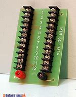
Assuming you have a terminal/distribution block similar to the one pictured below, the alternative method is to wire your transformer directly to the main red and black inputs on the terminal block (using 14 gauge wire) and then run paired 16-18 gauge wires from as many outputs on the terminal block as you need, to your lock-ons spaced around the loop. This method will also provide power to all parts of your layout.

In either case the feeder wires are typically run up from the bus wires or terminal block outputs through small holes drilled in the layout base. 

These terminal blocks come in 12 and 24 output varieties based on the size of your layout.

MTH 12 PORT


Attachments

Images (1)
  • MTH 12 PORT
I have a ton of extra lock ons.  I also have a few terminal blocks that I bought at the hardware store too.

It sounds like you're all set. Only use lockons where you need them, there is no set rule. If you want to go every 10-12 track joints, that should be plenty.

Use one wire from the transformer to each of your terminal blocks / barrier strips for distributing around the layout.

Track Jumper Feeder Diagrams A and B

I have several 022 switches in place..  ...I have the plugs but where do i connect it to? Do i run the wire from each switch (i have 10 currently, i could add more) back to the transformer?  Do i run the bus line thing again?  Terminal blocks?

You can daisy-chain or home-run(or a combination) the plugs to your accessory voltage. With the KW, you only have a choice of 6v(too little) or 20v(too much) fixed voltages, so if you really are running just one train, use A-U for the train and "B" for the switches, & fine tune lever B for optimum switch performance.

Here is the full 022 manual showing typical Fixed Voltage Plug connections:

Attachments

Images (1)
  • Track Jumper Feeder Diagrams A and B
Last edited by ADCX Rob

Providing 14v (from a separate transformer for track power) to the switches via the fixed voltage plug-in on switches is an ideal arrangement. Be sure the two transformers are "in phase."

This method provides full throttle track power to locomotives without draw-downs for switches (or accessories) and delivers accurate 14v to the switches.

I used terminal blocks on my layout to distribute 14v to 11 switches (a mix of Lionel and K-line O42 switches) from a separate MTH transformer; primarily because I applied 18v for track voltage from a Lionel 135w "brick" to drive TMCC-equipped locos . Never had a problem.

Mike Mottler   LCCA 12394

Add Reply

Post

OGR Publishing, Inc., 1310 Eastside Centre Ct, Suite 6, Mountain Home, AR 72653
800-980-OGRR (6477)
www.ogaugerr.com

×
×
×
×
Link copied to your clipboard.
×
×