Mark Boyce posted:Aegis21 posted:Mark Boyce posted:I like having a purpose for my railroad, such as hauling coal or logs from point A to point B. Some folks are quite happy with the purpose of just running trains. Either is great! It depends on what you want to do.
I would like to have a purpose for the railroad. Not totally sure yet what that maybe, but coal is definitely on the short list of mine. And sometimes just having a train run is nice, kind of like setting on the porch and hearing the diesel horn off in the distance and anticipating the train coming past the neighborhood.
I always have a continuous run ability to use on occasions I want to break in a new engine or just run trains. You may have seen that discussion early on in my topic. A true point to point only layout was suggested. Most people don’t go for that.
Hi Mark,
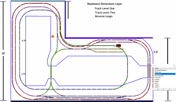
I did read your entire layout planning topic. My preference at this time is the double loops. I am not sure if that will change in time when I get to see more layouts in a functioning setting. At this time I am wondering, and questioning the two main line set up. I know it adds a lot of long runs and track, however the loops get messy and cluttered and limits other aspects. I hope you and others with more experience than me (which would be almost everyone) will chime in with comments and any reasons one way or the other.
Thanks John