Sorry about the pic being cutoff, still new to scarm and posting
Thanks Jan and Bob Great ideas and advise! I will be looking at these options as I start to formulate what the railroad will do as its functions. ![]() Had thought of, or seen a reversing siding till now. I also like the sweeping curves, it sounds like those lend more realistic views of a real railroad.
Had thought of, or seen a reversing siding till now. I also like the sweeping curves, it sounds like those lend more realistic views of a real railroad.
THANKS a ton!
John
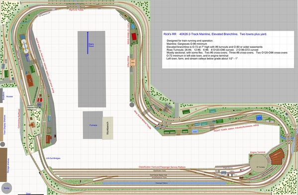
AEGIS21, you might be interested in my design thread for Rick's Layout which I did for Rick. I noticed the similarity in shape, and thought you might want to scan this discussion for ideas. Rick's layout space is larger, and access to the space is different, but many of the ideas and considerations would apply to your space as well. Rick went with a double-track plan with cross-overs, with an elevated third mainline. There are two town areas and a large yard, so trains can originate and service industries that make sense for train operation. -Ken
Attachments
Thanks Ken! I see the resemblance in shape. Hope I can get something half as good and I will be thrilled!
Jan posted:
I like Jan's double-track concept. And concur with his suggestion on using the largest diameter than can fit.
I would drop the idea for the jut-out in the center, as you will need space for operators and builders to move around comfortably. The 3'-wide aisle width is good, but you need more than just aisles IMO, you need space for two or three operators and visitors to move around the layout. So retaining a larger open operating and train-watching area in the center will add value and enjoyment, more so than the added scenery or industry area.
Hi Ken, Great advise on the opening/aisle, I was looking at possibly rounding that center jut-out and sweep it back some. Not sure how to make a curve baseboard in scarm, or if it is even possible. ??? I also like Jan's double track and sweeping curves. I am looking at Rick's posts as you suggested and read the opinions on prototyping real railroad versus "running Trains around" From what was written I am leaning towards Rick's concept of serving industries and point to point operation with leeway to let imagination and nostalgia run amuck, LOL
Thanks
john
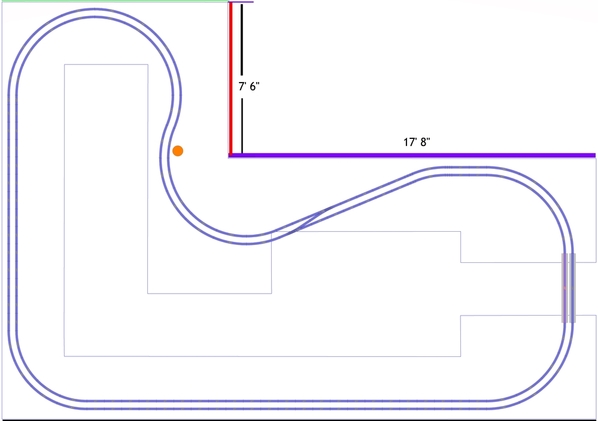
Aegis21 posted:Here is an updated, more precise drawing.
I don't see the pole as a major problem as long as we know exactly where it is, but the wall dimensions still seem off. The Green wall at the top is now marked 10' 10" and that is where the Red wall is. The Purple wall in the center is marked 18' 6", but they don't add up to the 28' 6" length of the Black wall on the bottom. So either the Green wall is really 10' and the Red wall needs to be moved to the left or the Purple wall is only 17' 8" to make the total length 28' 6".
On another note, I've always assumed you'd want a dual main, I just thought it was too early to offer layout suggestions. I added the O72 track and O54 reversing loops just to provide some perspective of the space.
While I agree with using the widest cures you can, I wouldn't let that influence what I'd "like" on my layout. My first inclination is list everything I'd like and then see what will fit with different track sizes and configurations. But then I don't really care too much about how my engines look running around when it comes to engine overhang. ![]() If I need to use O54 or any other size curve to get what I want on the layout so be it. I do shy away from anything tighter than O36 even though all my equipment is rated for O31.
If I need to use O54 or any other size curve to get what I want on the layout so be it. I do shy away from anything tighter than O36 even though all my equipment is rated for O31.
And while I also agree with the idea of wide aisles, that really depends on how many people you expect to be involved in operating the layout at any given time. I've visited 2000 sf layouts where the aisles are 36" throughout and was able to move around easily enough. Of course, that was just 5 adults walking around looking at various elements and not operating. If you plan to have grandkids playing engineer, then deleting the 6' wide peninsula might be a good idea, but that's completely up to and I think you're far from making that decision. My inclination would be to leave it in, but design around it unless you need to use it for something specific.
Along the same line, I agree with Carl's suggestion to use 30" deep decking and only add the extra 6" where you need to, like to add a yard, passenger station, etc. If you place track close to the wall and elevated, 36" can be too far to reach to lift a heavy engine or repair something.
John, to round things, you just "insert" new points and place them where you want them. However, I would keep the current baseboard as a template as you design and then modify the baseboard as you get closer to the final design.
Attachments
DoubleDAZ posted:Aegis21 posted:Here is an updated, more precise drawing.
I don't see the pole as a major problem as long as we know exactly where it is, but the wall dimensions still seem off. The Green wall at the top is now marked 10' 10" and that is where the Red wall is. This is correct!
The Purple wall in the center is marked 18' 6", but they don't add up to the 28' 6" length of the Black wall on the bottom. So either the Green wall is really 10' and the Red wall needs to be moved to the left or the Purple wall is only 17' 8" to make the total length 28' 6". Purple Wall is 17'8"
On another note, I've always assumed you'd want a dual main, I just thought it was too early to offer layout suggestions. I added the O72 track and O54 reversing loops just to provide some perspective of the space.
While I agree with using the widest cures you can, I wouldn't let that influence what I'd "like" on my layout. My first inclination is list everything I'd like and then see what will fit with different track sizes and configurations. But then I don't really care too much about how my engines look running around when it comes to engine overhang.
If I need to use O54 or any other size curve to get what I want on the layout so be it. I do shy away from anything tighter than O36 even though all my equipment is rated for O31. AGAIN Great Advice!
And while I also agree with the idea of wide aisles, that really depends on how many people you expect to be involved in operating the layout at any given time. I've visited 2000 sf layouts where the aisles are 36" throughout and was able to move around easily enough. Of course, that was just 5 adults walking around looking at various elements and not operating. If you plan to have grandkids playing engineer, then deleting the 6' wide peninsula might be a good idea, but that's completely up to and I think you're far from making that decision. My inclination would be to leave it in, but design around it unless you need to use it for something specific. I will leave it in for now and see how track and scenery dictate the final shape with always keeping an eye on comfort. Since I am new to the area and virtually do not know a soul, I do not anticipate a huge crowd. lol
Along the same line, I agree with Carl's suggestion to use 30" deep decking and only add the extra 6" where you need to, like to add a yard, passenger station, etc. If you place track close to the wall and elevated, 36" can be too far to reach to lift a heavy engine or repair something. These are the tid bits of info I desperately need. Since never building or working with a large layout, I don't know what I don't know.
Attachments
Ok this seems to have a life of its own! With the additional 10" in the L area. I need to move the one aisle over a foot to keep that section to less than 36" as recommended. It will be 34" with this revision. I also put in several points to round or shape at a later time if needed/wanted.
Still having trouble posting a full jpeg they all get cutoff. Is there a setting I need to change in scarm when exporting to jpeg?
Thanks again!
John
Attachments
John,
This seems to be a bug in SCARM (I need to contact Mixy about it), so I don't use the Export option. If you hit the "Fit To Screen" menu button, you'll notice that the "fill" is based on the baseboard and not all the elements in your project. I believe this is the reason some of the jpeg image seems to be cut off.
Here's what SCARM "fits"...........
Here's what's actually in the project..........Note the green rectangle.
Instead, I use the Windows "Snipping Tool" to snip as much or as little of the SCARM image as I want. To find the tool, simply hit the Windows key and start typing "snipping tool". When you see it, you can pin it to the Start bar. It's really a handy tool for capturing anything on the screen and lets you mark it up to point out items of interest, like what I circled in Red.
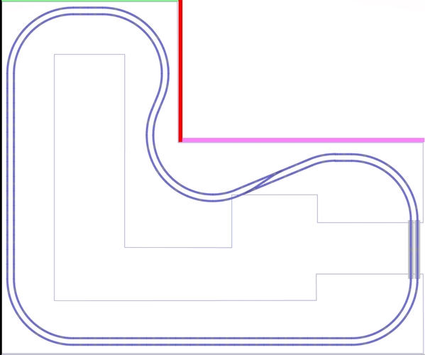
And since I'm posting, I fiddled a bit with Jan's rendition to fit the new space. Note I simply added some straight tracks and another crossover just to point out that you need both in order to travel between inner and outer runs.
Attachments
Attachments
I forgot to add that another reason I don't like the SCARM jpeg is because there are no rulers or grid lines.
Dave's right about the lack of ruler dots in the picture. I converted the original bitmap (bmp) exported by SCARM to a jpeg so I checked the original bmp to see if they were eliminated in the conversion. No dots in either.
Both Dave and I use a single crossover to establish track spacing of the loops. Your final plan will have crossovers to meet your wants,
Jan
I sent a note off to Mixy about the jpeg problem that I think is caused by the "fit" process. I didn't mention the ruler or grid problem, but I did point him to this thread, so hopefully he'll see this discussion too.
My dad always said everyone could be a good bad example. lol Hope this helps get jpeg resolved
In the mean time I did find snippet thanks to all the Huge help from Dave
Attachments
Hello All,
Another question I have is how close can two tracks be on straight and curved sections? I will be using Gargraves track and Ross switches. Using Gargraves how can I replicate Jan's track work of my layout? Keeping the two lines parallel through curves. I tried 80" 89" 96" curves with varying degrees of failure.
Thanks again!
Like Jan, I use a crossover to keep my mains parallel. The key is configuring a crossover with the desired amount of separation. Generally folks seem to agree that 3.5" separation is the minimum for yards where trains move slowly and 4.5" for mains. Curves can be a different story depending on equipment being run. There is the engine overhang on the outside of curves and the rolling stock overhang on the inside of curves. Where they both meet on a curve determines the minimum amount of separation for your equipment. Of course, it depends on the look you want too.
In Jan's example, he used Atlas #5 switches, partly because they have a 4.5" separation. However, since you want to use Ross switches with GarGraves track, the closest you can get is the Ross 11° switch with a Ross 10 straight for a 5" separation without cutting track. I believe you can substitute any Ross # switch and get the same result.
The placement of the switches doesn't matter because you'll only include the ones you need in the final design. I added a Crossover Layer with some examples for you to look at. Note the separation, but also note the footprint. That often plays a role in which configuration you actually use.
Finally, I tried using GG O96 (Layer 96-89), O89 (Layer 89-80) and O80 (Layer 80-72). The photo shows the 80-72 results. One thing to remember is that the curve going up into the "L" becomes an inside curve, so it uses the tighter curve. This applies to the curves by the rightmost crossover. There are also 2 pieces of Flex Track as well as some places where tracks need to be cut. There's really a lot of trial & error getting things to line up for cutting.
One of the drawbacks to using GarGraves is the lack of the smaller fitter pieces that both Atlas and FasTrack have. However GarGraves is fairly easy to cut and bend. In fact, some builders have used nothing but flex on their layouts.
Attachments
Thanks Dave Again! Cutting track is not a problem, just knowing what the clearances should be a huge help. I admit to having a tendency to have track too close. The instruction on the curves with examples is awesome.
Also I am hoping these loops can have sidings and spurs for industry use. Also someplace to reverse would be nice, however from what I have read that is probably out of the question with my space.
Thanks for the info and layout file as always, it is greatly appreciated.


