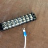
I've been enjoying the posts of jhainer, among others.  He writes as his tag line/signature, "I would love every aspect of model railroading if it wasn't for the wiring and soldering."  That got me to thinking: I've spent 2.5 years building a 11' x 12' bedroom-sized layout. It's nearly completed, and I've never picked up a soldering iron once. Every connection (track feeder lines, connection to accessories, ...) is made through what Radio Shack calls a "dual row barrier strip" (below). This is probably too expensive a solution for large basement layouts, but with about 80 of these devices, I've made all my connections. The good news is that they're easy to re-use on the next layout, so it's a long-lasting investment. They're also flexible, in that additional wires can be added easily without disrupting existing connections. 

I realize that some more adventurous modelers use their soldering iron inside locomotives and for other repair work, but I just wanted to mention that a layout can be built in a very modular, flexible manner without needing to touch the dreaded soldering iron. 

Attachments

Images (1)
  • dual row barrier strip
Original Post

Replies sorted oldest to newest

Bob,

First off, your layout and the videos that you've created are a real treat and have been both informative and inspirational. Thanks for taking the time to create and share those.

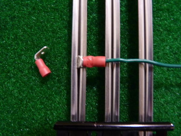
I'm with you regarding the solderless approach. Our last 4 Christmas layouts have used barrier strips, suitcase connectors and crimp-on spade lugs for all of the wiring connections and junctions. I reuse almost all of it the next year on a new layout.

Mike


I have often wondered why it is the "dreaded" soldering iron. Now, don't get me wrong, I do not build fine-scale brass models with soldered-on exquisite details, and I can't say that I enjoy soldering, but it is just another skill for your mental toolbox, does a better and more compact job of attaching things sometimes than most anything else, and is devastatingly cheap.

So, when I hear guys say "I can't solder", I wonder if they have ever really tried? It is not complicated, but, like any other skill, it must be acquired by practice - but not much of it. (I did have a father who taught me things like this, I'll admit.)

Depending - oh, yes! - on where you are (workbench - good, under layout - bad), what you are doing and your experience (again, not much), soldering can be fast (including setup), easy, clean, durable and almost free. It just isn't always the "best" way (see "under layout", above).  I also use solder melted on the stove to cast small metal parts. 

I just use alligator clips for most of the connections. 

I ran nine large diameter solid wires the length of the layout with all of the insulation stripped off.  The wires are parallel and about 4" apart for easy access and to prevent shorts with the alligator clips.  Eight of the wires were electrically connected to each of the eight terminals on my postwar ZW through pigtails and 6 amp circuit breakers and TVS diodes.  The ninth wire was a switched wire for building lights. 

Each of the accessory toggle switches on my control panel is electrically connected to a stud under the layout.  The other leg of the toggle switches are all tied together and to ground. 

When I add or change a powered accessory, all I do is attach one of the alligator clips to one of the hot wires (usually B or C, since they have relatively fixed voltages) and attach the other alligator clip to one of the switched studs.

When I add a lighted building, I do the same except that instead of attaching one of the alligator clips to one of the switched studs, I attach the alligator clip to the ninth wire (which is also controlled by a switch on the control panel).

I have two loops of track.  I use the 'A' and 'D' hot wires to power each of the track loops.  So when I want to add another drop, I just use the alligator clips to attach to the 'A' or 'D' hot wire and the corresponding 'AC' or 'DC' ground wire.

Troubleshooting shorts is easy.  For example, if I have a short on the 'C' circuit of the ZW, I just remove all of the alligator clips on the 'C' wire and then re-attach them one at a time until I find the short.  How simple is that?

I run TMCC, Legacy, and DCS on my layout and all run fine.

The wiring is not very picturesque, but it is extremely functional.

Earl

As a few others have said,I don't understand the problem with soldering.  There is nothing wrong with using barrier strips or other connectors, but sometimes(many times) cheep as free solder is the way to go.  It may be that my father had me soldering PCBs when I was 5 or 6 years old, but I don't really know what the trouble is with <Heat, apply solder, repeat on next connection.>  sure it is dreaded if working surface mount components with a 15w iron, but for track wiring a 250W weller gun will blast through it in no time... which is actually why I prefer to solder connections.  it takes so much less time than mounting a barrier strip, crimping on connectors, or pretty much anything short of justing twist caps.  

I don't think either method is wrong, and I think the barrier strips probably look nicer, but I fail to see what is actually difficult in soldering.  

JGL


I can solder, but I don't like crimp or suitcase connectors. I wanted layout wiring I could easily change. My plan is to keep adding on to what I have and I wasn't sure I my original starting plan would stay the same when the additions began. Then there was the cost of building a fair sized (to me anyway) layout, which for me was too much to lay out all at one time while trying to build up a supply of engines and rolling stock at the same time. I wanted a way to wire my layout that could be easily changed when I started adding and changing my original setup.

My layout is all wired using MTH terminal blocks and OGR wire (#14 & #16) for track power. It is wired for DCS following Barry's guidelines (added Legacy a year or so ago). I used Euro style terminal strips for accessory and switch power. Thanks to forum member Ingeniero No1 (Alex) I fastened all power block wiring to my Atlas track with screws using the method he so kindly and thoroughly described (right down to the drill bit, screw and wire sizes he used) in his layout build thread.

The MTH terminal blocks are very nice, a little expensive, but I think they are well worth it. The Euro style terminal strips are very reasonably priced on ebay and Amazon. They come in different lengths and also for different wire sizes. They require no crimp connectors (an extra expense) and can be easily cut to any length you want. They have screw holes between each terminal for easy mounting.

I know everyone has their own personal preferences for these things, but this was a really easy way to wire a layout and it works very well so far. It is also very easy to change things around, as I have already done a few times.

I solder for permanent, reliable connections.  There is no suitable substitute for a good solder job and nothing worst than a poor job.  I use a Weller 100-140 watt soldering gun.  I have been soldering since a kid building Knight 10 in 1 tube electronic kits from Allied Radio in Chicago.  Allied was bought out by Radio Shack years ago.

I used screw terminals and spade lugs between the 3 boards when my layout was portable.  This made the putting up and taking down annually much easier.

I use plastic wire nuts to hook up lights in buildings.  I have pig tails on the layout to wire to.  They make removal and installation of the building easy for annually setup and take down.  I kept the wire nuts, now that the layout is up permanently, to allow ease at swapping out buildings when upgrading or just to change things up.


Charlie

Last edited by Choo Choo Charlie

I do not have one drop of solder on my 54'X32' layout. I use Posi-Tap connectors to wire 16 ga.  track feeders to the bus wire around the layout. What I love about the Posi-taps is that if I need to make any changes I can disconnect them and use them over again indefinately. 

I attach the feeder wires to my Atlas O track by wedging the wire into the rail joiners then joining the track together to lock it in.  It's held solid for the last ten years with no issues  

All of this works great with MTH DCS and Lionel Legacy command systems. 

I have set up several layouts and have not soldered any track wiring. I have soldered wires inside a Williams engine to a bridge rectifier to make sure the vibration don't loosen my wires, I feel that soldering is too permanent a connection if something goes wrong or I want to change some track around. I use crimp connectors, Gargraves track clips and wire nuts. The suitcase connectors seem to fail every time I use one so I gave up on them.

Lee Fritz


I have tried to  master the art of soldering and have some success but my joints are "ugly" . my friend tells me the Weller (140/100 )  is too  much powr and a smaller unit would work better (doesn't tell me what I should get, just smaller). Currently I use the fasteners that fit Fastrack and crimp on connectors for wiring, also some termional strips. My layout is a continual work in progress and a learning experience.

Brent


Last edited by BReece
graz posted:

Regarding the posi-taps -it looks like the buss wire needs to have a loose end to slip through the hole provided on the barrel tap. Is that correct? If so, that's limiting since you can' t just go back at any time and slip on another tap on a line like you can withsuitcase connectors.

No, you can put them anywhere, here's an installation demo, no need to slide it on.

I just completed the permanent wiring on the Standard Gauge loop / sidings on my layout using Texas Pete's method and it went great. I ran a 12-gauge bus wire all the way around under the SG track, then ran 12-gauge feeders off that with suitcase connectors and the crimp-on male disconnects as Texas Pete shows. The result: consistent, even power all the way around without the mess / risk of soldering. I'm sold--thank you, Texas Pete!!


John

All my atlas track joiners for power feeds are soldered but the joiners are not soldered to the track. When done right right almost a chrome like appearance where the wire is soldered to the joiner. My bus and terminal connectors are all marine grade crimp ring tongue. I know in my prior marine electrical trade suitcase, tee taps and wire nuts are forbidden from contractors and manufactures via USCG and ABYC wiring code.

I have built a number of layouts over the years, and, with the exception of soldering power drops to tubular track, I have never used any soldered connections for track power. Where I need to make connections on track power circuits I use some type of connector suitable for building wiring; lately I have been using the Wago Lever Nuts. I do not use wire nuts at all.

 My layouts have had lots of soldered connections to extend cables on 022 switch controllers, UCS controllers and so on, but I just make a Western Union splice, solder it and cover it with shrink tubing. Quick, simple and effective and prevents having terminal strips under the layout. 

I guess my rule is, if the wire is 14 or larger I use mechanical connectors, smaller than that and they are soldered. If you are doing anything at all with electronic components soldering is the only option; I find it silly to mount a $.02 diode on a $2.00 terminal strip to avoid soldering! I do, of course use terminal strips where wiring is likely to be changed frequently.

I am at the stage of adding drops. Using Ross track. Total run from the power supply is about 52 feet. How many drops are really necessary? As I left this too long, meaning some track is ballasted already, I will have to solder at least some drops.

I do have occasional issues with some locos losing power. None all the time. Some never.

But some engines, some of the time. My VOM does not show a drop in voltage. Perhaps not that sensitive a meter.

Soldering skills are rudimentary. Have a low-wattage pencil iron and a large Weller gun. Plan to use the Weller gun on the track as "heat the work, not the solder" seems not to work on the "relatively" massive heat sink of the track.

I run 12 gauge solid wire under the table as bus power feeds.  I tap in with a soldered stranded 16 gauge wire up to a soldered connection on the underside of the tubular track.  I put a little scale sized, prototypical mark on the 3 rail tubular track so I can locate the soldered wire in the future.   I also use  solder on the crimp connectors at the terminal strips for accessories.   I don't solder the wires going into the Amphenol socket system.  For me, soldering is easier, cheaper, quicker and physically smaller.  Having good clean surfaces, a good cleanable flux, and old fashion 63/37 solder makes the job much easier.  Once the tin plating is compromised or gone, soldering to old, dirty, tubular track is very difficult.  The newer shiny track with the tin plating intact, is much easier.

In the final analysis, I think you should use what ever you are the most comfortable with.

Soldering is very useful to expediently fix excessive voltage drops at track joints on tubular rail, without having to remove the track from the layout. I've done a lot of this on older secondhand track.

The trick to easy soldering on old rail is good prep, a big soldering gun, and flux. I use a cutting disc in a Dremel tool to surface grind a small patch of bare metal on the base of the rail end. Then I solder short wire jumpers across the rail joint.

I find soldering indispensible for many hobby and household uses.

BReece posted:

I have tried to  master the art of soldering and have some success but my joints are "ugly" . my friend tells me the Weller (140/100 )  is too  much powr and a smaller unit would work better (doesn't tell me what I should get, just smaller). Currently I use the fasteners that fit Fastrack and crimp on connectors for wiring, also some termional strips. My layout is a continual work in progress and a learning experience.

Brent

 I like the guns for track soldering. For other stuff I like 50w-80w most. Tiny micro stuff 25w-40w.

A pencil type for the little stuff and you'll be ready for near anything.


gunrunnerjohn posted:

I'm at a loss as to why soldering is considered such a problem.  It's a very quick way of making solid and reliable connections. * below

Not soldering isn't all that bad on a personal layout really. Not my preference, but researching after a similar post, reminded me pressure is a real key to a good connection. Soldering has its place near the top through its area 1st, and cure pressure (shrinks slightly) secondly, and it should be a consideration.

*  I think most folks shy from soldering due to results from not cleaning, and/or not using the right flux, or solder (plumbing stuff is very different).

  Heat issues (low or high) or a metal that isn't the right type, or is "contaminated" by chance or design, is runner up..

 Tinning helps the problem jobs. I can't tell you how much swearing I've done, only to turn to tinning, and then found myself being done two minutes later.

Feed the solder to the joint, not the iron (though a tad helps initial heat transfer)

  It's not a hard skill, but it is a skill dependent on prep and the right tools and materials. Wiring is the best place to learn IMO. Worth it to be able to do some more in depth repair more confidently too.

    I have 4 black terminal blocks, two Euros, two fused blocks, and two ground block terminals on a 4.5x10. I also solder on most wire to wire, or wire to connector connections, to prevent pull-out when the dogs play their game of "my cave". The terminal strips make for quick repair or rewire with screwdrivers and some pliers/strippers. A super time saver, so money is well spent.

   Those with issues of wires pulling out of crimps, this is where solder use shines brightly. Nothing says you cant do both either

"Cold solder joints"- You cant even see them most often. Carbon from arcing builds in a micro crack, cracks it further as it grows till a barrier is formed. Problem driving you nuts? Hit the joints with the iron again (* The "what did you do on your layout today" post, will have an example shortly)

   You be real surprised how many high dollar electronics I've picked up curbside then hit all the board joints with an iron (no solder added) then sold, or shelved for personal use. Thanks for all those $500 stereo's folks

Add Reply

Post

OGR Publishing, Inc., 1310 Eastside Centre Ct, Suite 6, Mountain Home, AR 72653
800-980-OGRR (6477)
www.ogaugerr.com

×
×
×
×
Link copied to your clipboard.
×
×