
Hi All,

I visited the awesome San Diego 3-rail (SD3R) club last night to have a look at their layout and setup, and found some interesting stuff going on that we may need to work on a bit with the experts here on the forum.

The anecdotal story is for you is "when the legacy base is connected to the track their DCS system (1 TIU) won't add engines or do any complicated exchanges. The moment the power is removed from the legacy base the DCS works fine."

So I looked into this a little more. Their club has a very strong legacy signal (almost 3V of swing on the carrier) which I think is artificially inflating the noise floor of the DCS packet in the receiver's CDMA correlator. Here's two screen captures showing with and without the legacy base on (note the absence of the carrier).

Legacy Off:

pic_208_5

Legacy On:

pic_208_6

Note these signal excursions are measured with engines on the track so they are smaller than what we measure with the TIU unloaded in the other threads.

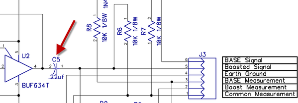
In case anyone isn't familiar... how the DCS decoder works is it computes correlations on the overall 31 bit spreading sequence (see old post for details). I think what we're seeing is the super-imposed 3V sine wave is enough to hurt the correlation level to the point where it's not taking the packet as a successful spread-code match.

Like.... without the legacy carrier you are getting 29-31 / 31 levels of correlation and with the carrier there, it's inflating your noise floor (uncorrelated content) down to maybe 26-27 / 31 where the decoder starts to drop packets.

I think "DCS and Legacy compatibility" assumes the DCS packet is infrequent enough (10 us per second) that the legacy user/system isn't going to notice, and that the legacy voltage is small enough that it won't hurt the DCS correlator. Once the signals have comparable amplitudes (say factors of 3-4) the assumptions start to break down and the two systems interfere. DCS will always be the loser since legacy is continuous wave and it is not. We can probably work out the equations for detection probability of a 31 bit sequence with a sine interferer at a specific frequency. (usually its AWGN noise you do this for).

In the above situation it seems it's only killing them for long exchanges (adding engines, making them active, ...) not the short exchanges like whistles and speed. So in the in-term I suggested they just put a disruption momentary switch that disconnects the legacy base while they add engine. Essentially you hold the button down (open circuit) while the engine is being added. Their legacy performance is solid so I don't really want to attenuate the carrier since that might make new problems for them.


My thinking:

Maybe we could come up with a circuit that detects the rising edges of the DCS packet and temporary disconnects the legacy base (on microsecond scales) to let the DCS signal propagate without the noise floor inflation. It would have to be lightening fast. The DCS bit time is about 260ns (1/3.85 MHz) so probably too fast for a micro-controller.

Quick ideas:

ANALOG: Maybe something analog like a self-resetting latch with an RC delay.  So you have the SR latch with the S port set at a threshold above the legacy carrier but below the DCS excursion. When set it disconnects the legacy base. The R port is an RC network from Q with maybe a 10us (1 DCS packet long) delay before the latch is reset and the legacy restored. If you get successive packets it keeps firing S. You can put a transistor to flush the RC everytime S=1.


DIGITAL: Maybe a cheap FPGA clocked at 200-300 MHz, and just oversampling the waveform heavily. Set an input pin threshold so it's above the carrier, below the DCS excursion and just sample it every clock. If you see a "1" you open a pass-transistor on the legacy carrier. You have a clock counter with a termination value of maybe 100 counts. If you see another "1" on any clock you put the counter back to 0 and keep counting...

Thoughts?

Attachments

Images (2)
  • pic_208_5: Legacy off
  • pic_208_6: Legacy On
Last edited by Adrian!
Original Post

Replies sorted oldest to newest

PLCProf posted:

I dunno-

Your scope images show the composite track signal, I would assume (hope) that the DCS receiver/decoder has some frequency selectivity; the 455 kHz legacy signal is 4 octaves away! If the 455 kHz is getting through to the DCS decoder I can see the problem!


When you look at the spread code MTH uses:  101100000110011010111101000110001, there's sections of 4&5 repeated symbols so you need to support bandwidth down to like 1/5 to 1/6 the bit rate to get clean eye windows, that's a pass-band starting at around 500-600 KHz. It's not a digital FIR filter so the stop-band rejection down at 450 KHz isn't going to be so great. I guess that's why it does come inside.

gunrunnerjohn posted:

I wonder if a notch filter might help there, but it might need to actually be in the locomotive, probably a bit complicated.

FWIW, we've also noticed that at times the Legacy affects the DCS on the club layout.

Yup. It has to go in the engine. That's why it's hard to fix in a club with 100+ members.

Some more quick testing to take a closer look at this. I blew the dust off the old FPGA decoder in the (old post) from last year and made the following setup:

packet_corrlation

So what we have is the FPGA decoder talking with the TIU exchanging packets and reporting the value of Cx (the packet correlation result) back to the PC. Then we have a signal generator injecting a 450 KHz tone with varying amplitude to see the correlation result Cx at different amplitude levels. Obviously doing only 1 packet is statistically meaningless so we compute the average Cx over 1000 exchanges at each voltage level. I've scaled the plot out of 16 instead of 31 (since 0 is actually 100% correlated but inverted) so the single axis can represent best to worst. This is with the actual MTH spreading code (obviously since I am talking to a real TIU)

packet_corrlation2

I don't have control over the DCS excursion voltage since its set by the TIU and not adjustable but I did track it with the scope during the measurement (fixed at 6.17V in the test setup). As you can see from the above, once the injected 450 KHz tone gets to about 1.6V which is (about 25% (1.6 / 6.17) of the voltage of the DCS signal, the decoder correlation starts to drop off rapidly. I'm not sure if this scales linearly or not (like if we normalize the injection to DCS voltage will the drop at the same % each time).

It certainly doesn't fall apart gracefully, 1.2 to 1.8V (about a 0.6V change in injection) pretty much wipes out the correlator in my decoder. I'm sure the MTH one on the PS2/3 is pretty similar, at least according to their documentation.

I think the correlation confidence threshold Ct for MTH is somewhere around 13-14.

Attachments

Images (2)
  • packet_corrlation
  • packet_corrlation2
Last edited by Adrian!

Adrian, I wanted to thank you for spending the evening at the SD3R layout last night. A lot of the DCS users (me included) were going to leave the club over problems running DCS there. Finally, someone with real test equipment and an expert technical understanding DCS put the setup through a real diagnostic session.  The issues you discovered and that trick DCS panel you built gives SD3R's DCS users a light at the end of the tunnel--and I hope the light is an oncoming train...in O Gauge running DCS, that is. Thanks again!  

DJ's Trains posted:

Adrian, I wanted to thank you for spending the evening at the SD3R layout last night. A lot of the DCS users (me included) were going to leave the club over problems running DCS there. Finally, someone with real test equipment and an expert technical understanding DCS put the setup through a real diagnostic session.  The issues you discovered and that trick DCS panel you built gives SD3R's DCS users a light at the end of the tunnel--and I hope the light is an oncoming train...in O Gauge running DCS, that is. Thanks again!  

Thanks! I'm glad to help!

Immediately, I'm thinking it's probably best if you guys put in the Rev "M" TIU, get rid of the bulbs and other things that don't make sense on the track and just see how it works for a few weeks. Then I'll come back (probably mid June) and make sure the new TIU isn't degrading by repeating all the measurements we did last night. In parallel, I've got 2 or 3 ideas on new things we could build to manage the legacy interference (see above) that I'll be trying out prototypes for in our AGHR club the next few weeks or so...

After mid June I'll be a lot more free and I'm willing to come down to SD from LA as much as is needed to get your DCS running well. If there's more issues beyond what we already found, we'll figure it out together and share them with the community here!

Okay I have an interesting thought but I actually don't know that much about legacy and could use advice from someone like GRJ or someone else with legacy expertise... I actually only have DCS trains myself.

Thought Exercise:

I'm thinking the DCS packets are typically about 1.2 to 2.5ms in duration, and if a packet fails or gets a partial match, the TIU or PS2/3 will retry the exchange. If we just took a 555 timer and chopped a 6ms window into the legacy signal say every 25 ms the DCS should be able to find the holes through the retry process, and communicate in them provided they are wide enough, and frequent enough.

Something like this:

legacy_timer


What would this do to the legacy signal?

1. Would it notice the windows (I would expect not since the current DCS packets themselves don't disrupt it).

2. I'm struggling to find good information about the Legacy signal format (modulation, duration, framing, error checking). If the command duration is longer than the window spacing (25ms) legacy will obviously fail. Is there a pulse width and duration that could satisfy both systems?

This may be a simple $4 fix...

Thoughts?

Attachments

Images (1)
  • legacy_timer
gunrunnerjohn posted:
Adrian! posted:
Immediately, I'm thinking it's probably best if you guys put in the Rev "M" TIU, get rid of the bulbs and other things that don't make sense on the track and just see how it works for a few weeks.

Rev "M" TIU?  What's that?

Rev "M" (with quotes) is the TIU with the 1n4148s inside and TVS. The one in my other post. I put one together for the SD3R club.

GGG posted:

So just to be clear, nothing but MTH engines on layout with legacy active and MTH engines can not add?  Any other operator see this?  Lots of layouts run legacy and DCs so why just San Diego club.


I'm one of the DCS operators having to deal with this problem at SD3R.

"[N]othing but MTH engines on layout with legacy active and MTH engines can not add?"  Correct. And the same problem occurs with Legacy engines on the layout also. If no one is running Legacy the next time I'm operating trains down there, I'll do some experimenting with the issues I've been having with the Legacy transmitter base off and on.

Last edited by DJ's Trains
rtr12 posted:

GRJ, it sure does! Do you think any of Dale M's findings would help with this? Or is Adrian already aware of that info? I know you and PLCProf are and I know Dale was boosting the Legacy signal which seems to be somewhat opposite of this?  Just a thought here. It's all over my head...but I try to follow along anyway. 

I think basically from the above measurements.... it's like:

IF) the Legacy signal is strong enough to run the layout at every spot on the track

AND IF) the DCS voltage at the same spot is greater than 4 times the legacy voltage,

THEN: it runs together seamlessly.

ELSE:  Trouble

Adrian,

Thanks again for the DCS module!  I installed it on our layout last night (Monday night).  I didn't have a DCS engine with me to test it out last night, but I called down this morning and they said that they were able to find a DCS engine without a problem with the Legacy signal still turned on.  The difference is that they added the engine on a section of track on the main line near the back door.  The section that we were having problems with were the passing sidings on the Black Line.  We suspect that there still may be "track lamps" under that section that we couldn't get to Sunday night.  Maybe they caused enough problem in that section, combined with the Legacy signal, to block DCS in that section.

I will know more info when they finish their run today.  I'm sure there will be more posts tonight from the guys who ran.


Roger L. posted:

Adrian,

Thanks again for the DCS module!  I installed it on our layout last night (Monday night).  I didn't have a DCS engine with me to test it out last night, but I called down this morning and they said that they were able to find a DCS engine without a problem with the Legacy signal still turned on.  The difference is that they added the engine on a section of track on the main line near the back door.  The section that we were having problems with were the passing sidings on the Black Line.  We suspect that there still may be "track lamps" under that section that we couldn't get to Sunday night.  Maybe they caused enough problem in that section, combined with the Legacy signal, to block DCS in that section.

I will know more info when they finish their run today.  I'm sure there will be more posts tonight from the guys who ran.

Hey there!

Wow you got all 4 channels hooked up already? That's pretty fast! I assume you are using the PH180 bricks as your source to the panel?

As long as you're getting rid of the lamps, do make sure you get rid of the wire and sockets that go with them. Any added capacitance to the track can hurt. I would go loop by loop and make sure literally nothing is connected to the track except the TIU. The smaller the electrical load it drives, the better the situation will be.

I'm working on other possibilities of digitally cutting some holes in the legacy signal for the DCS to talk through, but I'll need to test it in my club a bit and see if it causes undesired problems or not. As I said above I'm going to let you guys try it out a bit then come back in mid-june to remeasure everything and see the TIU "m" is holding up properly.

Once the summer starts and I'm not teaching I can come back as often as needed to get your DCS setup working perfectly.

Yes, I took your board home and spent the day (Monday) prepping some wires.  Then I went down at 5:15pm after the museum closed to install the board.  It still took me about five hours to install it because I had to connect a lot of wires.  Also, I had to mount the board with a hinge so that we could get to the electronics behind it. 

The power connected to the board is still switchable between the Z4000 and the bricks, but members of our club pretty much know to use the bricks for DCS (and TMCC).

I may not have a chance to go to the layout until Thursday to see if I can remove the "track lamps".   There is a lot of stuff in the way.

Showed up Tuesday morning (5-29) for my regular run day.  The new board was installed per above.  We cleaned track like normal and began setting up for our running.  Two members brought MTH engines.  One MTH engine has not been in command mode for over 5 years.  We set this engine up (ps2) on the top black line near the rear exit door, and with their passenger cars fully lighted (non led) they pushed the find engine button on the remote,  within 10 seconds the engine was found and loaded into the remote.  They pushed start and it started. 

The second MTH engine (ps3) was not placed on until later in the day on the lower level green line, with the same results.   Only this time a legacy engine was in operation, a conventional engine was operation and the first MTH with all those lighted cars were in operation.  We have never been able to add an MTH engine when other engines were operating.

Just for drill while the both MTH engines above were operating and the legacy engine was in operation, I got out my rail-king evo ps3 placed it on the blue track near mell's diner and got "out of range".  But the remote loaded the other two engines.  I then moved the evo to behind the roundhouse on the blue line and the evo loaded in seconds, and ran all over the layout.  I was not willing to unplug the legacy system while a legacy engine was in operation.


during the day we have removed what we believed are 100 percent of the bulbs and the bulb holders. 

The only other thing we need to do is remove the loose ground wires.

I believe we are 100 percent better with our MTH set up.

Of course we must get the members who have had issues to come and run their MTH engines and report any issues they have.

Members who have issues must report what issues they have and not just state "my engine does not work"...

We need members to report what issues they have like "out of range", "no engine on track", "engine not found" and the location that they have these issues plus any other thing the remote tells you so we can address these issues.  

We are working on a check list to report issues and hope to have this check list available soon.


bigdodgetrain posted:

Showed up Tuesday morning (5-29) for my regular run day.  The new board was installed per above.  We cleaned track like normal and began setting up for our running.  Two members brought MTH engines.  One MTH engine has not been in command mode for over 5 years.  We set this engine up (ps2) on the top black line near the rear exit door, and with their passenger cars fully lighted (non led) they pushed the find engine button on the remote,  within 10 seconds the engine was found and loaded into the remote.  They pushed start and it started. 

The second MTH engine (ps3) was not placed on until later in the day on the lower level green line, with the same results.   Only this time a legacy engine was in operation, a conventional engine was operation and the first MTH with all those lighted cars were in operation.  We have never been able to add an MTH engine when other engines were operating.

Just for drill while the both MTH engines above were operating and the legacy engine was in operation, I got out my rail-king evo ps3 placed it on the blue track near mell's diner and got "out of range".  But the remote loaded the other two engines.  I then moved the evo to behind the roundhouse on the blue line and the evo loaded in seconds, and ran all over the layout.  I was not willing to unplug the legacy system while a legacy engine was in operation.


during the day we have removed what we believed are 100 percent of the bulbs and the bulb holders. 

The only other thing we need to do is remove the loose ground wires.

I believe we are 100 percent better with our MTH set up.

Of course we must get the members who have had issues to come and run their MTH engines and report any issues they have.

Members who have issues must report what issues they have and not just state "my engine does not work"...

We need members to report what issues they have like "out of range", "no engine on track", "engine not found" and the location that they have these issues plus any other thing the remote tells you so we can address these issues.  

We are working on a check list to report issues and hope to have this check list available soon.


This is good news!

Your club already had a nice antenna in the ceiling but the connector is different (BNC) than the one on the TIU I gave you (SMA) so we couldn't hook it up yet and you're stuck with the short whip antenna I made out of a coax cable. The RF out of range will probably go away if you go back to the good antenna. I will order the SMA-to-BNC adapter and send it to you guys this week. Once you have good DCS in most places, we can use the telemetry train to look at the remaining bad spots and try to figure out why they are bad.

Adrian! posted:
bigdodgetrain posted:

Showed up Tuesday morning (5-29) for my regular run day.  The new board was installed per above.  We cleaned track like normal and began setting up for our running.  Two members brought MTH engines.  One MTH engine has not been in command mode for over 5 years.  We set this engine up (ps2) on the top black line near the rear exit door, and with their passenger cars fully lighted (non led) they pushed the find engine button on the remote,  within 10 seconds the engine was found and loaded into the remote.  They pushed start and it started. 

The second MTH engine (ps3) was not placed on until later in the day on the lower level green line, with the same results.   Only this time a legacy engine was in operation, a conventional engine was operation and the first MTH with all those lighted cars were in operation.  We have never been able to add an MTH engine when other engines were operating.

Just for drill while the both MTH engines above were operating and the legacy engine was in operation, I got out my rail-king evo ps3 placed it on the blue track near mell's diner and got "out of range".  But the remote loaded the other two engines.  I then moved the evo to behind the roundhouse on the blue line and the evo loaded in seconds, and ran all over the layout.  I was not willing to unplug the legacy system while a legacy engine was in operation.


during the day we have removed what we believed are 100 percent of the bulbs and the bulb holders. 

The only other thing we need to do is remove the loose ground wires.

I believe we are 100 percent better with our MTH set up.

Of course we must get the members who have had issues to come and run their MTH engines and report any issues they have.

Members who have issues must report what issues they have and not just state "my engine does not work"...

We need members to report what issues they have like "out of range", "no engine on track", "engine not found" and the location that they have these issues plus any other thing the remote tells you so we can address these issues.  

We are working on a check list to report issues and hope to have this check list available soon.


This is good news!

Your club already had a nice antenna in the ceiling but the connector is different (BNC) than the one on the TIU I gave you (SMA) so we couldn't hook it up yet and you're stuck with the short whip antenna I made out of a coax cable. The RF out of range will probably go away if you go back to the good antenna. I will order the SMA-to-BNC adapter and send it to you guys this week. Once you have good DCS in most places, we can use the telemetry train to look at the remaining bad spots and try to figure out why they are bad.

Adrian, SD3R

This is a great discussion, which I am hopping will address some of the DCS issues we are having at the NJ-Hi Railers club.  I will be at the club on Wednesday and will take track measurements of the TMCC & DCS signals and will disconnect the TMCC signal and see if it is easier to add/control a DCS engine. 

But in the mean time, I have some questions:

 Adrian –

-Can you provide some details on the DCS module which is mentioned above (is it a device that disconnects the TMCC “U” terminal from the track?). 

-You mentioned a DCS telemetry train, please tell me more about this device.        


 SD3R – Can you tell me more about your external DCS antenna system.

 Thanks,

Bob D


rad400 posted:
Adrian! posted:
bigdodgetrain posted:

Showed up Tuesday morning (5-29) for my regular run day.  The new board was installed per above.  We cleaned track like normal and began setting up for our running.  Two members brought MTH engines.  One MTH engine has not been in command mode for over 5 years.  We set this engine up (ps2) on the top black line near the rear exit door, and with their passenger cars fully lighted (non led) they pushed the find engine button on the remote,  within 10 seconds the engine was found and loaded into the remote.  They pushed start and it started. 

The second MTH engine (ps3) was not placed on until later in the day on the lower level green line, with the same results.   Only this time a legacy engine was in operation, a conventional engine was operation and the first MTH with all those lighted cars were in operation.  We have never been able to add an MTH engine when other engines were operating.

Just for drill while the both MTH engines above were operating and the legacy engine was in operation, I got out my rail-king evo ps3 placed it on the blue track near mell's diner and got "out of range".  But the remote loaded the other two engines.  I then moved the evo to behind the roundhouse on the blue line and the evo loaded in seconds, and ran all over the layout.  I was not willing to unplug the legacy system while a legacy engine was in operation.


during the day we have removed what we believed are 100 percent of the bulbs and the bulb holders. 

The only other thing we need to do is remove the loose ground wires.

I believe we are 100 percent better with our MTH set up.

Of course we must get the members who have had issues to come and run their MTH engines and report any issues they have.

Members who have issues must report what issues they have and not just state "my engine does not work"...

We need members to report what issues they have like "out of range", "no engine on track", "engine not found" and the location that they have these issues plus any other thing the remote tells you so we can address these issues.  

We are working on a check list to report issues and hope to have this check list available soon.


This is good news!

Your club already had a nice antenna in the ceiling but the connector is different (BNC) than the one on the TIU I gave you (SMA) so we couldn't hook it up yet and you're stuck with the short whip antenna I made out of a coax cable. The RF out of range will probably go away if you go back to the good antenna. I will order the SMA-to-BNC adapter and send it to you guys this week. Once you have good DCS in most places, we can use the telemetry train to look at the remaining bad spots and try to figure out why they are bad.

Adrian, SD3R

This is a great discussion, which I am hopping will address some of the DCS issues we are having at the NJ-Hi Railers club.  I will be at the club on Wednesday and will take track measurements of the TMCC & DCS signals and will disconnect the TMCC signal and see if it is easier to add/control a DCS engine. 

But in the mean time, I have some questions:

 Adrian –

-Can you provide some details on the DCS module which is mentioned above (is it a device that disconnects the TMCC “U” terminal from the track?). 

-You mentioned a DCS telemetry train, please tell me more about this device.        


 SD3R – Can you tell me more about your external DCS antenna system.

 Thanks,

Bob D


Hey there,

This lionel/DCS module is still being worked out so I haven't decided exactly how it should work yet. Part of me wants to go low tech and simple and just chop windows into the carrier for the DCS to pass through. That seems like it could come with new problems, so having it triggered is probably better. I'm thinking to use a pass transistor so it would adjust the signal voltage of the legacy signal. We could have an "1" voltage and "0" voltage for the two switch states. I think turning it all the way off (disconnecting it) is probably not necessary. I'm prototyping on my ARTY7 FPGA but still waiting on some test PCB layouts I drew up to arrive.

The DCS telemetry train is one of my older projects though it's constantly evolving. In the 5th generation we have now, I have a raspberry pi3 host bolted onto a flat car and one of those 4th order RC filters going to the pickups. I have a home-made scope (fast 12b A/D chip and a FIFO) triggering off the DCS waveforms, and then reporting the DCS excursion voltage to an LCD screen glued on top. Basically like an oscilloscope built into a train with a DCS matched filter already inside.

The SD3R basically did what our AGHR club did too. You lift the sad antenna (stick of wire) off the RF board, solder a coax to the same terminal (and solder the shield to the ground on the RF board). Then you goto a bulkhead (they use BNC we use SMA) and just buy a 900 MHz antenna on Amazon. I also did the same thing on my remote. It makes a big difference in terms of reception. Some discussion of the RF engineering basis is here. 

What kind of DCS issues are you having?


Adrian

The Lionel/DCS module you mentioned above, is that what you left behind with the SD3R club last week or was it something else?

Would you mind sharing the drawings on the DCS telemetry train.  I would like to build one for the NJ-Hi Railers.  It should make it easier to diagnose DCS signal issues on our 30'X200' layout.  Currently we are starting  to do DCS signal testing with a digital scope the club just picked up, but to have a scope on train wheels, that would make life a lot easier. 

DCS  issues:  At times, hard to load an engine into the hand held/tablet or to start up a DCS engine. We get one of those engine not found messages.  I will do a test on Wednesday to see if engines load easier when TMCC is turned off.  Last I checked the TMCC signal it was in the 5vpp range.  We also lose control of engines at various parts of the layout.

Thanks for your help!

Bob D


rtr12 posted:

GRJ, it sure does! Do you think any of Dale M's findings would help with this? Or is Adrian already aware of that info? I know you and PLCProf are and I know Dale was boosting the Legacy signal which seems to be somewhat opposite of this?  Just a thought here. It's all over my head...but I try to follow along anyway. 

Adrian,

just a lay person following along, but I noticed a difference in your tone generator frequency and what Dale Manquen found to be good Legacy/TMCC signal. That was 455Khz with a 5 volt excursion.

rad400 posted:

Adrian

The Lionel/DCS module you mentioned above, is that what you left behind with the SD3R club last week or was it something else?

Would you mind sharing the drawings on the DCS telemetry train.  I would like to build one for the NJ-Hi Railers.  It should make it easier to diagnose DCS signal issues on our 30'X200' layout.  Currently we are starting  to do DCS signal testing with a digital scope the club just picked up, but to have a scope on train wheels, that would make life a lot easier. 

DCS  issues:  At times, hard to load an engine into the hand held/tablet or to start up a DCS engine. We get one of those engine not found messages.  I will do a test on Wednesday to see if engines load easier when TMCC is turned off.  Last I checked the TMCC signal it was in the 5vpp range.  We also lose control of engines at various parts of the layout.

Thanks for your help!

Bob D


What I left in their club is a panel with the PSX breakers, chokes, and a rev "M" TIU with my diode boards inside.  The lionel/DCS switching thing isn't even finished being designed yet! (I'm thinking maybe getting into it this weekend).

I can share the telemetry train details (maybe on a separate post), but the thing is there's a lot of C++ code that drives it. I'll try to put up a thread about it this week.

Your DCS issues are typical of poor correlation (low DCS excursion or low effective SNR) similar to everyone else. A 5V carrier underneath sounds like too much based on the measurements above. I'm thinking of doing a video tutorial on some of these effects at some point...

gunrunnerjohn posted:
Moonman posted:
just a lay person following along, but I noticed a difference in your tone generator frequency and what Dale Manquen found to be good Legacy/TMCC signal. That was 455Khz with a 5 volt excursion.

That would be before the addition of the TMCC Buffer.

The 5vpp is a loaded reading with the buffer.  Other wise the loaded TMCC signal w/o the buffer is in the 1-2vpp range and TMCC engines runs poorly.  

Adrian! posted:
rad400 posted:

Adrian

The Lionel/DCS module you mentioned above, is that what you left behind with the SD3R club last week or was it something else?

Would you mind sharing the drawings on the DCS telemetry train.  I would like to build one for the NJ-Hi Railers.  It should make it easier to diagnose DCS signal issues on our 30'X200' layout.  Currently we are starting  to do DCS signal testing with a digital scope the club just picked up, but to have a scope on train wheels, that would make life a lot easier. 

DCS  issues:  At times, hard to load an engine into the hand held/tablet or to start up a DCS engine. We get one of those engine not found messages.  I will do a test on Wednesday to see if engines load easier when TMCC is turned off.  Last I checked the TMCC signal it was in the 5vpp range.  We also lose control of engines at various parts of the layout.

Thanks for your help!

Bob D


What I left in their club is a panel with the PSX breakers, chokes, and a rev "M" TIU with my diode boards inside.  The lionel/DCS switching thing isn't even finished being designed yet! (I'm thinking maybe getting into it this weekend).

I can share the telemetry train details (maybe on a separate post), but the thing is there's a lot of C++ code that drives it. I'll try to put up a thread about it this week.

Your DCS issues are typical of poor correlation (low DCS excursion or low effective SNR) similar to everyone else. A 5V carrier underneath sounds like too much based on the measurements above. I'm thinking of doing a video tutorial on some of these effects at some point...

Adrain

I have already installed 20-PSX breakers and TVS on 10 of our Z4000/ZWL transformers.  As for the the TIU diode board upgrade, I am going to hold off for the time being.  In the 6 months that I have been monitoring the DCS output signal, I have not seen any  "0" signal outputs.  I have found some TIU DCS sig readings at 10vpp vs the 17-18vpp from a new TIU out of the box.  These are all no load voltage readings at the TIU output terminals.

Look forward to your post on the DCS telemetry car & Lionel/DCS switching.

Thanks again for all your efforts in trying to get to the bottom of the issues which many of us are having with large layouts.

Bob D 

I made a short summary video explaining the limitations of compatibility between DCS and TMCC/Legacy in terms of signal amplitude constraints. I'm 99% sure this is the issue we we're seeing in the SD3R club a few weeks ago. I also put a brief aside about why simple frequency filtering isn't an effective signal separation strategy with the DCS signal (a spread spectrum signal)


Attachments

Videos (1)
DCS_Legacy

Thanks Adrian! Not sure I completely understand it all, but I do see the problem. Sure hope you can fine a solution, and thank you for all your efforts on the projects you have been tackling around here. I love following along even though I don't understand it all, it's still interesting. 

One day we will all have DCS and TMCC/Legacy systems that work even better than they were designed to work! I was always under the impression that these two systems worked well together. You have made some really interesting discoveries about all this! Please keep up you work it is much appreciated by many here, myself included!!

Last edited by rtr12

When there are condition where a strong TMCC signal causes an issue for the DCS signal being decoded as Adrain discussed above, or any other reason where a weak DCS signal exists,  can a DCS buffer be built to increase the DCS signal?  Something similar to the TMCC buffer but at 3.75 Mhz range.

When a DCS system is in speed mode, you now have one way DCS communication between the TIU and engine.  So now you don't have to worry about the return DCS signal to the TIU.  Putting the DCS system in speed mode you loose track signal, info, and read functions, but increased DCS signal from a DCS buffer can address many poor DCS signal issues as the TMCC buffer is addressing in the TMCC world.

For those of us who play with large & extra large layouts (4,000-6,000sf range), a DCS buffer might be the answer to our DCS issues.

Thoughts, comments?

Thanks,

Bob D

There's no technical reason that a booster for TIU carrier wouldn't be possible, but I do foresee some issues.  First off, the signal is combined with the track voltage internally.  Given that fact, the only way I see it working is in passive mode where you would simply be impressing the boosted signal onto the 60hz power that is applied to the output of the booster.  It is possible to have a two-way device for the DCS signal, but I suspect the complexity would not be small.

gunrunnerjohn posted:

There's no technical reason that a booster for TIU carrier wouldn't be possible, but I do foresee some issues.  First off, the signal is combined with the track voltage internally.  Given that fact, the only way I see it working is in passive mode where you would simply be impressing the boosted signal onto the 60hz power that is applied to the output of the booster.  It is possible to have a two-way device for the DCS signal, but I suspect the complexity would not be small.

It’s not so easy. The 244 is about the only line driver with the slew rate needed and the gain is low so it won’t really amplify a weak signal.

maybe a step up transformer is the way to go since you want to deliver voltage, not power to the track 

Adrian! posted:
gunrunnerjohn posted:

There's no technical reason that a booster for TIU carrier wouldn't be possible, but I do foresee some issues.  First off, the signal is combined with the track voltage internally.  Given that fact, the only way I see it working is in passive mode where you would simply be impressing the boosted signal onto the 60hz power that is applied to the output of the booster.  It is possible to have a two-way device for the DCS signal, but I suspect the complexity would not be small.

It’s not so easy. The 244 is about the only line driver with the slew rate needed and the gain is low so it won’t really amplify a weak signal.

maybe a step up transformer is the way to go since you want to deliver voltage, not power to the track 

Adrain

Would a tuned step up transformer be easier to design than the" lionel/DCS switching device" you were talking about earlier in the post.  The "lionel/DCS switching device" would address the issue when the Lionel signal was to strong for the DCS signal,  but would it address the issue of just poor DCS signal strength on a layout w/o TMCC.  

Would a step up transformer address both issues of strong Lionel signal & poor DCS signal?

rad400 posted:

Adrain

Would a tuned step up transformer be easier to design than the" lionel/DCS switching device" you were talking about earlier in the post.  The "lionel/DCS switching device" would address the issue when the Lionel signal was to strong for the DCS signal,  but would it address the issue of just poor DCS signal strength on a layout w/o TMCC.  

Would a step up transformer address both issues of strong Lionel signal & poor DCS signal?

A transformer opens a whole can of worms related to frequency response to avoid the square wave getting badly distorted. It would need to be a very broadband one. Also you have to reject the 60 Hz power so that makes everything even more complicated. The spreading code has repeats of 4, so the frequency content is down to 3.75/4M (940 KHz) and you also need up to the 3rd harmonic to keep things squareish (12.2 MHz). That's a pretty broadband transformer... over a decade of fractional BW which doesn't seem too reasonable.

As for an active amp, the ACT244 is not an amplifier it's a line driver, so the gain is low. It expects a 5V rail-to-rail square wave in on a high impedance and then it drives that square wave into a low impedance. Since they expect rail-to-rail in they can't amplify a weak signal and make it big again, they can just translate a large voltage from a high impedance to a low one, meaning you can't really use them as a down-stream amplifier.

Opamps are not anywhere near fast enough in terms of slew rate to pass a 3.75 MHz line code with the harmonics needed to keep it square-ish. Microwave amps are tuned so they won't pass all the broadband content. Limiting amps don't have the output drive strength.

For a down-stream module, you'd need to use an RC filter to loose the 60 Hz, go into a limiting amp to restore the TTL levels on a high impedance, then go back into another line driver (like another ACT244 or stack of them) to translate back to low impedance. Then you'd need to come up with some way to make that bidirectional.

Last edited by Adrian!
rad400 posted:

Adrain

Would a tuned step up transformer be easier to design than the" lionel/DCS switching device" you were talking about earlier in the post.  The "lionel/DCS switching device" would address the issue when the Lionel signal was to strong for the DCS signal,  but would it address the issue of just poor DCS signal strength on a layout w/o TMCC.  

Would a step up transformer address both issues of strong Lionel signal & poor DCS signal?

This is correct. Making the DCS signal voltage excursion larger solves the a weak DCS signal and overcomes a tmcc signal inflating the correlator floor. The switching device I'm working on just stops the tmcc signal from being involved. However making the DCS signal larger would be really complicated.

Adrian,

We have a DCS on/off switch for each of our four separate tracks at theSD3R layout.  I am not sure of the effectiveness of this switch since we installed the "rev M" board.  But I was thinking: what if I used this switch to block the TMCC signal for a particular track.  Granted that the TMCC signal "wafts" itself over multiple tracks, but if I block the direct feed to a particular track it may be enough to allow the DCS signal to prevail for that particular track.  Granted that I may have to make some changes in the "common ground" in our layout, but I think this is problematic in several ways anyway.

Roger L. posted:

Adrian,

We have a DCS on/off switch for each of our four separate tracks at theSD3R layout.  I am not sure of the effectiveness of this switch since we installed the "rev M" board.  But I was thinking: what if I used this switch to block the TMCC signal for a particular track.  Granted that the TMCC signal "wafts" itself over multiple tracks, but if I block the direct feed to a particular track it may be enough to allow the DCS signal to prevail for that particular track.  Granted that I may have to make some changes in the "common ground" in our layout, but I think this is problematic in several ways anyway.

This could work!

If you wanted to make it even more effective to stop the track-to-track coupling, you can change to a SPDT switch and have the track on the common post toggle between the TMCC feed and earth ground on the two switch poles. If the outer rails are earth grounded the TMCC shouldn't be able to couple in a meaningful way.

Adrian! posted:
rad400 posted:

Adrain

Would a tuned step up transformer be easier to design than the" lionel/DCS switching device" you were talking about earlier in the post.  The "lionel/DCS switching device" would address the issue when the Lionel signal was to strong for the DCS signal,  but would it address the issue of just poor DCS signal strength on a layout w/o TMCC.  

Would a step up transformer address both issues of strong Lionel signal & poor DCS signal?

This is correct. Making the DCS signal voltage excursion larger solves the a weak DCS signal and overcomes a tmcc signal inflating the correlator floor. The switching device I'm working on just stops the tmcc signal from being involved. However making the DCS signal larger would be really complicated.

Tell me more about this switching device?  One of the principal benefits of the current structure is the ability to run TMCC/Legacy and DCS at the same time on the same tracks.  Are you maintaining this capability with your switching device?

Adrian! posted:
rad400 posted:

Adrain

Would a tuned step up transformer be easier to design than the" lionel/DCS switching device" you were talking about earlier in the post.  The "lionel/DCS switching device" would address the issue when the Lionel signal was to strong for the DCS signal,  but would it address the issue of just poor DCS signal strength on a layout w/o TMCC.  

Would a step up transformer address both issues of strong Lionel signal & poor DCS signal?

This is correct. Making the DCS signal voltage excursion larger solves the a weak DCS signal and overcomes a tmcc signal inflating the correlator floor. The switching device I'm working on just stops the tmcc signal from being involved. However making the DCS signal larger would be really complicated.

Adrain

Thanks for all your efforts in trying to address these DCS issues.  The four threads you are currently running on DCS are great and helps many of us to better understand the technical portion of DCS.  I am very interested to learn more about the DCS/Lionel switching device and try it out at NJ-HI Railers.  

rad400 posted:

Adrain

Thanks for all your efforts in trying to address these DCS issues.  The four threads you are currently running on DCS are great and helps many of us to better understand the technical portion of DCS.  I am very interested to learn more about the DCS/Lionel switching device and try it out at NJ-HI Railers.  

Hey,

Here's the idea of the switching device I'm working on...

The basic idea is to detect the very first instant when a DCS packet appears and turns on a switch that blocks the TMCC/Legacy signal, but only for the very short (millisecond time) while the DCS packet is going through. The TMCC/Legacy system won't notice the short delay since it's like 0.001 seconds per second or so, and the DCS system won't feel the effects of the legacy signal since it isn't present during the packet.

The hard part is detecting the packet quickly enough to turn on the switch. The DCS bit period is about 260ns (3.75 MHz), so you'd want to do the detection and turn on in like a 10th of that time... 26 ns. The only thing that can run that fast is an FPGA which is what I'm using.

Here's a doodle of what I've been testing so far:

SWITCH_DEVICE

Attachments

Images (1)
  • SWITCH_DEVICE
Last edited by Adrian!

How are you detecting the DCS signal in 26ns?  Are you just looking for a fast edge from the track?  Given the fact that you could have multiple TIU channels and multiple TIU's, would you have to do this detection for each output?

BTW, you keep saying 3.75mhz for the DCS signal, but all the stuff I've read on DCS says 3.27mhz.  Where exactly are you getting the 3.75mhz figure?  Just curious what the base carrier frequency actually is.

gunrunnerjohn posted:

How are you detecting the DCS signal in 26ns?  Are you just looking for a fast edge from the track?  Given the fact that you could have multiple TIU channels and multiple TIU's, would you have to do this detection for each output?

BTW, you keep saying 3.75mhz for the DCS signal, but all the stuff I've read on DCS says 3.27mhz.  Where exactly are you getting the 3.75mhz figure?  Just curious what the base carrier frequency actually is.

I'm luckly the SD3R club  I'm working on this for only has 1 TIU so I only need a 4 channel ADC. You're right, I'm triggering off the first rising edge. If I was doing this for my own club it would be epically complicated as I would have to coordinate 20 triggers!

I dunno, in the old post with my FPGA decoder I found 7.50 MHz works best which seems to imply a symbol rate of 3.75 MS/s. I'm sure I didn't read anything, I probably just measured it and copied it.

It looks like you're shorting the TMCC signal directly to earth ground.  That may not be good for the drivers in the TMCC command base, and I'm pretty sure my upcoming TMCC buffer won't be happy that's happening either.  Might I suggest you open the signal at the command base (or buffer output) and short the outside track to earth ground, it'll be less traumatic for the TMCC/Legacy base or buffer.

gunrunnerjohn posted:

It looks like you're shorting the TMCC signal directly to earth ground.  That may not be good for the drivers in the TMCC command base, and I'm pretty sure my upcoming TMCC buffer won't be happy that's happening either.  Might I suggest you open the signal at the command base (or buffer output) and short the outside track to earth ground, it'll be less traumatic for the TMCC/Legacy base or buffer.

You're probably right. The left pull down device can go away I guess. The FETs come in packs of 2 so I was trying to be sophisticated

gunrunnerjohn posted:

How are you detecting the DCS signal in 26ns?  Are you just looking for a fast edge from the track?  Given the fact that you could have multiple TIU channels and multiple TIU's, would you have to do this detection for each output?

BTW, you keep saying 3.75mhz for the DCS signal, but all the stuff I've read on DCS says 3.27mhz.  Where exactly are you getting the 3.75mhz figure?  Just curious what the base carrier frequency actually is.

Okay folks.... While conceptually cute this idea is not going to work because of basic referencing. I got 1/3 of the way done before catching this.

The digital waveform on the TIU is referenced to the Layout ground, but the TMCC signal is referenced to the earth ground. So if you build a digital circuit (microcontroller/FPGA) referenced to the layout ground to grab the TIU waveform, then you won't be able to control a transistor because your DCS bottom is the legacy's top and you can't establish cutoff potential on the switching device.

REF1


If you sense the DCS with reference to earth ground that has to consider the 3.75 MHz signal flowing through the single legacy base wire, the base itself and the building wiring, so it really doesn't look like anything.

REF2

It's time to start looking for fast opto-couplers but 26ns propagation delay seems ridiculous.

Attachments

Images (2)
  • REF1
  • REF2
Last edited by Adrian!
gunrunnerjohn posted:

I don't find any opto couplers with that speed, that's pretty fast.  Here's one that looks possible...

https://www.mouser.com/Product...qLppiUeN9C2DwQ%3d%3d

Okay a new plan has been formulated:

It's going to be the 3 pole RC filter to trigger a resettable monostable multivibrator using a 74HCT123. to trigger the DCS waveform off each TIU output. Then a galvanic isolator to leave the detector part that is referenced to the layout ground and enter the control side referenced to earth ground. So it'll need two isolated 5V supplies, one for each side (5Va and 5Vb).

DCS_SWITCH2

I still need to think about the switching element. I'm on the fence between a simple jfet, and those TI analog mux products. Either way there needs to be bias under the TMCC signal to get the transistor to the operating point. Probably just (R+R)||C.

It's 25ns on the one-shot chip and 15ns on the coupler so we're about 15-20% into the period of the first bit already (266ns). Parts are ordered so I guess I'll breadboard it next week.


Attachments

Images (1)
  • DCS_SWITCH2
Last edited by Adrian!
gunrunnerjohn posted:

I look forward to the results.  I doubt the brief interruption of the TMCC signal should affect TMCC/Legacy, they send multiple copies of commands.

Some slow progress and updates on this. Here's the CMOS variant of that one-shot (CD74HCT123E) chip triggering off a DCS waveform through that RC filter. Good clean edges around the packet and no misfires in the middle. Blue is the output, yellow is input DCS. The initial delay is like 8.5ns end to end, but I still need to propagate this through the idolator and into the switch (about 18ns of margin remaining). I used Cx=10n, Rx = 10K, so that's nominally a 50us box per trigger received.

Overall shape:

pic_243_4

Leading edge behavior:

pic_243_2

Trailing edge behavior:

pic_243_3

Packet procession behavior:

pic_243_1

This detector is the hardest part (I think). The next is to transfer the reference from the layout ground (for DCS) to the earth ground for TMCC using a galvanic isolator, and then developing a graceful switching circuit that doesn't short out the TMCC base. It's going to look weird because it needs two 5V supplies referenced to the different grounds.

So for everyone else following this the idea who may be a little lost....the concept is we're building something that detects when DCS (the yellow waveform) is communicating between the TIU and train, and generating the blue box which will eventually inhibit the TMCC signal. Since the DCS packet is only about 1/500th of a second long the TMCC shouldn't notice the short time it's being inhibited. At the same time the DCS decoder performance improves because there isn't a 450 KHz TMCC signal inflating the apparent noise floor.

Attachments

Images (4)
  • pic_243_2
  • pic_243_3
  • pic_243_4
  • pic_243_1
Last edited by Adrian!

This looks like something that could be incorporated into my upcoming TMCC buffer, kill two birds with one stone.

Speaking of the TMCC Buffer, I was thinking about this issue and the increased amplitude signal from the TMCC buffer. 

The basic idea behind the TMCC Buffer is to provide a lower impedance drive to drive the capacitance of a large layout.  It increases the TMCC signal amplitude and uses a lower impedance driver to accomplish that goal.  Adding this circuitry would allow us to simply cutoff the TMCC signal from the buffer during the DCS packet interval.

gunrunnerjohn posted:

This looks like something that could be incorporated into my upcoming TMCC buffer, kill two birds with one stone.

Speaking of the TMCC Buffer, I was thinking about this issue and the increased amplitude signal from the TMCC buffer. 

The basic idea behind the TMCC Buffer is to provide a lower impedance drive to drive the capacitance of a large layout.  It increases the TMCC signal amplitude and uses a lower impedance driver to accomplish that goal.  Adding this circuitry would allow us to simply cutoff the TMCC signal from the buffer during the DCS packet interval.

So how about this...

1. When I do my board I'll put terminals with the Earth-referenced TTL out.

2. Then on your booster you can have a TTL in port that inhibits the driver.

That way we'll be compatible-ish.

Of course this clever trick will only work with 1 TIU. I think in our club the physical delay (speed of light) between the 5 TIUs is already way more than 25ns.

Hmm...  The whole point of this is mostly for large layouts, that's the only place that the TMCC Buffer makes sense. 

I haven't researched this, but if you have multiple TIU's, don't all the commands go out on all channels?  The TIU doesn't know which segment that the locomotive is, and it could have transitioned to a different place.  I suppose there's enough time for the signal to have skew based on each TIU has to process the incoming remote command individually.

I did have another thought.

The TMCC buffer increases the signal amplitude in an effort to combat the increased capacitance of a large layout.  The output buffer is capable of driving about a .1uf capacitance of the outside track to earth ground.  One of the issues is the amplitude, the buffer has a 3:1 gain.  I wonder if dropping the gain to unity and adding a larger isolation capacitor would allow it to drive the same capacitance but have less effect on the DCS signal?  This TMCC Buffer Schematic.pdf is what we have now.

Attachments

gunrunnerjohn posted:

Hmm...  The whole point of this is mostly for large layouts, that's the only place that the TMCC Buffer makes sense. 

I haven't researched this, but if you have multiple TIU's, don't all the commands go out on all channels?  The TIU doesn't know which segment that the locomotive is, and it could have transitioned to a different place.  I suppose there's enough time for the signal to have skew based on each TIU has to process the incoming remote command individually.

I did have another thought.

The TMCC buffer increases the signal amplitude in an effort to combat the increased capacitance of a large layout.  The output buffer is capable of driving about a .1uf capacitance of the outside track to earth ground.  One of the issues is the amplitude, the buffer has a 3:1 gain.  I wonder if dropping the gain to unity and adding a larger isolation capacitor would allow it to drive the same capacitance but have less effect on the DCS signal?  This TMCC Buffer Schematic.pdf is what we have now.

Inside the TIU there's a mux (U502) which steers the FPGA to each of the each of the 4 channels one by one. Although everything happens together, if you look close you can see different channels (VARx, FIXEDx, ..) are on different time slices.

You could try to do a blanket window over all of them, but now your talking 0.2 seconds and TMCC/Legacy might start to take notice. Also physically... if you have two TIUs and either of them is more than 20 ft away from the TMCC input, that's already a good 23ns of delay right there.

Both DCS and Legacy are voltage-mode receivers so you don't want to lower the gain of that driver or you're directly dropping your SNR on TMCC.


A last one we could also think about (but it's really hard compared to the the switching idea) is to induce a copy of the TMCC signal on the center rail that closely mirrors the one induced on the ground. Nominally the TIU and Transformers are in common mode to the injected legacy signal meaning both + and - outputs of the TIU/transformer are going up and down at 450 KHz wrt the Earth ground and with the same phase and amplitude on center and running rails. Of course practically this is not the case since the capacitance of each side (center and running rails) to Earth ground is a little different and the circuitry inside the transformers and TIU aren't perfectly symmetric. Also it can be different at different locations along the layout due to series R and L of the track and wiring.

If the Legacy signal is very well balanced on both rails, the DCS decoder which senses things differentially should not see it, as it's on both ground and power rails. That's the operating principle of DCS when legacy is present.

So could we build a small circuit/board/module that senses the differential 450 KHz at some points along the track and copies the TMCC onto the center rail with just enough amplitude to balance them.

This would probably be feedback based...

-Have a diff amp across the rails with a high-Q 450 KHz filter in front

-Have some type of envelope detector on the filter to get a DC-ish value from the legacy tone

-Use that envelope DC to control a variable gain stage like your booster connected to the center rail and make them balanced.

This is probably an even better idea than what I'm doing, but it's pretty hard.

Last edited by Adrian!
Adrian! posted:

Here's a doodle of how that might look:

Also you're pretty-much relying on the BPF to keep the DCS transients out of the loop. I doubt it'll be so good when the the inputs are being yanked +/-7V with ns rise and fall times. We could make the loop time constant really really really long (like seconds) so the DCS timescales don't affect where it settles.

Also^2 unlike the outside rail, the center rail is in blocks, so you're going to need a lot of these for a big layout.

Last edited by Adrian!
gunrunnerjohn posted:

One wonders if there's not an easier method.  How about a low-pass filter that simply couples the outside and center track together.  Obviously, it would have to pass the 455khz TMCC signal and block the DCS signal lowest frequency component, that's around 1mhz, right?  With that approach, you could do each DCS block.

Need to block the 60Hz too....

Also it needs to be really low impedance to force the rails together. I looked at ceramic filters but they are all 3dB insertion loss meaning they don’t impose voltage well, plus they need the earth ground to be routed to them... not so easy 

Well, I don't know that we have to block the 60hz, a popular method of insuring that S-gauge has good TMCC reception is to tie the rails together with capacitors to couple the signal, they don't do anything to block the 60hz.

Trying to think outside the box here, since having the capability on every TIU channel to interrupt the TMCC signal seems to be a rather giant task for large layouts.

I'm not so sure that we need the amplitude from the TMCC buffer if we make the signal low enough impedance.  After all the command base manages to work with many pretty large layouts with it's wimpy output circuit.  One of the limitations of how much capacitance the buffer can drive is the 15V PP signal amplitude, it takes a bit of power to push that out.  Cutting that in half would allow a lower impedance drive of the TMCC signal.  Obviously, I haven't tested this, just tossing out ideas.


In thinking about this issue, I'm wondering why the Legacy signal has such a strong effect on the DCS signal.  After all, the Legacy signal is referenced to earth ground.  I'm wondering how the Legacy signal gets the drive to affect the DCS in the fashion illustrated.  Did you do any checking to see if there's something odd about that particular layout configuration?

John,

I'm wondering why the Legacy signal has such a strong effect on the DCS signal.

Good question. I'm wondering if it actually has any real effect at all.

In the past, any time there's been a perceived negative effect of the Legacy signal on the DCS signal, it's typically turned out to be due to one of the following:

  • Faulty earth ground.
  • Faulty command base power supply or AC power strip.
  • Faulty command base.
  • Legacy engines themselves (arguably the most prevalent reason).
  • The problem wasn't due to Legacy at all.
Adrian! posted:


packet_corrlation2

A lot of it is balance since it's two voltage sources stacked on top of each other.

The Legacy 455 KHz is from Earth ground to layout ground and then the DCS voltage is stacked on top from layout ground to layout center. They really rely on the 450 KHz potential being at the same at both outer and center rails, and not any type of frequency selectivity. If both rails are moving up and down together you can reject a good 1-2V, but if not of course the decoder performance falls off.

If you look at the data from before (above), you can consider the amplitude "differential voltage" or imbalance. I'm going to redo this test in balanced mode too so we have data.

Barry, that's precisely what I'd like to find out.  By understanding what Adrian was seeing at the test layout, we may be able to understand why it was happening.  At this point, I'm not saying there is or isn't a problem, only that more than one person has reported similar issues. 

I know even at our club, we've had on and off issues where disconnecting the Legacy would help the DCS, so I think it's important to understand the whys and wherefores.

I would say the SD3R club I'm helping is a special situation. They are a museum open 6 days a week so they can't just tear their layout down and rewire it from the ground. Ideally it would be best to go in and balance the legacy signal to be the same at the ground and center rail at every spot on the layout so it stops inflating the noise floor on the DCS, but it's not going to happen with their operational constraints. So I'm working out this switch board, which is probably overkill for most cases, but suits theirs well.

I'm posting because the forum is for discussing special cases.  We have your book for the usual stuff!

Last edited by OGR CEO-PUBLISHER

Upon reading and following this post I was and still am under the impression that there is a problem with Legacy and DCS. After following for a long time I finally came to the conclusion that 1. There is a problem with a particular clubs layout and that layout only. 2. This issue had scared the igee begees out of me till I realized this is seems to be a electronic techo's in depth view into a problem that I now am thinking it is no where near the size he has made it. 3. Your advice is taken. DONE READING! I do thank you for your RESEARCH but now have concluded it did nothing but scare me. As a NEW Legacy and a 3 yr old on DCS I feel others in my area would feel the same way. The Title in all caps meant to me "Hey here is an important problem so beware and look out for it." Please understand I am not intending in any way to put you down or discredit you. I do agree with Barry that this is more a research issue than a problem for the masses. Thank you for your willingness to pursue the issue for this club and I wish you a speedy repair to the problem as I feel that is the issue, fixing the problem.

Respectively

Curtis

This is not totally "nonsense" as I've seen this very issue at two locations.  While it's generally not a problem, it is a potential problem for some, and a real one for others.  What I'd like to understand in more detail is how this effect is manifested in a real layout.  While injecting the signal on the bench is a very worthwhile exercise, and also a repeatable scenario, I'd like to understand the depth of the issue on real layouts.

As I have stated, I've actually seen this on our club layout, it's not just one layout.  I won't dispute that ours is "poorly wired" as it was initially wired for TMCC/Legacy only, so that could be a significant part of the issue.  What interests me is knowing enough to find out what the root of the problem is.

I find this information all very interesting, even though it's mostly over my head. I do like to learn about these things and other things electronic. It doesn't scare me or make me want to start re-doing my layout, as it all still runs just fine together here. I wired it specifically for DCS per Barry's book which has worked great since the beginning a few years ago. I added Legacy later on and it has worked flawlessly since as well. 

My layout is nowhere near the size of a club layout or many other's layouts that I have seen around here. That could and probably does make a big difference. However, if I ever do have problems this work by the more knowledgeable (than I am) folks here may very well help me (or others) solve that problem someday. Knowledge is a wonderful thing, and so is learning about things, IMO. 

Last edited by rtr12

There is no question that Barry is one of the pioneers in DCS. His DCS companion sits prominently on our table at the AGHR club layout. I have met Barry several times and he has been an incredible source of reference and information. His insight into DCS has helped many of us.

About a year ago, Adrian Tang joined our AGHR club. Adrian, a PhD, NASA and JPL engineer brings the under the hood understanding to DCS. We went through 10 TIU's in less than a year. Adrian discovered a flaw in the REVL. Working  in conjunction with Jason at MTH, they found the fix. New REV L's have the fix. We have had flawless operation and no TIU replacement since November.

These two gentleman are priceless for our hobby. Let's take advantage of them and not get into a pi...ng contest.

Jeff

Okay so let’s revisit the discussion and establish the facts:

  1. Two large layouts (SD3R and AGHR) near me, and apparently two near GRJ experience a situation where disconnecting the legacy base significantly improves DCS performance (responsiveness, delay when adding engines, track signal test numbers). Others may have this too, but we only know of these four right this moment.
  2. DCS is a CDMA packet with a bipolar line code which typically exhibits 13-14V pkpk excursion when everything is working well. This is confirmed to be the case in the two layouts near me, both have >13V of DCS excursion.
  3. Legacy is a continuous wave carrier at 455 KHz and is applied between the layout ground and the earth ground.
  4. The TIU output circuitry (red and black terminals) are after an internal transformer so they are only referenced to each-other, not earth ground. The TIU output network has a low output impedance meaning the Legacy carrier applied to the ground is copied onto the center rail as the TIU output transformer winding is floating with respect to earth ground.
  5. Bench experiments show that the correlator in the DCS decoder architecture can only tolerate about 1.5V of this 455 KHz carrier at the input before the error rate becomes high. This effect is known in communication literature as “correlator noise floor inflation”. The presence of the carrier, in effect, lowers the average number of correlated bits per CDMA packet.
  6. A DCS engine on the layout has no connection to, or knowledge of earth ground, only layout ground and layout positive (the TIU red and black terminals). That means that it can only see the voltage difference between the center and outside rails. Therefore the 455 KHz carrier must be appearing across the center and outside rails, not just between the 3 rails and earth ground, and it must be appearing on the order of 1-2V of amplitude in order to have any effect on the DCS system (based on the bench tests).
  7. The only possible signal voltage scenario that explains this is that the legacy carrier at 455 KHz is not equal on the center and outside rail. This can occur in two possible ways: (iA). There is a path to earth ground at 455 KHz of modest impedance in the layout from either the center rail or outer rails, but not both. In this case the superposition onto the floating TIU is not balanced. (iB). The capacitance to earth ground from the center and capacitance from earth ground to the outside rails differ significantly.
  8. Since the TIU is isolated by the output transformer the only explanation for case (i.a) is through the power source. Both layouts investigated use the PH180s which are isolated transformers so this seems unlikely. Also both layouts investigated have chokes between the track and PH180, so the impedance at 450 KHz must be pretty high. (i.b) Seems more likely and makes sense that it would be exacerbated in a large layout. A small layout will have a small difference in node capacitances, while a large layout will have a larger difference. A large difference in capacitance will create an amplitude difference between the center and outside rails, across the DCS decoder, and inflate the noise floor of the decoder.


Illustrations of nominal, case i.a and i.b voltage behavior:

legacy_cm

To correct the i.a scenario the only option is to change the power source and ensure it's isolated. The chokes seem to do this automatically, but I've confirmed that the PH180 is an isolated power supply. With a multi-meter there is no voltage from either terminal to earth ground. I'm sure others here can confirm this also.


Then the possible solutions to correct a capacitive imbalance between center and outer rails (scenario i.b) are:

  1. Rewire the entire layout making sure the wire load on TIU +/- are coupled tightly and well balanced. Probably the best option for small home layouts, not possible with large museum or club layouts that need continuous operation and that took 10+ years to build in the first place.
  2. Temporarily inhibit the legacy carrier while the DCS packet is present, preventing it from inflating the noise floor in the decoder. This is the design I am working on. This will work well for large layouts with not a lot of TIUs (maybe 1 or 2). This is the SD3R case. The AGHR case is 5 TIUs so it's not a good solution for them becasue as you increase to 4-5 TIUs you have to monitor a lot of channels (20 for 5 TIUs). Further, those TIUs are probably not physically close to each other and still have to coordinate with an inhibiter of some form at the one legacy base meaning a lot of added wiring. The delay is also an issue because you have to inhibit the legacy quickly when the DCS appears. To respond after the first bit the design can tolerate only on the order of 25-50 ns delay.
  3. The last option is to build some type of active circuit to ensure that the 455 KHz carrier is the same voltage for (earth ground to outside rail) and (earth ground to center rail) making it truly invisible to the DCS decoder. Using two of GRJ’s boosters in parallel with some type of feedback connected to control the gain stage may be able to accomplish this.


So unless anyone here has specific objections to anything stated here (and if you do please identify them specifically and lets discuss them... that's what the forum is for!), I suggest we continue with the design work and post the results to inform the rest of the community about the outcomes of the possible solutions above.

~Adrian

Attachments

Images (1)
  • legacy_cm
Last edited by Adrian!

Adriani,

  1. Rewire the entire layout making sure the wire load on TIU +/- are coupled tightly and well balanced. Probably the best option for small home layouts, not possible with large museum or club layouts that need continuous operation and that took 10+ years to build in the first place.

You proved my point. The culprit is the wiring. That's the root cause of the problem.

The fact that turning off the Legacy command base improves things is not the same as proving that the command base causes the problem. Rather, it's the wiring that causes the problem.

Wouldn't you agree?

Last edited by Barry Broskowitz
Barry Broskowitz posted:

Adriani,

  1. Rewire the entire layout making sure the wire load on TIU +/- are coupled tightly and well balanced. Probably the best option for small home layouts, not possible with large museum or club layouts that need continuous operation and that took 10+ years to build in the first place.

You proved my point. The culprit is the wiring. That's the root cause of the problem.

The fact that turning off the Legacy command base improves things is not the same as proving that the command base causes the problem. Rather, it's the wiring that causes the problem.

Wouldn't you agree?

Well I think this is perspective. From a user perspective (someone who only has the DCS/Legacy hardware they have and cannot change it) I would  agree with you, the layout wiring is not tightly enough and therefore not meeting the criteria for coexistence of the two signalling methods (SNR, balance, relative amplitudes) required.

From the designer's perspective (someone who is free to change the hardware to whatever) I would say the current principle of operation for TIU and Legacy to co-exist well makes a lot of assumptions  (SNR, balance, relative amplitudes) and those assumptions impose layout constraints that are too tight for the real-world layouts encountered.

I can't speak to the SD3R club, but the AGHR club re-wired the layout over the last 2 years with your book in hand, and it's a pretty good result. The wires are kept to length, tapped correctly, and run in tight pairs in all places, yet these effects are still there. I think in this case especially, the user has done what can be reasonably expected of them, and it's time to look at the design assumptions.

The imbalance is expected to scale with layout size....if you think about it physically, the 3 rail track has 1 center rail and 2 outside rails, so the design assumption that both capacitances are identical is already not a great one to make since there's literally twice the surface area on one node relative to the other. So the difference in cap developed will be like K(2Crail - Crail) where Crail is the capacitance of one rail, and K is some layout scaling factor. Second, the outside rails are one node and the center rail is another so the fringing effect will lead to the capacitance favored on the outer rails, especially where the track passes things connected to earth ground. From a design perspective I would say these layouts are exceeding the design envelope of the TMCC/Legacy compatibly principle. That is why we are here talking about design solutions.

Please, let's listen to Alan and simply discuss the issue rationally.  There's room for dissenting opinions, nobody here knows it all.

I don't think there's a lot of disagreement that the specific wiring of a layout quite possibly had a significant effect on this problem.  Our mission, if we choose to accept it, is to figure out how to solve this with a minimum of impact to the overall wiring.  I can tell you for sure that the larger layouts i see are not going to do a massive rewiring job, so that option isn't really on the table.  Only by really understanding why the interference exists can we hope to create a way to minimize it.

Adriani,

Let me share something with that, while not exactly on point, may provide some food for thought.

A few months ago, I installed a DCS Explorer on my son's and granddaughters' small 4X8 layout. It's 2 loops of RealTrax, with 4 RealTrax switches that provide a pair of crossovers between the loops. The switches use track power. Each has a lantern and a lighted controller. The layout is powered by a Z500 brick into the DCS Explorer, and then on to the tracks via a pair of lockons.

At all times, there are two trains sitting on the tracks, a Rail King diesel with 3 postwar Lionel illuminated passenger cars and a Rail King steamer with a lighted caboose. In addition, there's an illuminated accessory that works off track power that turns on with the layout.

The Lionel passenger cars are a new arrival and their addition seems to have caused the situation that I'm about to describe. I worked the following over the phone (Allan and the girls are 1,100 miles away).

My son and his two little girls use the DCS App on his iPhone and their Kindle Fire tablets. For some reason, my son recently reset the DCS App on all 3 devices, causing the two engines to be deleted from the app. When he attempted to re-add the engines, the following scenario evolved:

  • The DCS Explorer was powered up in MTH mode and the DCS App connected to the network generated by the DCS Explorer.
  • The DCS App was launched and a Refresh command was issued. The DCS App reported "No DCS Explorers found", although, as expected, track power was turned on and a watchdog signal was broadcast. Both engines remained dark and silent.
  • My son shut down the DCS Explorer, reset the DCS App, reset the explorer and toggled the Home/MTH mode switch a few times. We then reattempted to get things to work.
  • We were able to then get the DCS App to recognize and connect to the DCS Explorer about 90% of the time. However, when it did, it still reported "No engines to add".

What finally worked was the following:

  • We physically disconnected the tracks from the DCS Explorer.
  • We restarted the DCS Explorer and connected to its MTH mode WiFi network.
  • We launched the DCS App and issued a Refresh command, The DCS App found the DCS Explorer.
  • We reconnected the track and the layout powered up. Since the DCS Explorer only issues a watchdog signal at the time of the initial Refresh command, as expected both engines came up in conventional mode, bright and noisy.
  • We added both to the DCS App without any issues whatsoever.

This workaround was 100% successfully repeatable. The permanent solution will be to replace the Z500 with a Z1000 for track power, and use the Z1000's accessory power for switch tracks and accessories.

I spoke with an EE friend (and well-known forum member) who is arguably the most knowledgeable person around as regards DCS hardware and protocols. I asked if an overcurrent demand could cause the DCS Explorer to behave in the described manner and allow the workaround solution that we implemented. He agreed that the overcurrent demand was more than likely the culprit.

While the layout at the club is in no way similar to my son's layout, perhaps you may see some small aspect of the issue that relates to your current (pun intended) club layout's issue.

As an aside, I've had my son install his old DCS Remote Commander receiver in passive mode to generate a watchdog signal whenever track power is removed and restored, along with an inline track power switch.

Barry, while this is an interesting situation, I can't see that it really addresses anything we're looking at here.  We're dealing with the full TIU and Legacy, and I'm pretty sure neither of the layouts I see this issue on are underpowered.  You're dealing with the DCS Explorer, which I don't know that most of us even have experience with at this point. 

Not sure this has much bearing on the issue here.  Of course, once we nail down what the issue really is, that opinion could change.

OK.... I really don't wish to enter into this....

1) I can't run TMCC on my 2 rail layout without losing control of my DCS engines. I tried several recommended fixes and now I have to isolate TMCC to it's own layout. I never found a satisfactory solution.

 2) I have encountered difficulties with DCS signal when the power or current drawn reaches the limits available. Whether it's from too many engines receiving power in a single block, or even drawing down a Z500 or Z1000 brick. That's just one issue over the many spread over years of use. 

 I have also found that isolating the negative (or return) into blocks on my G scale DC layout helped with signal and control with large lash-ups. I was told that would not help but it did. Signal was fine with single engines but control suffered with several. It appeared when I upgraded to an older version of DCS and I never pinned down why it happened.

 I don't have that issue with my O scale AC powered layout, but it maybe something to try if you get decent signal level but can't get large lash-ups to respond correctly. I imagine that would be difficult to do with many users having a buss type common return.

 The best thing I have ever tried when encountering trouble adding engines was to have a dedicated TIU#1, and a remote with no other TIU's listed. Yet that seemed to fail later on with more upgraded DCS versions.

 3) I can't stand reading fellow users attacking each other over solutions that they come up with. I don't care what works for you and what should not if you are just going to hammer each other until surrender. Knock it off. Tell me that the return on my large DC layout doesn't need to be blocked and I'll tell you it does. Pull out a scope, read me the DCS patent, etc., I don't care.

 I have spoken with many users who don't like the moderation here, and or don't like the people who regularly devote their time to help here and maybe seemingly stubborn to new ideas at first. I will leave as I don't need any crap anymore. I have left several other forums as well.

Barry you are a very intelligent man and I respect you deeply but you seemed to attack this subject like there's no issue and I have seen them myself. You maybe right about the subject. You just may need to allow things to die off on their own.

Adrian, you also seem like an intelligent man and I respect your attempts at understanding why the system fails sometimes. Working with several very intelligent people in my past has helped me to look at issues and other people with better understanding. You have to realize you are opening some cans of worms from the past attacks from other brand loyalists. They want nothing other than to drive MTH to defeat. They have attacked me, my computers, and my choices of brands in the past. It's sad but true. I laugh now. It was ridiculous.

 So you 2 are dividing the posters here and will undoubtedly cause grief and flame the fires. I have blocked many posters here in the past. I try not to as I can learn from even the worse. I unblocked GRJ for example, when he settled down from his seemingly attack on MTH years back. If he meant to or not, he came across as an enemy of MTH and me, as that's all I ran. He advised a user to rip out the PS2 guts as TMCC was a better choice. I as a MTH fan obviously don't agree with that, but that's his opinion. I think TMCC was way ahead of it's time and yet got passed by with technological advances, being stuck in the mud. So I still read his posts and learn from his help, yet disagree fundamentally with his choices.

 Maybe you 2 will stay friendly and I hope you do. You both need to watch how you present your opinions. You are creating enemies whether you want to or not.

 PS. my layout is one of the ones affected by TMCC when it's plugged in. I knew it years ago. I isolated it until I once again rewired and did not realize the grounds were connected and the gremlin reappeared.

Last edited by Engineer-Joe
Engineer-Joe posted:

OK.... I really don't wish to enter into this....

1) I can't run TMCC on my 2 rail layout without losing control of my DCS engines. I tried several recommended fixes and now I have to isolate TMCC to it's own layout. I never found a satisfactory solution.

 2) I have encountered difficulties with DCS signal when the power or current drawn reaches the limits available. Whether it's from too many engines receiving power in a single block, or even drawing down a Z500 or Z1000 brick. That's just one issue over the many spread over years of use. 

 I have also found that isolating the negative (or return) into blocks on my G scale DC layout helped with signal and control with large lash-ups. I was told that would not help but it did. Signal was fine with single engines but control suffered with several. It appeared when I upgraded to an older version of DCS and I never pinned down why it happened.

 I don't have that issue with my O scale AC powered layout, but it maybe something to try if you get decent signal level but can't get large lash-ups to respond correctly. I imagine that would be difficult to do with many users having a buss type common return.

 The best thing I have ever tried when encountering trouble adding engines was to have a dedicated TIU#1, and a remote with no other TIU's listed. Yet that seemed to fail later on with more upgraded DCS versions.

 3) I can't stand reading fellow users attacking each other over solutions that they come up with. I don't care what works for you and what should not if you are just going to hammer each other until surrender. Knock it off. Tell me that the return on my large DC layout doesn't need to be blocked and I'll tell you it does. Pull out a scope, read me the DCS patent, etc., I don't care.

 I have spoken with many users who don't like the moderation here, and or don't like the people who regularly devote their time to help here and maybe seemingly stubborn to new ideas at first. I will leave as I don't need any crap anymore. I have left several other forums as well.

Barry you are a very intelligent man and I respect you deeply but you seemed to attack this subject like there's no issue and I have seen them myself. You maybe right about the subject. You just may need to allow things to die off on their own.

Adrian, you also seem like an intelligent man and I respect your attempts at understanding why the system fails sometimes. Working with several very intelligent people in my past has helped me to look at issues and other people with better understanding. You have to realize you are opening some cans of worms from the past attacks from other brand loyalists. They want nothing other than to drive MTH to defeat. They have attacked me, my computers, and my choices of brands in the past. It's sad but true. I laugh now. It was ridiculous.

 So you 2 are dividing the posters here and will undoubtedly cause grief and flame the fires. I have blocked many posters here in the past. I try not to as I can learn from even the worse. I unblocked GRJ for example, when he settled down from his seemingly attack on MTH years back. If he meant to or not, he came across as an enemy of MTH and me, as that's all I ran. He advised a user to rip out the PS2 guts as TMCC was a better choice. I as a MTH fan obviously don't agree with that, but that's his opinion. I think TMCC was way ahead of it's time and yet got passed by with technological advances, being stuck in the mud. So I still read his posts and learn from his help, yet disagree fundamentally with his choices.

 Maybe you 2 will stay friendly and I hope you do. You both need to watch how you present your opinions. You are creating enemies whether you want to or not.

I don't know any history since I'm new here (late 2016) and I'm not interested in subscribing to that. I just report the findings as they are observed, provide designer's insight into them for those who are interested, and post them for discussion (which is the purpose of the forum). Sometimes I'm discussing issues observed (like this post), and sometimes I'm discussing new ideas that aren't about issues or problems. As a circuit designer DCS to me is a CDMA data link that has a plastic shell on top that happens to look like a train. Similarly a Lionel train is an MF receiver with a similar plastic shell on top (yeah, I had to look up the name of the band for 450KHz... it's not common). There are plenty of examples of each operating well, and examples of each operating poorly. I don't see how this reflects to a particular brand. What keeps me excited in the hobby is the circuit fundamentals and new ideas to make improvements, even incremental ones. As in my journal article writing and book writing, I keep my posts to the technical facts and encourage others to validate claims for themselves (good technical practice). Honestly, I'm not sure how this thread got so personally involved. Let's just stick to facts and good technical dialog.

Anyways, I have an interesting idea for this I was about to post anyways...

Next time I have a chance  I want to measure the capacitance with one of those fancier DMMs that have that function between the center rail and earth ground and the outside rail and earth ground, both for a normal layout and a layout where this condition is appearing. I'm still debating if the TIU should or should-not be connected during the measurement.  I think the right answer is yes. If we see a big difference in capacitance numbers, maybe the simplest answer is to add cap to earth ground on the smaller one to balance it with the bigger one. Should be an enlightening experiment into this condition.

Last edited by Adrian!

just a few reasons why I would like to further your efforts Adrian, and I do find the attempt to be worth the effort.

The magic bulb idea when first suggested was bashed by MTH techs as unnecessary. It did get accepted later on. It did help older TIUs.

 Susan's filter idea was scoffed by some posters and members here at first mention, http://www.slsprr.net/technical/filter.htm

until they finally recognized it's benefits were real and mattered. Most older users of DCS had a ton of bulbs around the layouts so what's a few more? So some still don't see any benefit.

 Both of these "cures" became unnecessary with the release of the newer version L TIUs.

 Barry's rules came after some attempts by various posters  here to correct poor results on some layouts. (Posters gathered around Barry as a source of what to do and how to do it.) Other posters left. Some in frustration over lack of public respect for their efforts.

They were all accepted rather than spending the energy to refute them. Then came "the book" on DCS. It became accepted that the rule about all cable lengths should be close in length, was wrong. So centrally locating the TIU was ignored. A lot of users have buss wired layouts that the DCS signal works well on. It was suggested to just try it first and see what results you get. Having the basics in print helps many get started correctly in the right direction.

 There have been various bugs in the DCS software that aren't really made public as the bashers blew the bugs out of proportion.

"I dropped my engine into a pool and ran the layout on 3 phase 440. The engine fried so it must be from the software bug!" " You owe me a new engine MTH!"

  So you may not mean to fan the flames and I agree we should not "live in fear", just keep it in mind when you post an issue as fact, that it may not be an issue for everyone using DCS. That's Barry's point earlier that seemed to need further explanation. Sorry for the ramblings but I do have the time....


Hey Joe, I’m gonna tell you something Barry will absolutely disagree worth and will say that I shouldn’t do and don’t work but I had to do it and it works fine.

I had to put the Legacy connection for my layout on the TIU inputs. This goes against everything everyone says and I’ve got signal of 10s everywhere all the way around my layout. When I jbstselled the legacy rite in the outputs ofvthe TIU, the signal went to nothing 

gunrunnerjohn posted:

The issue here may be that the capacitance between the outside rail and earth ground is one of the prime movers in creating TMCC/Legacy signal issues in those large layouts.  Adding more capacitance to the center rail may be throwing gasoline on that fire, something that I don't think would be all that desirable.

Don't you want to sell more boosters?


Seriously though, if the balance is really bad, a few pF here or there may help the DCS a lot more than it hurts the legacy. We have both so I'll collect data on all 3 signals (DCS, Legacy Imbalance, Legacy to Earth). From the bench we know the DCS can tolerate maybe 2V of carrier before it shows any effect so you don't need 100.000% capacitive matching, just enough to suppress it down to that level.

Last edited by Adrian!

Barry, I am referring to a call I made to MTH with a question over why my layout did not work. The tech I spoke with was very rude. He was mad about something or someone? I said that I had read something about using a bulb. He said something to the effect of, "go get a bulb and it will cure everything!". I naturally asked "what bulb". He replied quite quickly, any $#*& bulb" he didn't care. He was told a bulb would work and he was told to pass it on. He obviously did not agree. He did not last there much longer I believe?

 The first tech I had spoke to was much nicer. He explained that I should first break the loop of track in one place, so the signal didn't double back on itself to the engine. That got me up and running all by itself.

 I came to this forum about the same time as I started searching for answers on why my DCS system didn't work reliably on my simple G scale loop. I did not know of things like chokes, bulbs, filters, etc.

 I had heard about using a bulb with DCC and didn't know much more about it. I first read of the bulbs idea here, and thought it was CSX Fan ( Jamie's) idea? (the one who owns the 44 tonner?) He posted about building a large layout and tuning the signal. Maybe the famous MTH layout owned by a poster here???

 There were many posts about the subject and it was confusing over who started it. I quoted a post by F. Maguire on the use of magic bulbs and what he found worked the best. He made a chart that I copied. I also was directed to Ray Manley's site for MTH G scale only and what he had tested using the bulbs to tune the signal. I started thinking that each user had his own cure and what worked best for him. I decided it might be because of the different layouts, choice of power, and other factors. That led me to believe there was more than one guru. I watched as you (Barry) fine tuned many posters different ideas of what worked the best and what was wrong with many attempts.

 I have followed you ever since. I thank you for the many times you have helped me directly, or indirectly by guiding me towards the answer. I have been helped by many others here, none the least, Marty F. who has helped with wiring, get parts and understand things better. I also follow every post he makes as well. If he says he started it or told MTH about it, I have to believe him. 

Last edited by Engineer-Joe

See Replies Below 

Adrian! posted:
gunrunnerjohn posted:

The issue here may be that the capacitance between the outside rail and earth ground is one of the prime movers in creating TMCC/Legacy signal issues in those large layouts.  Adding more capacitance to the center rail may be throwing gasoline on that fire, something that I don't think would be all that desirable.

Don't you want to sell more boosters?

 Well, more people would need them!

Seriously though, if the balance is really bad, a few pF here or there may help the DCS a lot more than it hurts the legacy. We have both so I'll collect data on all 3 signals (DCS, Legacy Imbalance, Legacy to Earth). From the bench we know the DCS can tolerate maybe 2V of carrier before it shows any effect so you don't need 100.000% capacitive matching, just enough to suppress it down to that level.

While it's an interesting thought, something to consider.  If you connect more capacitance to the center rail to earth ground, and you also have capacitance from the outside rails to earth ground, you have now capacitively coupled the outside rails to the center rail through two series capacitors.  This will certainly have the effect of reducing the DCS signal, something we're not all that eager to do!

gunrunnerjohn posted:

While it's an interesting thought, something to consider.  If you connect more capacitance to the center rail to earth ground, and you also have capacitance from the outside rails to earth ground, you have now capacitively coupled the outside rails to the center rail through two series capacitors.  This will certainly have the effect of reducing the DCS signal, something we're not all that eager to do!

100% true and completely correct. We need to see what the payoff is in terms of differential legacy signal* suppression vs DCS suppression. The DCS signals do look good in this condition, so the loading on either node can't be too much as is since all the edges in the packet are sharp. I'd guess adding incremental cap to balance them is probably quite small over the base values already there in the layout, but of course I need to quantify this with a measurement before we're sure.


*differential legacy signal - A term I just made up right now to describe the 455KHz signal between the center and outer rail, that ideally isn't supposed to be there.

The reason I have some concern is, let's say we have .002uf from the outer tracks to earth ground, probably not unreasonable.  If we add a .002uf from earth ground to center rail, we end up with .001uf across the rails.  The capacitive reactance at 3.27mhz is 48 ohms, that's got to be detrimental to the DCS signal, not to mention the TMCC signal to a lesser degree since the value ends up being 350 ohms..

gunrunnerjohn posted:

The reason I have some concern is, let's say we have .002uf from the outer tracks to earth ground, probably not unreasonable.  If we add a .002uf from earth ground to center rail, we end up with .001uf across the rails.  The capacitive reactance at 3.27mhz is 48 ohms, that's got to be detrimental to the DCS signal, not to mention the TMCC signal to a lesser degree since the value ends up being 350 ohms..

0.002uF seems like too much.  That's about the capacitance of two solid sheets of metal measuring 8ft X 8ft separated by 1" of spacing (calculator). I don't think all the track in the layout would have a surface area that adds up to there, plus earth ground isn't that close.

If you want I can model some track in HFSS and figure out the approx cap/ft?

What we need is some actual measurements.   FWIW, with the TMCC buffer on layouts like the NJ-HR, it loads the signal down from around 15V P-P to 8-9V around the layout, so something is sure loading it.  The buffer is capable of driving around .03uf with no significant attenuation or waveform distortion, much more than the TMCC or Legacy command bases.

Last edited by gunrunnerjohn

Finite element modeling puts it at about 1.08pF per foot of 3-rail o-gauge track (with some assumptions about height above the floor and table thickness). This is an overestimate by maybe 30% since it counts fringing at the end of the section I made which doesn't happen in a continuous track. FEM is usually about 1-2% accurate to real world. I'm using HFSS 14 for this.

track_sim

Attachments

Images (1)
  • track_sim

If you look at a club like the NJ-HR, I'd bet they have at least 3000 feet of track, so my estimate of .002uf seems a tad low.   A single line around the layout is over 400 feet, and they have tons of sidings and yards, all are contributing to the capacitance.  I suspect that Eliot's layout in development has several thousand feet of track when all is said and done, other large clubs have more than you might imagine as well.

Last edited by gunrunnerjohn
gunrunnerjohn posted:

If you look at a club like the NJ-HR, I'd bet they have at least 3000 feet of track, so my estimate of .002uf seems a tad low.   A single line around the layout is over 400 feet, and they have tons of sidings and yards, all are contributing to the capacitance.  I suspect that Eliot's layout in development has several thousand feet of track when all is said and done, other large clubs have more than you might imagine as well.

We have about 7700 hundred feet of track at the NJHR running off of 6 TIUs.    400ft is a good estimate for our longest run. 

Per all the good information included in this thread, I have been doing some additional DCS signal testing at NJ-Hi railers.  Our 30' X 200' layout (7,500+ feet of track) has had some signal issues and we addressed the TMCC signal issues by cleaning up some of the wiring and adding a TMCC buffer, but DCS still has some issues of loosing control of engines and hard to add an engine to a handheld.  I have taken DCS signal strength readings w & w/o TMCC connected and there are only minor differences in the DCS signal +/- .6vpp, and there seems to be no difference in DCS engine performance.  

A temporary fix for the issue of adding an engine to a DCS handheld (no problem when using the DCS app or when the handheld is tethered to the TIU), I have installed a tether cable from the TIU to the perimeter of the layout so people can connect their handhelds directly to the TIU for adding an engine.   Does anyone know why the "add engine" function seem to be harder to perform than many of the other functions?

John, Adrain if you need any readings/testing from our layout to help you guys out, let me know.

Great work guys,

Bob D

rad400 posted:
John, Adrain if you need any readings/testing from our layout to help you guys out, let me know.

It'd be neat to take a multi-meter with capacitance mode and measure between center rail and earth and outside rail and earth and let everyone on here know what the numbers are on your giant layout. If our rough math is close it should be a few nF. My old radioshack DMM can do 0.1nF resolution but I don't know how common that is.


rad400 posted:
   Does anyone know why the "add engine" function seem to be harder to perform than many of the other functions?

If you guys want I can do a separate focused post on this with the details found. I have lots of data on the delay time vs different DCS voltages, estimated error rates and all that.  It'll take me a few days to write it up cleanly.

rad400 posted:

A temporary fix for the issue of adding an engine to a DCS handheld (no problem when using the DCS app or when the handheld is tethered to the TIU), I have installed a tether cable from the TIU to the perimeter of the layout so people can connect their handhelds directly to the TIU for adding an engine.   Does anyone know why the "add engine" function seem to be harder to perform than many of the other functions?

Bob, given that you're talking about the handheld remote to TIU communication here, I'd consider something like this for each TIU.

Adrian has posted a nice tutorial about adding a reverse-SMA connector to the TIU.  Add a nice 900mhz antenna and you should increase the range of the remote/TIU communications.  There are also many 900 mhz amplifiers that might extend the range, but they mostly seem to be targeting cell traffic.  OTOH, I'm not sure how they'd know the difference, so they might also help if a hi-gain antenna doesn't do it.


For the single Legacy command base for the layout, this would be a dirt simple addition to boost the range of it's remotes.

 Sunhans Sh-2500 2500mw Wireless Signal Repeater 33dbm Wifi Signal Booster 2.5w


Can I ask an experiment be conducted? See if either layout owners have some isolation transformers enough to plug everything into them instead of directly to the line. Yes, this should make NO difference. And that is the experiment. Would line isolation affect the problem? The other thing bothering me here is the "capacitive imbalance". Won't such imbalance always exist since there are 2 outer rails and only one center rail? 

I'm ham radio guy (N3RHT) so I have just enough knowledge to be dangerous to myself and those around me. 

Don Merz

gunrunnerjohn posted: There are also many 900 mhz amplifiers that might extend the range, but they mostly seem to be targeting cell traffic.  OTOH, I'm not sure how they'd know the difference, so they might also help if a hi-gain antenna doesn't do it.


GRJ! I thought about this too.... but once I started draw a schematic it stoped making sense. The antennas on the TIU and remote have to both transmit and receive. So which way does the amplifier point? If it points outwards then it can transmit but not receive. If it points inwards it can receive but not transmit. If you put amplifiers pointing both ways its an oscillator.

The TIU radio board has a switch inside that switches between TX and RX. It's controlled by the FPGA on the motherboard of the TIU. The FPGA knows when it's transmitting so it switches to the TX port, and sits on the RX port otherwise.  Poor us outside have no knowledge of when should be which way. You'd have to lift the switch on the radio board, steal the control signal and wire to an external switch after you added amps. It's a lot of work.

Don Merz 070317 posted:

Can I ask an experiment be conducted? See if either layout owners have some isolation transformers enough to plug everything into them instead of directly to the line. Yes, this should make NO difference. And that is the experiment. Would line isolation affect the problem? The other thing bothering me here is the "capacitive imbalance". Won't such imbalance always exist since there are 2 outer rails and only one center rail? 

I'm ham radio guy (N3RHT) so I have just enough knowledge to be dangerous to myself and those around me. 

Don Merz

Yeah I think there's always capacitive imbalance practically speaking.... like maybe 1nF and 1.1nF or something. It's only going to be an issue if the difference leads to a differential voltage up in the 1-2V range, which would have to be a major mismatch.

Adrian! posted:
rad400 posted:
John, Adrain if you need any readings/testing from our layout to help you guys out, let me know.

1) It'd be neat to take a multi-meter with capacitance mode and measure between center rail and earth and outside rail and earth and let everyone on here know what the numbers are on your giant layout. If our rough math is close it should be a few nF. My old radioshack DMM can do 0.1nF resolution but I don't know how common that is.


rad400 posted:
   Does anyone know why the "add engine" function seem to be harder to perform than many of the other functions?

2) If you guys want I can do a separate focused post on this with the details found. I have lots of data on the delay time vs different DCS voltages, estimated error rates and all that.  It'll take me a few days to write it up cleanly.

1) I don't have a DMM that reads capacitance but I will but out an email to the club members to see if anyone else has one.  If not, it might be a good excuse to buy a new toy.   Let me see what I can do.

2) A separate post on DCS voltages would be beneficial.

Thanks,

Bob D


gunrunnerjohn posted:
rad400 posted:

A temporary fix for the issue of adding an engine to a DCS handheld (no problem when using the DCS app or when the handheld is tethered to the TIU), I have installed a tether cable from the TIU to the perimeter of the layout so people can connect their handhelds directly to the TIU for adding an engine.   Does anyone know why the "add engine" function seem to be harder to perform than many of the other functions?

Bob, given that you're talking about the handheld remote to TIU communication here, I'd consider something like this for each TIU.

Adrian has posted a nice tutorial about adding a reverse-SMA connector to the TIU.  Add a nice 900mhz antenna and you should increase the range of the remote/TIU communications.  There are also many 900 mhz amplifiers that might extend the range, but they mostly seem to be targeting cell traffic.  OTOH, I'm not sure how they'd know the difference, so they might also help if a hi-gain antenna doesn't do it.


For the single Legacy command base for the layout, this would be a dirt simple addition to boost the range of it's remotes.

 Sunhans Sh-2500 2500mw Wireless Signal Repeater 33dbm Wifi Signal Booster 2.5w


John - I already added the 900mhz antenna that Adrain had in his post to TIU # 1 which is located near the office (see below).  I took a new TIU and upgraded it to accommodate the 900 mhz external antenna and tested it out before adding it to the layout.  In testing, I was able to go ~ 80-100 feet away and have good communication (including add engine) with an engine on the test track in the office.  When I added the upgraded TIU to the layout, I was not able to perform the "add engine" function and I was only one foot away from the TIU??????  Start, shutdown, horn, whistle, direction, etc, etc all worked well  but not "add engine". Any thoughts?  TMCC was OFF when I did the testing. 

I am not sure by adding an additional signal booster would help me at this point, there is something basically wrong which I am missing and need to find.  Hopefully in Adrain's new post, I can better understand how the "add engine" command differs from the other commands.

Thanks, Bob D


IMG_5168IMG_5170

Attachments

Images (2)
  • IMG_5168
  • IMG_5170
rad400 posted:
gunrunnerjohn posted:
rad400 posted:

A temporary fix for the issue of adding an engine to a DCS handheld (no problem when using the DCS app or when the handheld is tethered to the TIU), I have installed a tether cable from the TIU to the perimeter of the layout so people can connect their handhelds directly to the TIU for adding an engine.   Does anyone know why the "add engine" function seem to be harder to perform than many of the other functions?

Bob, given that you're talking about the handheld remote to TIU communication here, I'd consider something like this for each TIU.

Adrian has posted a nice tutorial about adding a reverse-SMA connector to the TIU.  Add a nice 900mhz antenna and you should increase the range of the remote/TIU communications.  There are also many 900 mhz amplifiers that might extend the range, but they mostly seem to be targeting cell traffic.  OTOH, I'm not sure how they'd know the difference, so they might also help if a hi-gain antenna doesn't do it.


For the single Legacy command base for the layout, this would be a dirt simple addition to boost the range of it's remotes.

 Sunhans Sh-2500 2500mw Wireless Signal Repeater 33dbm Wifi Signal Booster 2.5w


John - I already added the 900mhz antenna that Adrain had in his post to TIU # 1 which is located near the office (see below).  I took a new TIU and upgraded it to accommodate the 900 mhz external antenna and tested it out before adding it to the layout.  In testing, I was able to go ~ 80-100 feet away and have good communication (including add engine) with an engine on the test track in the office.  When I added the upgraded TIU to the layout, I was not able to perform the "add engine" function and I was only one foot away from the TIU??????  Start, shutdown, horn, whistle, direction, etc, etc all worked well  but not "add engine". Any thoughts?  TMCC was OFF when I did the testing. 

I am not sure by adding an additional signal booster would help me at this point, there is something basically wrong which I am missing and need to find.  Hopefully in Adrain's new post, I can better understand how the "add engine" command differs from the other commands.

Thanks, Bob D


IMG_5168IMG_5170

We got exactly that antenna on our 5 AGHR TIUs. $9.99 on Amazon right? 

Engineer-Joe posted:

as per help from Barry in the past adding engines, I erase other TIUs from the remote and only have a number 1 tiu added. The remote spends much... much less time looking for the new engine.

Do your remotes have multiple TIUs listed?

Yes, all the club and personal remotes have between 4 -6 TIU loaded and all are in super mode.  4 TIUs for the passenger & Freight and 2 TIUs for subway cars.  I was doing the testing with 4 TIU loaded in the remote.

Does the search for engines start with TIU 1 or is it random?  All my testing has been done on TIU #1.  

The way it sped up the adds, I'd have to believe that the remote starts with TIU #1.

Many users also tether the remote to add directly to #1 I've read. Maybe that would help here while you're in super mode?

I believe there was a software update to help out when the TIUs aren't powered and the remote was waiting for a response.

where's Barry???

Last edited by Engineer-Joe
Adrian! posted:
rad400 posted:
gunrunnerjohn posted:
rad400 posted:

A temporary fix for the issue of adding an engine to a DCS handheld (no problem when using the DCS app or when the handheld is tethered to the TIU), I have installed a tether cable from the TIU to the perimeter of the layout so people can connect their handhelds directly to the TIU for adding an engine.   Does anyone know why the "add engine" function seem to be harder to perform than many of the other functions?

Bob, given that you're talking about the handheld remote to TIU communication here, I'd consider something like this for e 


We got exactly that antenna on our 5 AGHR TIUs. $9.99 on Amazon right? 

FYI- I used the antenna you recommended but used a different connector which combined the bulkhead and the shielded wire into one item. $6 for 2 of them and easier to install.


DHT Electronics 2PCS 20CM SMA female to U.FL IPX IPEX WIFI Cable for U.FL Mini PCI Card

Adrian! posted:
gunrunnerjohn posted: There are also many 900 mhz amplifiers that might extend the range, but they mostly seem to be targeting cell traffic.  OTOH, I'm not sure how they'd know the difference, so they might also help if a hi-gain antenna doesn't do it.


GRJ! I thought about this too.... but once I started draw a schematic it stoped making sense. The antennas on the TIU and remote have to both transmit and receive. So which way does the amplifier point? If it points outwards then it can transmit but not receive. If it points inwards it can receive but not transmit. If you put amplifiers pointing both ways its an oscillator.

Pretty sure some of these have intelligent routing that detects when you're keying transmit and switches modes.  I know the WiFi model I used for my old house even stated that in the documentation.  I use this specific model, the one I previously listed was a newer model, but Amazon automatically linked my order history to the new model.  This has no connection to the internal WiFi logic in the router, it just figures out the direction and switches automatically from transmit to receive.

Sunhans SH24BTANP

A key operating characteristic is...

Operation mode: Bi-directional, half-duplex, time division duplex

I'm pretty sure many of the 900mhz buffers would have similar logic, though I haven't actually used them. In any case, they can't really transmit and receive on the same antenna without having a significant frequency difference between the transmit and receive frequencies.  This option is certainly worth a look if the hi-gain 900mhz antenna doesn't do the trick.

Okay guys. At AGHR (2700 ish ft)  we got 74.8nF outside rail and  58.6nF center rail measured as is. Certainly more than the raw capacitance than I expected from the rail structure itself . I tried adding cap on the outside rail and DCS (about 13V excursion) is happy until we get to about 90nF .... so roughly 2:1 cap imbalance is where the problems seem to start.

Adrian! posted:

FEM is usually about 1-2% accurate to real world. I'm using HFSS 14 for this.

Well, I looked at this, and then I look at that...

Adrian! posted:

Okay guys. At AGHR (2700 ish ft)  we got 74.8nF outside rail and  58.6nF center rail measured as is. Certainly more than the raw capacitance than I expected from the rail structure itself . I tried adding cap on the outside rail and DCS (about 13V excursion) is happy until we get to about 90nF .... so roughly 2:1 cap imbalance is where the problems seem to start.

I guess in the real world Finite element modeling has it's limitations.

gunrunnerjohn posted:
Adrian! posted:

FEM is usually about 1-2% accurate to real world. I'm using HFSS 14 for this.

Well, I looked at this, and then I look at that...

Adrian! posted:

Okay guys. At AGHR (2700 ish ft)  we got 74.8nF outside rail and  58.6nF center rail measured as is. Certainly more than the raw capacitance than I expected from the rail structure itself . I tried adding cap on the outside rail and DCS (about 13V excursion) is happy until we get to about 90nF .... so roughly 2:1 cap imbalance is where the problems seem to start.

I guess in the real world Finite element modeling has it's limitations.

I guess that means the metal track to ground cap isnt dominant over the electronics cap. 

I have to wonder how valid those readings are.  The reason I mention this is that the TMCC Buffer uses a series .22uf blocking capacitor on the output, see below.  If this were trying to drive 25uf, that's a 100:1 ratio, there wouldn't be any signal at all on the track!  Of course, it would be even worse with the Legacy base direct to the tracks, they don't have nearly the drive capability of the TMCC Buffer.

Attachments

Images (1)
  • mceclip0
gunrunnerjohn posted:

I have to wonder how valid those readings are.  The reason I mention this is that the TMCC Buffer uses a series .22uf blocking capacitor on the output, see below.  If this were trying to drive 25uf, that's a 100:1 ratio, there wouldn't be any signal at all on the track!  Of course, it would be even worse with the Legacy base direct to the tracks, they don't have nearly the drive capability of the TMCC Buffer.

I will take readings again next week when I am at the club again. I was using a Fluke 189 meter and took several readings around the layout, to capture different TIUs and all the readings read in uf.

I took my measurements between outside rail and center rail, but when I was rereading Adrain's post above he talks about an outside reading and a center rail reading (At AGHR  we got 74.8nF outside rail and  58.6nF center rail), are these reading referenced to earth ground?

rad400 posted:

John _ I sent off my updated post before I read your updated post.  I will take the reading next week with reference to earth ground.

Bob D

Hi there!

I'm pretty sure everyone knows this but just in case.... this measurement should be done with the entire layout (TMCC & DCS & Power) totally off. If there's any voltage to Earth ground (even inadvertent paths)  it will give funny numbers in a capacitance measurement.

Okay I finally had a chance to finish bread-boarding that DCS:Legacy switch module we talked about like 1000 posts ago on this thread that I've been working out for my SD3R colleagues.

The schematic is posted up there somewhere although it's evolved a bit (I'll clean it up and post it later). Its the filter and 74HC123 triggering off the DCS waveform, using the Broadcom HCPL-9000 galvanic isolator to translate the voltage reference from layout to Earth ground, then 4-parallel of a 74HC4316 switch to switch the legacy on and off.

Here are some overall results:

Overall view of DCS packet and Legacy "holes"

test1

Start of the packet:

entry

End of the packet:

exit

Finally here are actual measured DCS results comparing the "add-engine" time (average of 5 tries) with and without the module as the unbalanced legacy voltage on the track is slowly increased from 0 to 3V. The switch has leakage so it's not flat, but its a lot better than no switch.

real_measurements

The only thing left is I haven't seen if there's any effect on a legacy train (I don't have one). I may test this out at AGHR for a few weeks and see what happens before I print out a final PCB.

Anyways it looks like it does what it's supposed to.

Attachments

Images (4)
  • test1
  • entry
  • exit
  • real_measurements

The Legacy commands are repeated, and it would be way more complex to find a null point in the TMCC/Legacy signal stream, so I think that's a needless complication.  I suspect the TMCC/Legacy commands will get through just fine. 

Since the TMCC/Legacy carrier is constant and uses frequency shift encoding, it would be fairly complicated to find a hole.  Also, if you were trying to synchronize the two, it's likely you'd be missing DCS commands.  If there is a conflict, who gets priority?  Since the DCS commands only use a very small amount of the bandwidth, it's far more logical to interrupt the continuous carrier of the Legacy signal as opposed to the DCS packets.

Adrian! posted:
...snip...

Finally here are actual measured DCS results comparing the "add-engine" time (average of 5 tries) with and without the module as the unbalanced legacy voltage on the track is slowly increased from 0 to 3V. The switch has leakage so it's not flat, but its a lot better than no switch.

 Interesting.  I guess one measurement we need is the amount of Legacy signal differential between the outside and center rail on a typical and a larger layout.

Adrian! posted:
...snip...
The only thing left is I haven't seen if there's any effect on a legacy train (I don't have one). I may test this out at AGHR for a few weeks and see what happens before I print out a final PCB.
 
Anyways it looks like it does what it's supposed to.

 Looks great, I'm eager to see how the Legacy reacts to the interruptions.  This may be an ideal companion box for the TMCC Buffer.  Sticking this in front should do the trick.

Adrain- great job on your  Analysis and design of a legacy/DCS unit.  In your analysis you bring the legacy signal up to 3 volts with good results on the dcs signal.  If a layout has a legacy buffer, the legacy signal can be greater than 3 volts.    Is the assumption that with a higher legacy signal you will still get good results on the DCS side, or will you need one of the legacy buffers to test it out.

The chances are, if you are having issues with the DCS signal, you may also have legacy issues and will be deploying a legacy buffer.

Bob D

rad400 posted:

  The chances are, if you are having issues with the DCS signal, you may also have legacy issues and will be deploying a legacy buffer.

Bob D

nope not on the 3 railers. Legacy is strong even in tunnels. legacy engines have no issue that I am aware of.

early TMCC flash headlight in a few places but usually do not stop. the places where this occurs is where chicken wire is not grounded.


rad400 posted:

Adrain- great job on your  Analysis and design of a legacy/DCS unit.  In your analysis you bring the legacy signal up to 3 volts with good results on the dcs signal.  If a layout has a legacy buffer, the legacy signal can be greater than 3 volts.    Is the assumption that with a higher legacy signal you will still get good results on the DCS side, or will you need one of the legacy buffers to test it out.

The chances are, if you are having issues with the DCS signal, you may also have legacy issues and will be deploying a legacy buffer.

Bob D

Bob, that's the differential between the the outside and center rail, but with all the leakage through locomotives and other stuff, it's a fairly large differential.  This unit would be on the input of the Legacy buffer right after the command base, so it would work fine with the buffer.

gunrunnerjohn posted:
rad400 posted:

Adrain- great job on your  Analysis and design of a legacy/DCS unit.  In your analysis you bring the legacy signal up to 3 volts with good results on the dcs signal.  If a layout has a legacy buffer, the legacy signal can be greater than 3 volts.    Is the assumption that with a higher legacy signal you will still get good results on the DCS side, or will you need one of the legacy buffers to test it out.

The chances are, if you are having issues with the DCS signal, you may also have legacy issues and will be deploying a legacy buffer.

Bob D

Bob, that's the differential between the the outside and center rail, but with all the leakage through locomotives and other stuff, it's a fairly large differential.  This unit would be on the input of the Legacy buffer right after the command base, so it would work fine with the buffer.

John - Thanks for the clarification on the placement of Adrain's DCS unit

Adrian, I do foresee a much larger issue with switching the Legacy signal.  Since any large layout will have multiple TIU's and multiple channels, you need to have multiple switches to manage the Legacy signal interruption.  However, you can only have one Legacy signal source in the entire layout, so there's the issue of a major disconnect between this unit and the TMCC Buffer.  The only way I see this working is somehow having all these interrupter switches feeding a common switch that turns off the Legacy signal.  Obviously, you are then dealing with the propagation delay as usually the TIU's are scattered all over the layout with a really large layout.

Until we can somehow address that issue, I don't see how this can work.  Maybe balancing the Legacy signal between the center rails and the outside rails is a better bet after all.

gunrunnerjohn posted:

Adrian, I do foresee a much larger issue with switching the Legacy signal.  Since any large layout will have multiple TIU's and multiple channels, you need to have multiple switches to manage the Legacy signal interruption.  However, you can only have one Legacy signal source in the entire layout, so there's the issue of a major disconnect between this unit and the TMCC Buffer.  The only way I see this working is somehow having all these interrupter switches feeding a common switch that turns off the Legacy signal.  Obviously, you are then dealing with the propagation delay as usually the TIU's are scattered all over the layout with a really large layout.

Until we can somehow address that issue, I don't see how this can work.  Maybe balancing the Legacy signal between the center rails and the outside rails is a better bet after all.

I'm very aware of this and have been thinking about it already actually.

Right now I'm building one of these for the SD3R folks who have 1 TIU right next to the legacy base. The board I have connects to the 4 TIU outputs and "ORs" them together to run the switch.

I'm thinking even if you chop off the better part of the first DCS packet in a sequence (like 1-10us) the DCS command will only have to repeat 1 extra time before everything is communicating within the hole and the decoder is clean.  At our AGHR club we probably have a good 200-300 ft between TIUs so that's almost 1us of delay right there. Once I have the nice boards back I was going to try to wire them across the club with a remotely located switch and see how it performs. Maybe the initial latency is not as critical as we think. Testing should answer this...

Balancing the center and outer rail isn't so easy either.  After thinking a bit.... while the outer rail is often a single node in a layout, the center rail is usually broken up into blocks, so you'd need a lot of copies of whatever circuitry is doing the balancing. You need to distribute the legacy signal to all of them, and they all need a connection to earth ground as a reference. If you have earth ground connections all over the layout to support this, the cap may go up a lot and impact the legacy/tmcc performance. Sound hard...

Both options sound hard Adrian.   I was also mulling over balancing the center rail and I came to the same conclusion you did.  The only thing that occurs to me is some sort of notch filter to pass the 455khz but block the other frequencies.  As you say, you need one for each TIU channel block, so that's sort of ugly as well.  As far as affecting Legacy performance, that's what the TMCC Buffer is for.

The single-TIU solution is fully built and bench tested. I just need to drop it in a project box, get a wall adapter to power it, and it's good to go.

SD3R_DCS_LEG_PCB

SD3R_DCS_LEG_PCB2

The plan is to stick it into our club layout on a TIU somewhere and see if any legacy users notice something happened (it's a double blind test). If they don't notice anything we have an answer for at least the single TIU case. I'll post layout results as I get them.

-->The idea is after I prove it's okay in our club, I'll box it up and send it down to the SD3R club. They have a single TIU layout and had the legacy-DCS issue in the first place.

Attachments

Images (2)
  • SD3R_DCS_LEG_PCB
  • SD3R_DCS_LEG_PCB2
Last edited by Adrian!
gunrunnerjohn posted:

WOW, looks good!  If you used this for multiple TIU's, could you have a single switch output that gets connected to a common input on a single TMCC switch?  What does it look like the costs of this module might be?

What you describe is sort of what I was thinking. I found a few us delay really doesn't do much in terms of impacting the DCS performance. The DCS will just keep repeating the command until the hole shows up.

So you'd have a board like the left side of this board that has the 4 filters for the TIU channels, and one shots and "AND" gates to combine them together to send out a TTL signal (0=clear 1=DCS packet). Each TIU would have just that.

Then you'd have a different board at the legacy base that is like the right side of this board. It would accept the TTL signals from all the TIUs, AND them together again, go through the circuit that translates the TTL from layout ground to Earth ground, then has the analog switch.

The one above was $80 for 3 but I wanted to debug it since it's a prototype so it's hole-thru not SMD and I didn't push on the placement much. I bet we could get it down to $30 with a production layout.

Sorry folks, it’s not good yet. The smaller/shorter dcs commands (whistle and stuff go unnoticed) but the moment you ask to “add engine” all the tmcc/legacy trains stop on their tracks.

im going to modify the board so it switches the legacy carrier to a reduced amplitude instead of a hard off....


gunrunnerjohn posted:

Bummer Adrian.  I figured this might be a tricky build with the timing.

I have reservations about lowering the Legacy amplitude, that's the whole reason I'm building the TMCC Buffer!

I just mean lowering it by maybe 25-50% (probably trimpot tunable) during the DCS packet, not all the time.  Like put a trim resistor in parallel with the switch so it's leaky. Ill try this out in the next few days and see if it works at all.

bigdodgetrain posted:

question.

is there a way to make the single-TIU solution Legacy switch module to not work when doing the add engine command?

I can definitely tell the TMCC/Legacy signal is interfering with the MTH signal as the issues are not in the same place on the layout each time.

Hey there!

I’m actually working the module out for your club! We did the first test two weeks ago and posted above but it needs some tweaking before I mail it over to you guys (I need to adjust the on/off ratio). The problem is I’m away for the next 1-2 months in New Mexico to launch a NASA mission that I’m leading one of the instruments for. Finishing that board is at the top of my list for when I get back!

Adrian! posted:

Sorry folks, it’s not good yet. The smaller/shorter dcs commands (whistle and stuff go unnoticed) but the moment you ask to “add engine” all the tmcc/legacy trains stop on their tracks.

im going to modify the board so it switches the legacy carrier to a reduced amplitude instead of a hard off....


That's disappointing. I have good and bad days on the SD3R layout. Tried running my MTH PS3 engines there on New Year's Day. Ran fine for a couple of hours and then the simple commands stopped being executed by the engines (setting the speed, direction change, whistle, etc.), I had no problems adding the engines. The only way I could stop the trains was by cutting the track power. In some cases, if there was no response to commands, about 15 seconds later, all the attempted commands would be executed at once, like they were being queued up and then dumped. Weird. I had to pack up my stuff and go home since the system became unusable.

I do have one question for you Adrian. When SD3R switched from four TIUs to one TIU, they connected the single unit up in passive mode (as opposed to running the track power through the TIU).  I read that a passive connection has weaker signal than and active one. Would going back to an active connection for the TIU improve the signal or is the difference inconsequential? I know you provided a new TIU and supporting protection electronics for the club, but I don't know how you have it wired.

Thanks again for all your help!

DJ's Trains posted:
Adrian! posted:

Sorry folks, it’s not good yet. The smaller/shorter dcs commands (whistle and stuff go unnoticed) but the moment you ask to “add engine” all the tmcc/legacy trains stop on their tracks.

im going to modify the board so it switches the legacy carrier to a reduced amplitude instead of a hard off....


That's disappointing. I have good and bad days on the SD3R layout. Tried running my MTH PS3 engines there on New Year's Day. Ran fine for a couple of hours and then the simple commands stopped being executed by the engines (setting the speed, direction change, whistle, etc.), I had no problems adding the engines. The only way I could stop the trains was by cutting the track power. In some cases, if there was no response to commands, about 15 seconds later, all the attempted commands would be executed at once, like they were being queued up and then dumped. Weird. I had to pack up my stuff and go home since the system became unusable.

I do have one question for you Adrian. When SD3R switched from four TIUs to one TIU, they connected the single unit up in passive mode (as opposed to running the track power through the TIU).  I read that a passive connection has weaker signal than and active one. Would going back to an active connection for the TIU improve the signal or is the difference inconsequential? I know you provided a new TIU and supporting protection electronics for the club, but I don't know how you have it wired.

Thanks again for all your help!

Hi there, 

We did look at this for our club (active vs. passive) and the results are in this post from before. As long as you have the power source choked off (like in the panel I gave you) , the signal strength is pretty much the same active or passive. Without the chokes it can be pretty bad (maybe 35% loss of amplitude)... but you definitely have them on that panel. In your SD3R club we measured mostly 10-12V signal excursion on the tracks which is about as good as it gets. 

Also the talk of 4 TIUs being better for signal strength I've heard floated is definitely not correct. If you watch the signals on the TIU outputs they take turns 1 at a time. First TIU 1 sends signals, then TIU 2, ... and so on, so the signal strength is identical to a single unit since only 1 is turning on at a time. The only good reason to goto multiple TIUs is if you have too much track (think NJHR scale) building up too much capacitance.


However since it has to do a for loop like:

for(TIU=0;TIU<6;TIU++){

do_command;

}

It means adding engines and reads take a lot longer, especially on the app.


If there's good and bad days then maybe something else is changing? I heard you guys are getting a scope so you can track signal quality day to day. That might expose some time-varying issue. I have plans to modify GRJs booster further with a TTL multi-level output select, but our club has other pressing issues so that will be later in the year.

"Also the talk of 4 TIUs being better for signal strength I've heard floated is definitely not correct."

I figured as much on that. I can't see how 4 drivers from one TIU or 1 driver from 4 TIUs would make any difference on the same stretch of track.

"If there's good and bad days then maybe something else is changing? I heard you guys are getting a scope so you can track signal quality day to day. That might expose some time-varying issue."

Having appropriate test equipment there when the system is acting up would be helpful in diagnosing the issues. And I must say that the TIU panel you built for us certainly improved the situation. 

gunrunnerjohn posted:
Adrian! posted:

I have plans to modify GRJs booster further with a TTL multi-level output select, but our club has other pressing issues so that will be later in the year.

That would be an interesting mod, what would you drive your gain adjustment with?  FWIW, the gain adjustment mod has helped a number of people "tune" the buffer.

I'm thinking about two pots placed in parallel at the output of the legacy base. Then an analog select mux picks which one is fed into the booster. The booster circuit input impedance is high, which makes this easy.  The mux is triggered off a TTL input. So when the DCS packet is present the carrier amplitude is from pot1, and when it's absent the signal comes from pot2. That way DCS and no-DCS carrier levels can be set independently. We found turning it all the way off has problems, but maybe just lowering the amplitude a bit will be tolerable for Lionel stuff while still improving DCS quality.

We've got 5 TIUs spread out over a good 500 ft. I was thinking at each of the 5 TIUs we would have something like 4 copies of the TIU tester circuit, one on each port (the one-shot with RC highpass filter) then combine them with an OR gate (74HCT32) to drive an ACT244 or similar octal driver. Then have 5 long coax out to the booster assembly fro each TIU. At the booster assembly we restore swing on each of the 5 coax lines (some kind of line receiver to TTL), OR them together into one DCS yes/no TTL signal, and trigger the mux.

I was playing around with the legacy carrier cutoff timing, and found even if the first 6-7 bits of the DCS packet gets chopped off, it still improves performance a lot, so the timing wasn't as strict as we originally thought.


Just checking in on this thread, was there ever a go or no-go test of the "final" product?

Honestly, I haven't been to our club or run a train in over a year. We've been closed a looooong time, then all the 2020 space missions turned into 2021 space missions (even though 2021 is already full of space missions.

This project is on my list of things to finish when I get back into it... maybe June or July when things get back "under control"

@Adrian! posted:

Honestly, I haven't been to our club or run a train in over a year. We've been closed a looooong time, then all the 2020 space missions turned into 2021 space missions (even though 2021 is already full of space missions.

This project is on my list of things to finish when I get back into it... maybe June or July when things get back "under control"

Congrats on the drone successes on the Red Planet.  Very cool stuff!

@Stackm746 posted:

Question about a larger antenna on a TIU.   Reading this post it references larger antennas and one on the ceiling.   Could one of you please walk me through how to set up such a ceiling antenna.   What materials and where and how to connect the extended antenna to the TIUs.

Thanks for your help.

You need to find a nice omni-directional 868/900 MHz antenna like this one. Then just drill a hole in the TIU to feed the cable through, and solder it to the radio board to the same place the existing antenna goes. The ceiling isn't really necessary, just having the antenna on the surface of the layout is good enough to get you a few 100 ft range.

Add Reply

Post
The DCS Forum is sponsored by

OGR Publishing, Inc., 1310 Eastside Centre Ct, Suite 6, Mountain Home, AR 72653
800-980-OGRR (6477)
www.ogaugerr.com

×
×
×
×
Link copied to your clipboard.
×
×