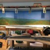
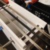
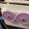
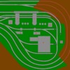
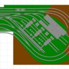
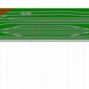
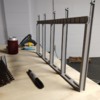
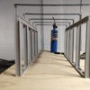
I cleared the last corner of the layout side of the basement. That means that a few coats of paint and I'll be about ready to start bench work. My last layout was over a decade ago, 8' x 8', loop with some sidings. This project is much more ambitious. I've been staring at the track design for at least a year; going over it again and again. I wanted you guys to take a look at it and tell me where you think I messed up or went right. I'm pretty set on this design but I know I have a habit of talking myself into having blinders on. Outside opinions fix that. I do occasionally sacrifice realism for play value but that's an important balance for me to achieve. I like to run my trains but I like when they look good.

EDIT 1/18/2022: I changed the name to Newport Railroad. See page 6.

The layout is fictional. I came up with the name Norgeville for the city as a kid and I decided to keep it for nostalgia reasons. The railroad largely serves the Norgeville Iron Works by delivering raw materials and supplies while hauling away product and waste. There are other small industries too. It's located somewhere along the border of Ohio and Pennsylvania (I'm from Youngstown) and competes with the mills in the region in the 40s and 50s.
The mine (unnamed) is at the top of the picture including the numbers 8, 9, and 13. It will be a drift mine that can fill three tracks and store three strings of empties to be taken over and filled. There's also a spare track under the mine. Four loading tracks seem like a lot so it's fate is undecided.
The mill yard for incoming/outgoing cars will be 16. The yard office is 12.
The blast furnaces are 1. The yellow spot above 1 is the pit for the skip hoist. I'm working on a rotary dumper for the cars to empty into the pit. I haven't seen a rotary dumper here in the Youngstown mills from my research so far but I think the nearby Hubbard furnaces here were loaded from the car, into the pit, like this in the late 1800s. I didn't see a big ore yard in the few photos I have but I'm hoping the Sanborn maps might show that no ore yard existed. I haven't been able to do more archive research on this because covid and life stuff. I'm pretty sure ore yards were the way business was done in the 1940s and 50s so this is either, an old mill, needs a backdrop of a ore yard and ore crane, or I'm claiming artistic license because dumping coal is fun and I don't want to buy operating hoppers haha
The dust collectors are 11. Covered hoppers will go under them to haul away dust from the blast furnaces
5 and 6 are boiler houses or maintenance shops, haven't decided. They'll take up some freight either way.
2 is the incoming liquid iron and solid scrap for the open hearth. I might need to squeak an extra track for tanker cars for fuel but we'll see. Maybe the fuel will be piped over from another siding. It's another freight opportunity
3 is the tap and teeming side of the open hearth. There will be some height difference in those tracks to accomplish that. I think that's the more prototypical way of doing it but I need some more research on it. It's tricky because I've never seen a functioning blast furnace or open hearth in person and up close. I need to get down to the Carrie Furnace in Pittsburgh. That will help with the blast furnace but I might be out of luck on the open hearth.
4 is probably the rolling mill but I'm not sure. It might end up being a forge shop. A coke oven would be interesting but I'm open to suggestions overall. I like a rolling mill and forge because there's lots of potential animated action. I've been to both and they were exciting.
7 is miscellaneous industries to give the layout extra purpose. They could be anything that requires freight cars.
14 is a track that might go to a lower level for staging OR for a suburb. I have some suburb buildings I want to use. I just saw a topic saying command control systems get cranky on multilevel stuff. I know zero about that but now I'll need to learn. There's a whole plethora of other problems that come with that (7% grade, table supports, etc) and I'll likely cover it in another topic. I think I want the option to have a lower level down the road but I have no intention to build it now.
10 is actually a dead end. I saw a trick where you put a mirror there and it creates the illusion of a track going somewhere else. I really love that idea because it helps destroy that sense of looking in on a closed loop world. The placement isn't permanent. It's more so there so I remember to use the trick.
I drew this in Atlas track. I have bought some Atlas track off ebay when the price was right but I've been leaning towards Gargraves lately because it seems the selection is better. I believe it's what Mercer Junction has and I think it looks good. I'm pretty undecided on what to do. I have 0-72 curves in there now so I can run anything on the main line. I might go up to 0-81 because what's 9-ish more inches?
The brown will be mountains. I was hoping to avoid the overhang of locomotives on curves so I hid the curves in the mountains in some spots. I also want to use the mountains in the middle of the layout as a divider to give the layout a bigger feel. The areas where tracks overhang the corners are bridge opportunities. I have two wooden bridges my grandpa made me when I was a kid. They have a humorous story behind their color scheme and they aren't exactly scale but I plan to use them because I like them. They were built by hand and now I realize how many hours he sank into them...it kind of blows my mind.
I plan to be able to run this layout solo or with a group. I enjoy the idea of one coal drag making laps while switching is done at each end of the layout or in the middle at the industries. I also plan to use live coal/ore/limestone loads from the coal mine/staging, into the hoppers, to the blast furnace, and rotary dumped. The dumping would either go through the table or, hear me out, into the skip hoist, up to the furnace, and into the furnace and then through the table. I've been tinkering with the blast furnace design and it could happen. I already planned to have the cars move. Why not give em a job? I also have already 3D printed from ingot molds and ladles for teeming. I would LOVE to be able to pick them up with an overhead crane but I'm getting off topic because I'm excited. Anyway, I just really dig the idea of live loads and I intend it to be a major part of this layout.
Phew, I'm done. I'm sorry for the novel.
What would you guys add/subtract to this layout?
EDIT: I didn't know I could upload Anyrail files so I did! That's convenient as heck. I'm using Anyrail 5 (yes, outdated, I know but oh well).
As far as the area in the basement, this layout stretches end to end against the longest available wall. The two white rectangles along the top of the photo are part of the wall and not removable. That's the only tricky business. I plan to remove conduit that's overhead and along the wall. There are glass block windows near the top but I wasn't worried about those. I plan on putting up drywall or something and making it look like the sky because of the height of the blast furnace. I feel it will kill the model if you look upwards at the blast furnace top and don't see something like a sky behind it. I would love to hear other people's thought on this. If I don't add a lower level, the height of the layout could be brought down to keep all observation at eye level or lower. But then I lose a potentially awesome operating feature going down to a second level.

Attachments

Images (1)
  • NIWShelf3Top
Files (1)
Last edited by BillYo414
Original Post

Replies sorted oldest to newest

A few suggestions / comments; first, attach an electronic version of your trackplan for those of us who might have the same software so we can provide you with examples of modification suggestions.  Second, provide a detailed description of the area where you plan to build, including  dimensions, windows, doors, interfering infrastructure (poles, utility locations, etc.), and anything else that might limit your use of the existing space.  Third, I noticed you have built in only one reversing loop on the right hand side; one on the left side would be operationally better.  Fourth, plan for access to your lower level now because 7% grades are way too much; try to limit yourself to 4% (and a 2% limit would be even better).  Fifth, switches under mountains are a recipe for maintenance disaster unless you build removable hatches into the mountain tops and have easy access to those hatches.  Sixth. your yard area near the mills ends up with tracks way too close to each other; not the way you might expect.  And finally (I feel like I'm writing my own novel in response), what about engine facilities which always add a lot of operational fun as well as storage space for your future acquisitions?

Recommendation:  Use the largest curves you can fit in your space and still meet your operation objectives.  All of your equipment will look better on those curves.

Chuck

Last edited by PRR1950

Well depending how detailed you want to get,  you might want to track down one of the books on steel mill modeling.

I worked in the steel industry for 18 years, but in a support role as an Industrial Engineering, so I have very high level view of the flow and operations of the various elements you describe,

As mentioned, dimensions might help.   A Blast Furnace is a big thing, so do  you have space for 2 or would one done well be a better idea.    John Armstrong recommended rather than do 2 or 3 small versions of something, do one and do it right.    That said, the blast furnace does NOT use coal, it uses coke.    Many mills had their own coke oven complex.   Armco where I worked had Sumit Solvay next door providing coke at Both Ashland and Middletown works.    The coal hoppers would go to the coke plant, and then the same hoppers or large ones would move the coke to the blast furnace.    The track behind where the yellow pits are would not work that most likely.   And it would be most likely be two tracks.    Hoppers with limestone, ore (or ore cars) and coke would come in on that track and dump to bins I believe.    those tracks would be elevated and most plants called them the "High Line".   A skip car (I think it is called that) would run along a track below the bins and load up the materials then run to the skip hoist pit and dump them into the skip bucket.    This was big electrical powered bin type car that ran back and forth.    The tracks were 2-3 times wider than RR tracks.     Most plants stored Ore on the ground because not much shipped when the great lakes froze if the ore was coming from US sources along the Great Lakes.    PRR mostly shipped ore in regular hoppers but they were only about 1/3 filled because of the weight of iron ore.   

The casting floor of the blast fce might be about the level of the High Line and was floored with sand.   If  you are  using Bottle cars then  you would not cast pigs on the casting floor.    The fce would be tapped with the molten iron going into the bottle cars.    The bottle cars would then be moved to the open hearth in your era and dumped into the open hearths as a charge.   You might have a string of 2-4 bottle cars per shift depending on size.   They probably did not use as much scrap in those days in Open hearths.   Scrap charges tend be more common with electric melt facilities.     

The Open heart would make the steel  using the iron and the heating and other additives.   Not sure about coke here.    I have never seen an open hearth fired from fuel from tank cars.    Ours were using natural gas, or gas from the coke ovens.     But it might have happened someplace.    As far as I know the J&L mills I worked in during college did not get fuel for open hearths in tank cars either.     The open hearths take about 16 hours to make the steel, so  you need a bank of them to get a tap about every 1-2 hours.    All the ones I have seen tapped into ladles.    The ladles were then moved by overhead crane to a teeming aisle where the steel was poured into ingot molds sitting on ingot buggies.    Ingot buggies are short 4 wheel very heavy duty cars that hold about 2-3 molds apiece.    These are running on regular RR tracks.   

The Ingot buggies would be moved, allowing time for the outsides to cool a little to a stripper shed.    Here a crane would pick up the mold and move off the car.   Then a large ram would push the cast ingot out of the mold.    the bottoms of the molds were platforms not attached to the mold.    There would be ingots stacked around.    As the ingots were needed, they would picked up and put in soaking pits.    These were gas fired ovens sunk in the ground.   These would be filled with ingots and again fired for many hours to get the ingots to a uniform temperature for rolling.     The ingots would be taken out of the pits and transferred to the slab mill.    Myabe again using the buggies, but more likely very hearvy duty flatcars.     The slab mill was usually a big reversing mill - it would tall but not many stands.    The ingot would be put on the rollers into the mill and rolled back and forth and formed into a slab of uniform thickness.     The slabs might be 8-10 feet wide I guess and maybe end  up being 40 feet long and 6-8 inches thick.         These then would be moved on the heavy duty flats to the Hot strip mill.   they might sit on the ground awhile but better right away so they don't have to be reheated.     The hot strip mill would roll the slab into a sheet 1/2 inch or less thick in most cases.   The hot strip mill would be continuous rolling, not reversing so it would be longer with many more stands that slab mill.    

The Hot Rolled is a finished product for some mills for some uses.     The rest of the hot rolled is moved to the cold mill where is rolled into a finer finish much thinner product for sale.    cold mills is what produce the product for auto body parts for example, or refrigerator wrappers.     This is the very good product with tight controlled specs for metallurgy, and thickness.   

In each step output might be inventoried, with the exception of the hot metal in bottle cars.    In your era there no, or very few continuous casters with steel going directly to slabs.    Also, there were few Basic Oxygen Furnaces (BOFs) to replace the Open Hearths.

Some plants produced blooms (large squares) instead of slabs and they went to different types of products such as pipe or structurals such as I beams.    Also some mills used the slabs to produce plate for fabricating structurals ship building

The mill complex is a railroad job in and of itself.

Think about including some "staging" where you send trains of loaded cars and where you might originate coal trains or coke trains.       You would also have trains of incoming empty gons and such for the mill.

I agree,hidden switches will be first ones to malfunction - murphy's law.

@PRR1950 I appreciate the novel! I'm looking for discussion. I could add a reversing loop to the left side. What's the advantage that I'm overlooking? Just being able to reverse back onto either line?

The 7% grade is if I ONLY go put the grade on a straight section. A curved grade would allow me to move closer to that 2% mark.

Tunnel switches were going to have little access holes next to them. Maybe I'm underestimating the real estate I need to get in there for maintenance? 

I was definitely struggling with how close I can lay tracks together for straight yards. I probably have more than I need in there right now and dividing the width of a track between a few sidings will hopefully get me the room I need. 

Engine facilities are likely to find their way onto the lower level. They do present some solid opportunity for modeling and convenient engine storage. 
 

@prrjim I have the Model Railroader's Guide to Steel Mills. It helped a lot. 

One blast furnace would open up real estate for other mill facilities. I planned to model a blast furnace with a dust collector and 3 ovens. A cast house comes out of the blast furnace. This plus a skip hoist fits on the table as shown. It's a little cramped but that's how things were built here. 

Did older blast furnaces use only coke? I know the stone ones didn't always but this isn't that obviously. Maybe I could swap out the mine for a coke oven or have the coke oven off-layout. Do you have a ballpark height on a high line? It would be awesome to work that in and would probably make it easier for me to slide my skip hoist in under the tracks. 

The tip on 1/3 fill for ore hoppers is handy for being more realistic. I wouldn't have thought of that. I planned on 3 bottle cars and 3 slag cars for a tap. I haven't figure out what my bottle cars would actually hold so I'll have to see if that works on the time table. I know what ours held at the foundry and mine are similar to those. 

I thought oil and natural gas was used for heating open hearths but maybe I got it wrong. Were the open hearths always on two levels? or did they tap into ladle pits? A 16 hour cycle explains why they had a miles worth of these things. I didn't realize that was the timeline on those. 

I wouldn't even want to begin trying to model a continuous caster and BOF buildings are enormous from what I've seen. I think we still have one in Youngstown and it's....dang haha

I'm inclined to agree that I need staging based on what you pointed out about coke ovens. I might be able to sneak it behind some shelves I have nearby. I'm really liking the thought of having a forge/rolling mill but I think the coke ovens are going to be important. A coke oven backdrop still requires staging for coke cars. 


Thanks for the help guys! I literally thought this was 99% done but I'm glad I asked. I hadn't thought of a number of these things. I'm also jealous of your experience @prrjim. I don't see myself seeing that stuff in person ever. I think Russia has the last running open hearth. 

Re: another reversing loop

If you start a train around your oval clockwise, you can, with one reversing loop, change its direction to counter-clockwise.  Now, however, the only way to change that same train's direction back to clockwise would be to back it through the same reverse loop.  Reversing an entire train through a reverse loop can be done, but not without occasional headaches like derailments (why I worried about the hidden switches).  It doesn't look like it would be too hard to arrange a second (opposite side) reverse loop through some of your mill trackage.  Then you can have your train(s) running in opposite directions after a couple of rotations almost automatically.

Re: grades

So, start your grade in the loop, but don't start it out at a hard 3%.  Use a vertical easement for smoother and safer operation (e.g. start with 1%, then 2%, then 3% with finally a little bit of 4% before gently scaling back down to 0).

Re: coke ovens

Why not model them as photo dropbacks on your north wall instead of some of the other industries you were considering?

Finally, search on the forum for Steel Mill modeling and look for posts by a fellow going by Roo; his photos and posts provide wonderful steel mill modeling tips.  I think his real name is Neville Rossiter, and I believe he now mostly posts on a steel mill modeler's Facebook page.

Chuck

Last edited by PRR1950

@PRR1950 ah, the reverse loop thing makes sense now. I see what you mean. That would suck so I'll find a way to add one. 

I will transition slower for the grade. I'm not opposed to genuinely needing helper locomotives to get up the grade. I feel like it would present an interesting operation. There's a guy on YouTube with an HO layout and he has this exact setup. They can do it with a 3 diesel lashup but it works better if they add a helper to the back. I thought it was cool. 

I was talking to a buddy last night and I actually think I'm going to model abandoned beehive ovens at the coal mine. I'll base them off the beehives we have near me in Lisbon. Then I think I will use a back drop where the three industries were and use that siding for loading/staging. 

I will look him up! Thanks! 

I never heard of a blast furnace in the 20th century using anything other than coke.    

NO matter how much space we have, we can never fit everything in.   For that reason I would not model the coal mine.    I would include the coke ovens and bring the coal in from staging.    That way, you have a move to bring coal hoppers into the coke plant.    Then you load the coke into hoppers and move it to the blast fce.    Now many RRs had coke hoppers with extended higher sides because coke is lighter than coal.    So you might have captive cars in two strings that move back and forth between the coke plant and the Blast fce.    The coal hoppers would than go back to staging empty, so you need two strings of those too, if you want to run that way.

I am thinking the "High Line" would be about 1 1/2 car heights above the track where the bottle cars are spotted.    That is above the level of the casting floor, which is a level above the bottle cars.    So you could place it at height to get your skip underneath.   This makes sense since the skip would feed from stuff that comes in that line.    Yes there are a few photos around of Ore in coal hoppers and it is just a little on the bottom of the car.    PRR did not get into Ore jennies until late - I think maybe the 60s.    Other RRs  probably followed different patterns.   The P&LE (NYC sub) was a big player in the area you are interested in.  

The bottle cars capacity gets bigger and bigger as you move through the 20th century.   I think they got up to 250 ton capacity.    However, even the smaller models look big.    you can use them with your furnace and few people will look twice.    Another thought consider 4 bottle cars.    2 at the Blast fce and 2 at the Open Hearth.    When you tap the blast fce, you move the two loaded ones to the Open Hearth and bring the 2 empties back to the blast fce. 

By the way, I got into this at the end of the open hearth era.    Armco was phasing them down as they got better and better with using casters and BOFs.    This was in the 70s and 80s.   I did a lot of projects on caster operations to study multiple casts without resetting the caster, which took about an hour at Middletown.    We could cast a heat in about an hour too, so if we had to reset the caster we lost an hour production.   But if we could piggy back heats one after another, we could produce a lot faster.    To do that we had a 10 minute window when the ladles could be switched while the cast ran with the material in the tundish.    If we could not make the window we had to send the heat to the teaming aisle and use it in the Open Hearths.    That 16 hour cycle was a number I remember from our middletown plant.    Other plants may have been more or less, but in the ball park I think.    With the BOF, our tap to tap time was 44 minutes!     That number is etched in my old mind!

Yes all the open hearth firing I have heard about was gas or oil.     There is gas produced as a by product of the coke operation which is why they want it close.    However, I think it was much lower BTU content than natural gas so had to be supplemented.    They also used the gas from the coke overs to heat the hot blast air for the Blast fce.

All the Open Hearths I am familar with, just a few, tapped into a ladle and as you say probably held in a pit, but probably never let off the crane.    The tap does not take long relatively.

This info will save me hours of reading at the archives. Thank you so much! 

I kind of like the idea of having the coke oven where the mine is. Then enforce that lower layer. Put the mine at one end and the town at the other. It would give some distance to cover if I enforced one lap around the loop between all locations. Do you guys think that would give a feeling of distance? The coal train would head out from the mine in the lower level, make a lap on the lower level, then catch the grade up to the coke plant, drop off coal hoppers and pick up empties. Then a lap on the top level before heading down to the mine. Same thing at the coke plant. Leave with coke, make a lap, then drop off at the mill. Pick up empties, make a lap, and go to the coke plant. 

Here's a link to the type of ladle pit I'm describing: http://www.stahlseite.de/eec10.htm

Last edited by BillYo414

Bill, I don't know anything about steel mills, career was in electronics with power and telecom utilities, but being from Butler County, Pennsylvania they were all around.

I had trouble with the grades on my under construction layout.  I thought I had provided enough vertical easement to my 4% grades (yes it's a small layout).  All my cars are 40-foot boxcars, 2-bay hoppers, and short tank cars.  My engines aren't very long since I have 054 curves, but some would negotiate the tops and bottoms of the grades, and some not.  I had to rework them and they seem okay now except the pilot on one 2-8-0 bottoms out at the base of one grade.  That still needs some work.

I'm glad you now see the need for the second reversing loop.  If you have one, you need two.

I will look forward to seeing how your plan and build progresses.  You mentioned Mercer Junction.  Are you still in the Youngstown area?  I live in Butler which is southeast of Mercer.

@Mark Boyce posted:

... had to rework them and they seem okay now except the pilot on one 2-8-0 bottoms out at the base of one grade.  That still needs some work.

I'm glad you now see the need for the second reversing loop.  If you have one, you need two.

I will look forward to seeing how your plan and build progresses.  You mentioned Mercer Junction.  Are you still in the Youngstown area?  I live in Butler which is southeast of Mercer.

That's a good call. I read that in another post when I as searching for info grades but forgot it. I'll rework my track plan to include this because I definitely went zero to incline. No easing. 

I am! I'm pretty much an ambassador of the area. People say it's terrible but we have come a LONG way in the last 20 years since I was a kid. I chose to stay after college and have no intention of leaving haha I've been to Butler a few times. I ate at the Chop Shop. I work about 20-30 minutes southwest of Mercer in Pulaski so I make a side trip once in a while after work when I need something. I'll be headed there to pick up a DCS system on the next paycheck. Can't wait!

Bill, My daughters and their husbands like the Chop Shop.  Most of the food is a bit strong for my old stomach, but they must be good.   They do a good business.  Yes I am familiar with Pulaski.  Also, I am aware Youngstown is doing a lot better.  You will like DCS.  Like anything, It does take a little getting used to, but help is always at your fingertips on this Forum.

@Mark Boyce I'll get a hold of you to run some trains when the railroad is built haha I'm mostly excited to get DCS because my MTH Triplex won't run in conventional. It runs in DCS though. Not sure what to make of that but we'll go with it. 

I'm working on my track plan for the coke plant where the coke plant is a back drop. I feel like scratch building a coke plant could take a while based on what I'm seeing in the real world. I'm currently flying around on Google maps over Warren, OH and Neville Island looking at the coke plants and I'm not seeing anything obvious where the coke is loaded for shipping. I know there's a car that catches the coke when it gets pushed but how does it get into the hoppers? Is it just a tipple? I currently just have a long siding where a train could be loaded and I'm not sure if that's enough. 

@BillYo414 posted:

@Mark Boyce I'll get a hold of you to run some trains when the railroad is built haha I'm mostly excited to get DCS because my MTH Triplex won't run in conventional. It runs in DCS though. Not sure what to make of that but we'll go with it. 

I'm working on my track plan for the coke plant where the coke plant is a back drop. I feel like scratch building a coke plant could take a while based on what I'm seeing in the real world. I'm currently flying around on Google maps over Warren, OH and Neville Island looking at the coke plants and I'm not seeing anything obvious where the coke is loaded for shipping. I know there's a car that catches the coke when it gets pushed but how does it get into the hoppers? Is it just a tipple? I currently just have a long siding where a train could be loaded and I'm not sure if that's enough. 

Bill, That sounds like a good plan.  Thank you!!

Here is a link to the coke plant at Clairton, Pa. https://www.ussteel.com/locati...works-clairton-plant My uncle worked at the Edgar Thomson plant an engineer in the 50's and 60's that is part of this complex on the Monongahela River.  Maybe that location can give you some ideas.

You asked a question about control system signal interference when multiple levels are used.  I'm no expert on that subject (in fact, probably not an expert on any subject except federal income taxes), but I believe multiple levels only generate problems for TMCC.  The usual recommendation is to wire a ground plane under each level's track (some use aluminum screening, some just string plain wire) so that it's not visible but close enough to be useful.

I also noted that you will space the levels between 20" and 24" apart.  To do that, your upper level will have to be higher than where most like to work and/or view, or the lower level will have to be lower than most prefer, reducing under layout access and storage.  Also, try not to put anything other than scenery in the middle of your lower level because if you have to reach in too far for maintenance matters, even a 24" separation will feel tight for your head and body to occupy.

Chuck

Last edited by PRR1950

Interesting. So it's possible but you need to ground each operating plane? I can work with that. I just don't want to set myself up for problems that can't be resolved. 

I was planning to have the upper level at about 45". I setup a test layout at 48" and feel like it's pretty good. I especially like it because it elimates the aerial view feeling. Obviously I'll have that feeling on the lower level but I'm not as worried. I have chairs and stools that will make 20-24" a good level for viewing. I'm most worried about needing to work on the underside of the top level for anything. I don't think 24" allows enough room for a topside creeper and myself. That's going to be tricky business. But I'm confident. More complicated problems have been solved. 

UPDATE 9/6/2020

I attached the updated track plan. I decided Ross Custom Switches were worth a look after using that handy "search" function on the forum. Man am I glad I looked! They have such an awesome selection of special tracks to give you more efficiency in your yards and whatnot. Unfortunately, I had already started collecting bits and pieces of Atlas track so I'm just going to combine the two. 

One concern I'm having is track clearance. Someone brought it up before but I was convinced I had enough space. Now I have some real tight spots. The cross over on the southern reverse loop has a track sneaking by it and that's probably the worst case. I might shimmy the cross over up to make space or scrap the extra little track there. It's on there so the switching engine can get access to the rest of the mill from that side of the layout without having to go through the dividing mountain. I planned to have a backdrop extend from the mountain to totally split the layout in an effort to make it seem bigger. It's tricky knowing how much clearance you need without having everything on the table in front of you. I want to make the tracks close because I know the yards at Youngstown Sheet and Tube were crammed tight. 

Beyond that, I was able to add an ingot stripper building (17) and extra sidings at the coal mine for storage thanks to changing what switches I use. I decided to keep the coal mine, coke oven, and mill all on one level. I was doing some research on coke plants.....they're huge! With jaw dropping intricacy. I'm going to leave that as a back drop. The loading will come out of the wall because I think it should be simpler than all the supporting equipment that goes with a coke battery. The mill is complicated enough. I did find myself relying on flex track pretty often to make up for minor misalignment. 
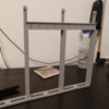
On a less related note, I found out Lisbon, OH (near me) has old school beehive coke ovens that you can visit. I think it would be an awesome modelling opportunity to model some abandoned beehives in the mountains near the coal mine. Likewise, the Hopewell blast furnace is here in Poland/Struthers, OH. It, and another stone blast furnace in Youngstown are accessible. Allegedly, the Montgomery furnace is in Struthers but I haven't found it yet. These stone blast furnaces stood here while the modern mills cranked out steel for nearly a century. I want to model them as well in the hills. So I'll be headed out here with a tape measure to get some real life dimensions before winter comes along. 

I still haven't even started thinking about the lower level. I got the walls scraped and washed this weekend. I went to pick up paint today. Carpeting will be the next step after painting. The ceiling will follow and then bench work!
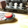
Attachments

Images (1)
  • NIWShelf3T2 - RCS
Files (1)

UPDATE 9/8/2020

The attachments include initial track plans for the bottom level of the layout. I was hesitant on the two level design because of storage reasons but I was disappointed that the yards on the upper level were dedicated to industries. No yard for making and breaking general freight trains. Plus there are a number of structures I have for a town that carry sentimental value for me and I would like to include them. So it's looking like a city at the top end, yard in the middle, and then possibly an engine servicing facility to be added later. That's one scenario. 

The other scenario is to move the coal mine to the bottom level under the steel mill so that emptied coal can be sent down to the coal mine directly for reloading. I'm very much entertaining this because a small conveyor system from the mill to the coal mine would be 40' long and possibly pricey. A pipe could be camouflaged in plain site to the coal mine and would great simplify coal loading. 

That just leaves the elevation question. A discussion in another thread on banked curves got me thinking of getting rid of the elevated track that goes up 24" at a ~3.8% grade. I'm not considering just using a single track elevator on the left side of the layout behind a backdrop. I think it could be 100% hidden. We'll see. I'm on lunch at work now. Maybe I'll find some to tinker with the design tonight. 

This is becoming a heck of a project haha

Attachments

Images (1)
  • NIWShelf3Bottom-RCS
Files (1)

Bill, While my two grades of ~4% to gain 6 1/2" in elevation do work for my short trains (6 cars), some engines do tend to throw traction tires going upgrade.  Others do not with the same load.  I just built these grades this past winter.  I'm hoping new traction tires will solve the issue on 10 to 15 year old engines, but it is too soon for me to tell.

@Mark Boyce posted:

Bill, While my two grades of ~4% to gain 6 1/2" in elevation do work for my short trains (6 cars), some engines do tend to throw traction tires going upgrade.  Others do not with the same load.  I just built these grades this past winter.  I'm hoping new traction tires will solve the issue on 10 to 15 year old engines, but it is too soon for me to tell.

Well that's reassuring. I feel like I either get exciting operation requiring skill to operate if I go with the grade, or really slick operation with the hidden lift table. The entrances and exits with the lift would both be in a mountain where they can't be seen and that will totally add to the concept of distance if I set that lift to move slowly. So I think I'm going to be happy with either solution.

6 cars is reasonable and prototypically, trains were split to get up Salida grade so it's not like it's THAT unrealistic. It's more an appearance issue I think. 

I have an 0-8-0 that throws traction tires like a toddler rejects vegetables. I ended up cutting them off for the time being but that sure can be irritating. The engine weighs enough to pull empty cars with ease without traction tires but I wanted it to pull switching duty at the mill and those cars will be heavy. 

You got any pictures of your grade Mark?

Here you go, Bill.  You can only do so much with an 11x11 room with two doors and two windows.

I made the inside loop on trestles so I could see through to the town and outside tracks.

2020-08-27 12.31.10

In the upper right you can see the near track going down to the right and the rear track going up to the right.

2020-08-27 12.30.58

Another view of the trestle.

2020-07-24 17.20.49

The caboose is near the top of the rear grade.

2020-06-30 12.07.332020-06-01 16.20.21

Here it is before I started putting in the trestle.

2020-05-09 17.55.42

Attachments

Images (6)
  • 2020-08-27 12.31.10
  • 2020-08-27 12.30.58
  • 2020-07-24 17.20.49
  • 2020-06-30 12.07.33
  • 2020-06-01 16.20.21
  • 2020-05-09 17.55.42

Still a good looking layout @Mark Boyce. I feel like the grade looks fine. I was imagining much steeper looking! Thanks for grabbing the pic. I needed some reference Mercer Junction doesn't have a significant grade for me to reference. I'm tinkering with the elevator idea now. Someone recommended a helix but I had an engine shed in the spot the round house would need to go in so I really don't want to give up the real estate if I don't have to. 

I'll have to do some learning about the Blackwater Canyon Line. Is that near us in PA?

Well after a long night on Anyrail, I think the elevator system is going to work in terms of track. Now I just need to come up with a way to lift the track so I can see how much space that will take. I'm basically trying to stay under 5" wide. We'll see. 

Meanwhile, the basement wall remains unpainted haha

Bill,

The Blackwater Canyon is the Black Fork River in Northern West Virginia.  The Western Maryland Railway had a line from Elkins, WV to Cumberland Maryland.  You can find the Blackwater Canyon on a map with Thomas WV at the top of the grade and Parsons WV at the bottom.  It is now a bicycle trail.  Blackwater Falls State Park is at the top also.  

It's not an exciting update but it is pretty important. I found an empty bottle of automotive body filler in the basement and I'm 99% sure that's what the previous home owner put on the walls. It's either that, or he painted the basement walls about 30 times because there's a layer or something on the walls that isn't quite a quarter inch thick. 

Regardless! I have finally finished removing all the loose chips/paint/filler/who knows and wiped down the walls to remove the dust. That means the two towers of sealer and paint are up next. 

You can see the two cement block areas that stick out from the wall to support the beam that spans the house. I wish I could get rid of the but I'll pass on that. I'm planning to use that area to install a lift track behind the backdrop and scenery to get between the two levels I'm dreaming of. The temporary test table is behind me. 

Like I said, it's not a particularly exciting milestone for spectators but I'm excited to get to this point. There was a big wooden shelf in that far corner that was a bunch of nail held together and it was a rough demolition job to say the least. So! Hopefully some painting is in my near future. 

Attachments

Images (1)
  • IMG_20200913_133040466

I hope what you removed from the walls wasn't WATERPROOFING?  In my case, what I started to pull off was something peeling called hydraulic cement, previously painted an ugly blue.  Fortunately, after I saw the damage removal was causing to my concrete brick basement/foundation walls, I stopped removal without doing too much damage.

Chuck

I don't think so (meaning, I hope not!). It didn't work worth a crap if it was waterproofing. The basement was very damp until I fixed a downspout. Plus the paint was flaking off. The sealer/primer I got is supposed to be waterproof and I used a latex paint to help ensure that. At least I think that's what will happen. I never claimed to be a painter haha there was just loose chunks. I used a wire brush and putty knife to get all the loose bits off. 

I'm going to go ice my shoulder now! 

Last edited by BillYo414

I actually got one recently but the paint damage has been done. The house was unoccupied and shut for two years. The yard sits low and I put in french drains last summer. That made an enormous difference on its own. 

I think the humidity down there is starting to level off. It's been sitting at 50% for about three weeks now. It read 70% when I first plugged in the dehumidifier. So I think I'm headed in the right direction. I do wonder if I'll need to get a second dehumidifier to keep under the layout.

The first coat of sealer primer is on. I suspect I'll need a second coat but it needs to dry before I can tell. Painting should move faster now. Covering bare concrete spots and everything always takes so long because the paint is just absorbed. Now I can move much faster since I'll be going over a smooth sealed surface. 

In other news, I got me an MTH hopper and DCS System from Mercer Junction. Command control is awesome!! I never thought I would enjoy a loop of test track so much. The hopper has opening bay doors under it and I'm definitely suddenly interested in getting a fleet of those instead of doing the rotary dumper I had originally thought I would have to do. I'm just trying to find out if all Premier fish belly hoppers had these doors or not. It isn't called out in the features and I hate to assume. We'll see what's up. Maybe I'll have to buy another and find out haha

Attachments

Images (1)
  • IMG_20200919_153157012

Bill, the paint job looks great!

Some of my Premier fishbelly hoppers have opening doors, and some don't.  I actually wasn't sure, until I checked them all just now.  Come to think of it, I ordered the 6-pack of Western MAryland hoppers from the final MTH catalog but it doesn't say if the doors open.  Without an actuator to open them, you would have to do it by hand anyway, which isn't objectionable anyway.

Today I went and got my coal. I decided to use the abrasive coal slag from TSC. It looks great in my opinion! My favorite part is how easily it slides out of the fish belly hoppers like the real deal. 

Now I'm going to do some thinking out loud. 

I've been resisting the idea of going with a helix at the nothern end of the layout to connect the bottom and top level because I felt like it was a waste of space where cool things could be modeled. That was before I started collecting hoppers with opening hatches in the bottom. Now I'm thinking the helix would be perfect because it would be a lot easier to build than a custom lift like I had planned on. It also means that when the hoppers empty at the steel mill, that load could easily be funneled down through the helix, out of sight, and go into the coal mine on the lower level where I can then fill hoppers again. This would allow for continuous operation and I'm very excited for this possibility. A guy by the name of nsmodeler24 on youtube has a similar setup involving a rotary dumper but I couldn't find the video showing them connected. Life and work have been beating me down pretty hard lately for whatever reason so it will be nice to sit down on Anyrail with the dog and just work out the plan for the next few nights while I try to catch some downtime without any surprises. My only concern is the weight of a coal drag going through a helix. I'm not concerned at all about motive power. It would just be a biblical mess if the hoppers stringlined on the helix!

I'll post the track plan when I get it figured out. 

It sounds like a good idea, but I agree I don't know how many cars and how much power it would take to pull them up the helix.  You can work on Anyrail and if you think that is the way you want to go, then I suggest you build a small temporary setup to try out the idea.  That is how I learned I could pull my short trains up a 4% grade.  I built one on the floor and tries every engine on it.

I don't have anything to show for improvements but it's been nearly a month and I still gotta burn 15 minutes at work.

I worked out how much carpeting I need. Now I need the Norgeville Railroad board of investors to fork over some cash haha

I'm working on modeling and prototyping those models on the 3D printer since carpet isn't in the budget. The current item is the car dumper for behind the blast furnace. It might be dumping ore, might be coal, should be coke or limestone but whatever; the end goal is to push hoppers (fish bellys) up to the high line and dump them at the furnace. Atlas and MTH 55ton fish bellys have opening doors and my hand tests show the coal mostly falls out. It might need a little help but that can be solved later. I will need to convert the MTH hoppers to be spring loaded like the Atlas. MTH doors lock open and closed where the Atlas doors are held shut by a torsion spring. I'm having trouble sourcing the springs but I'll get there. I got a place to make custom springs since I couldn't buy them from Atlas but I need to get my measurements and whatnot figured out. I don't know the nomenclature for how to call out spring dimensions.

Either way, I cut the ties out of the track and it sets down into the top of the dump station. Then two axles are connected via gears on the outside. The axles have one finger each. The axles turn and the finger pushes the door open and the coal empties. I'll see about getting some pictures up when I get home of the rough prototype. It works. It just doesn't work well.

That's pretty much the extent of the excitement. I have decided to go with the helix for a number of reasons. The top reason is that the helix will be under the blast furnaces so I can hide the coal falling through the table and going back into the coal mine on the lower level. This will (hopefully) give me hands off coal loading and unloading. That should be a good time and I'm excited to be able to do that.
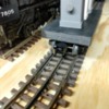
But it does change the entire dynamic of the layout. Half of the top level just opened up. Do I put a different industry at the end of the table where the coal mine was? Or do I say the heck with it and let the steel industry dominate the entire top half of the layout? That would be interesting!

That's all for now. Maybe I'll snap some pictures of the unloader when I get home. Lunch is over!

Bill, Please do take some photographs of the unloader for us.  I would like to see it.  Several years ago I bought an NIB Lionel 456 unloader with one car with the plunger actuator with the Lionel MSRP on it of...hold your hat...$18.50!!  I have no idea when it was made.  IT works slick, and I have a few other cars with the plunger.  I thought I could use it on my layout, and doctor it up a bit to look more prototypical, really just the base would need work.  That is one reason there was a lull in my layout build topic.  I finally decided I don't have room for it on this layout.

The helix sounds great too!  There are so many things to consider when designing a layout.  Remember, you can always change things around as you are building.  My layout is basically as planned, but I have been able to squeeze in a lot more than I thought!

Two photos are attached. Video coming. The finished unloader will be one whole piece. I printed it in a bottom and top section so that I didn't have to print the entire thing every time I wanted to make a change to the top. It took a few tries to get the side shields designed so coal wasn't splashing everywhere. Then getting the spacing right to fit the ties took two tries because I didn't measure twice like the rule says.

So the bottom has the through axle with bearings at each end. The bearings might be overkill but I figured it would eliminate wear and I wouldn't have to think about it ever again. The two gears are meshed and one will be driven. They are what flips the fingers. The fingers will need more work. A lot more work. They don't fold into the base so cars/trains will be unable to pass over them. I'll need to find a spot to tuck them but I think it will be as simple as a printed slot in the base. The unloader is tapered and the coal falls down it nicely. I'll have to see about adding a cavity ok the underside for an oscillating weight to help get the last bits of coal out of the car.

I assume arduino will be the way I'll control it. The main reason for that is I should be able to set stepper motor spin limits so anybody will be able to unload coal without me worrying that they break something on accident.

I took a day off Friday so I can go vote early and I hope I can finalize the design and print it. I'll post if I get to.

The videos show more detail of it working. It I'll have two fingers in time and I plan to make the fingers out of aluminum instead of printed prototypes.

The workbench is a mess because I've been so busy. It's not normal got things.... everywhere.

Attachments

Images (2)
  • IMG_20201021_170535147
  • IMG_20201021_170554115
Videos (3)
VID_20201021_170451405
VID_20201021_170409300
VID_20201021_170518975
Last edited by BillYo414

It's been a while since my last update. The holidays are a busy time for me. Especially this year. Covid has everyone bungled up so we're excessively busy at work. I also drive a tractor for some friends at their Christmas tree farm on the weekends. Somehow, I've been trucking along:

  1. The floor under the layout has been covered with ergonomic mats from everybody's favorite bargain hardware store so now table building can begin
  2. Research turned up that the Mahoning valley had something called block coal and it was mined from the ground and put right into the blast furnaces. I'm skipping a coke plant now.
  3. Research also taught me that there was a thing called merchant iron furnaces. These furnaces only made pig iron and that was sold puddling furnaces, then open hearths, and eventually bessemer converters. The last merchant iron furnace in the Mahoning valley shut down in the 1960s (which is pretty mind blowing).
  4. The above research made me scrap the original track plan and try something new where the furnaces are not necessarily right next to the open hearth and teeming, etc. That's still in process.
  5. I'm testing the unloader for the hoppers. I plan to post pictures of that as soon as I get the grade built to push the hoppers up to test it. Hopefully I can learn to program Arduino to motorize it.
  6. The blast furnace model is coming along. I plan to post pictures this week after I get a few more pieces printed and glued on. I had to shrink it and that's a bummer but it is what it is. Technically, it's still accurate if it becomes a merchant iron furnace because those were typically smaller.

I dismantled the Fastrack loop on the test layout and started putting the Atlas track down to see how I like it in terms of assembly, reliability, noise, etc. It is silent compared to the Fastrack, that's for sure. I haven't ran full speed just yet because I haven't got enough pieces to make a full loop but I expect them to be in this week.

I picked up some real deals online on conventional used locomotives. I would like to start converting them to TMCC/Protosound. I gotta be honest though, I'm chicken to start getting into all that. I've learned a great deal about electronics here and at work but it's been troubleshooting; not exactly installing. So we'll see. I'm looking for thoughts on upgrading conventional Lionel steamers to protosound or TMCC. I got two 0-6-0s and an 0-8-0 with railsounds that need upgrading.

Anyways, that's the news. Hopefully getting the table built will result in more steady progress. We'll see what goes.

Bill, That's a lot of good information you have dug up about coal mining and steel making in the Mahoning Valley!  Each area has it's own unique history, geography, geology, etc that can make anyone's layout unique.  I have not tried Atlas track, but I like the looks of it.  The solid rail and detailed ties remind me of HO and N scale track I used for years.  I'm sure it is a whole lot quieter than Fastrak.  I went with GarGraves track and Ross switches because Atlas had a real shortage a few years ago, and I was afraid of going with a product line that might not be there in the quantities I wanted in the future.  As it turned out, they fixed whatever problems they were having.

I'll be looking forward to seeing what you come up with when you post it!

I never thought about it like that but the block coal does add a unique element.

I like the look of Atlas but Gargraves is appealing. I'll probably buy a chunk of Gargraves and experiment with it soon. It would be great if I could chop a bit off the ties and thin them up. I can always put the Atlas that I have under hills and such if I decided to make the change. I still have concerns about getting Atlas but I haven't come up short so far when I check stock. I have two of their switches and I'm not impressed with those. Wheel flanges jump the track and I got dead spots everywhere. I bought them used so I'm going to assume they're damaged. Otherwise I figure it's from the era when Atlas had bad switches.

Well I defeated myself.

I used drawings from Youngstown Sheet & Tube's Campbell works blast furnaces to design the BF's for my layout. Now I worked for the Ellwood Group so I thought I knew large industry but those BF's were enormous. So much so, that the height wouldn't fit on my layout as I designed them. We're talking about just over three feet in height. Fortunately, my CAD program of choice has a "scale" command I was able to shrink that down to 75% of the height. But that means I created a confusing situation for myself I have managed to print half the furnace in real 48th scale, and the other half in 75% of 48th scale

So the update showing the model will be delayed. The printer is hard at work right now while I smoke a cigar and continue designing.

The track plan has completely changed though. This is mostly because of how shelving in the basement has already been set up as well as new information about Mahoning/Trumbull/Lawrence/Mercer county iron and steel history coming to light for me. It pays to do your homework as it turns out!

I attached a photo of the track plan for the blast furnace end of the mill and here's the ID of everything

15 - elevated ore track for coal, iron, and limestone. There should be two tracks but artistic compression current has me having one.

5 - blast furnace with stoves to the right and a dust collector over the tracks behind it (below it in the pic)

11 and 12 - canteens. We called them canteens at the foundry I worked at but they're just break rooms for lunch and safety meetings.

9 - hoist engines to pull cars up the skip hoist for the furnace

8 - blower house and maintenance shop

16 - track to the helix for the bottom level

12 - utility shack

I expect this plan to change a number of times over the next few weeks as more items come off the printer and head to the test loop but this is significantly different from the track plan I had posted before. There are now two mainline loops because I want the option to let trains run around a loop while I switch the cars for the blast furnace. I hope to have group operating sessions but sometimes it would be nice just to go downstairs and run some trains. The yard (not pictured) expanded a bit to hold incoming and outgoing cars. The open hearth/bessemer operations moved down to the other end of the layout but I haven't even started on a track plan there yet.

Likewise, I have nothing planned for the lower level yet other than knowing that a coal mine will be there to load hoppers. People have recommended a round house but I'm open to suggestions. I like operation, no doubt about it. Putting a yard on the lower level for other freight is appealing but time will tell. I anticipate that I will build the table on the top level first, get my loops setup, build a blast furnace, and then run trains just to scratch my itch.

Attachments

Images (1)
  • tb7BF

Here's the latest:

The final major component of the blast furnace is on the printer now. That'll give me the furnace itself, the stoves, and the dust collector. Shrinking the model down made for some mishaps in measurements and whatnot so I've had some reprints plus the printer needed a part replaced (no big deal, just lost time).

The benchwork is designed and I'm ready to build it. It's done up in 4' wide sections that will be no more than 6' long. I plan on never moving again but that's not realistic so I think I should be able to dismantle the layout pretty easy. I intend to cut track where the tables come apart and the wiring will follow suit. My hope is that un-drying white glue to remove scenery is small potatoes if your table is simply bolted together.

I found https://www.ohiomemory.org/. RIP the rest of your night if you like history I've been researching the Youngstown Sheet & Tube Campbell works to see what's in a blower house, boiler house, skip hoist, open hearth, teeming pit, etc. There are some really impressive pictures on there and I'm so glad I found it because the local industrial museum is tough to get into with the pandemic. This has helped me move forward and start coming up with some basic plans on the other structures for the mill.

The track plan has undergone some huge changes and it looks like I might be having 3 blast furnaces now instead of 2. The top level of the layout (mill level) will be very congested and I'm hoping this makes for more exciting operations. The iron operations take place at one end of the layout while the steel operations take place at the other. I intend to post the track plan once I finish getting it labelled up. I have some concerns about clearances and maybe having too much track but I'm not overly worried because I believe the most important sections are fine where they are. Everything else is negotiable. I'll be starting first with the giant double track main once the table is built. Partially to scratch my itch to run more trains and partially because everything else is located relative to it, the high-line for the blast furnaces, and the helix.

Which is the last update! I'm going to use a screw conveyor to get my coal back down to the coal mine on the lower level. I already test printed a two part screw that has to be glued together. It fit inside the clear PVC pipe perfectly. Then I test printed a piece that connects to the vertical pipe and feeds the screw.
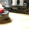
I have found the table grew in some spots that now means I can't reach everywhere on the layout without help. I'm a little worried about that. I know I can use a topside creeper. I think the layout will support my weight if I had to crawl on it. I mostly managed to keep switches within reach. The only three that are isolated can be reached via the helix.

So I've been busy. I don't have many pictures of anything to show for it but I'm trying to cover my bases before I start cutting and assembling. I thought my benchwork design was done till I went to double check some measurements today. Turns out I was way off. I'm glad I double checked. I'l try to get some pictures up at some point.

Here is a link to the Campbell works blast furnaces. This plant heavily inspired my new track plans. The furnaces there were also the original design of the model I printed. I got the blueprints from the museum and scaled them down to 1:48. Unfortunately, they were still enormous so I made scaled them to 75% of 1:48 and I'm going with it so far. Once the table is built and I start laying track, I'll decide if there's any room to make them slightly bigger.

Bill you are right.  I have eaten my words a couple times by saying I don't plan to move again unless it is to a nursing home. 

How many different facilities did Youngstown Sheet & Tube have?  I can recall hearing that name every so often in the years past.  I recall taking a evening river cruise up the Monongahela River on the Gateway Clipper and seeing the fire and glow from the blast furnaces along the way, but never saw what was around Youngstown, though it is about the same distance from home.  Even George G3750 has had to do some selective compression on his Weirton Steel topic. 

I wish someone else would weigh in on your topic.

I moved every 11 weeks for 5 years during college. I would love for my next move the last one you ever make. Then again, I say that now because my retiree neighbors are fantastic. They keep an eye on my place during the day and teach me how to tend the garden I started. Maybe I would feel differently if my neighborhood didn't feel like extended grandparents. I'm also not married yet. Hope I can find a girl that feels the same as I feel about my neighborhood.

Sheet & Tube had the Youngstown facilities (Brier Hill, Campbell Works, and the Rod and Wire mill in Struthers), the Burns Harbor Facilties, and some coke works in PA I think. I appreciate the Sheet & Tube works for the family connections I have as well as personal connections. (Pardon my rambling)

The Campbell Works were divided by the Mahoning River. That river basically splits Struthers and Campbell. Men from Struthers and Campbell worked at the mill and that boiled over into the Struthers-Campbell football rivalry. I'm a Struthers high school graduate. The mills closed in 1979 but we still hold that rivalry. There's a trophy for the winner and everything; it was the biggest game of the football season. It was good times.
My grandpa was the fire chief at Sheet & Tube. Him and another guy invented a way to refill spent fire extinguishers. I had uncles and cousins that all worked at the Sheet & Tube too. So I got loads of personal connection to the mill. My friends grandparents worked there with my grandparents and so on.

But that's enough rambling haha I'm glad model railroading lets me combine my love of history with my love of all things mechanical.


That poor 3D printer ran 24/7 from December 22nd to January 3rd while I was off work for the holidays and able to be home supervising it. The last piece is set to finish at 1AM tonight. Hopefully I can post some pictures tomorrow. I'll be looking for opinions on whether or not the stoves are too tall.

The coolest part of this project has been being able to create a fictitious city located in Mahoning County where the history lives on. The research has been a good time and I've met a lot of great people along the way before the pandemic messed things up.

I attached a pic of the north end of the layout where the blast furnace is:

18 is a maintenance shop for rolling stock and the engines

17 is the boiler house

16 is the track leading down to the helix. Concealed under hill.

15 is the ore track that empties coal/limestone/iron ore from hoppers

11 and 10 are lunch rooms, called "canteens" where I worked

9 are the hoist engines for the skip hoist

8 is the blower house

5 are the blast furnaces including three stoves and a dust collector on the tracks.

Attachments

Images (1)
  • tb8bf
Last edited by BillYo414

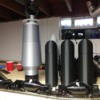
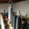
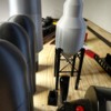
Here are three pics of the blast furnace, stoves, and dust collector on the test layout. I used to use black filament when I was printing other items and I had to use some up to make space for the grey filament I started buying. That's why the colors are mismatched. I also plan on painting these pieces anyway. I just like to get the color close if I can.

There are still a ton of details I need to add. The downcomer to the dust collector, the skip hoist, stacks, steps, the cast house itself, etc, etc, etc. But! I wanted to get an idea on the basic foot print to see if I can squeak a 4th furnace into the layout. More furnaces mean more raw material demand. I decided to model an early blast furnace because the ore yards were significantly smaller and the ore cranes didn't exist. Originally, the hoppers dumped their contents through the tracks and workers carted the coke/limestone/ore to an elevator that took it to the top of the furnace where workers carted the material to the furnace opening. I didn't want to model that because I wanted to animate the skip hoist. I didn't find explicit reference to hand loaded skip hoists but I'm inferring they existed because ore cranes evolved into what we know now. And if this setup didn't exist, then I'm claiming artistic license in my fictitious town of Norgeville haha  Anyway, adding a fourth furnace adds demand to the incoming freight to supply the furnace and adds traffic to the mill moving liquid iron to the open hearth/bessemer converter. That adds traffic to the ingot trains and the outgoing freight. It only took me about a year to decide but this is the kind of model railroading I enjoy.

So now I'll be starting to model the remaining structures. I thought for sure I would need to shrink the stoves and dust collector but I think I'm going to leave them. The dust collector (picture ending in 333) will have tracks going under it for covered hoppers to be filled. Likewise, the cast house will have trains going under it for slag and torpedo cars to be filled. The top of the blast furnace needs more design work. The white platform might need to be moved downwards some. I think I have it too high now that I looked at more pictures. Then I'll need to add stacks and figure out how to get the skip hoist to move up and down.


That silver hose is part of a fume hood I have over the work bench so I can smoke a cigar/pipe without stinking up the entire basement. It will probably double to remove smoke from the trains too. Having multiple locomotives running at once will probably choke me out. I also wanted to have smoke from the mill. I'm veeeery much second guessing that now haha

Attachments

Images (3)
  • IMG_20210110_095554907: furnace on the left
  • IMG_20210110_095605665_HDR: stoves in the foreground
  • IMG_20210110_095610333_HDR: dust collector

Thanks Mark. Happy to share what I know on this topic. I wish I understood what I like so much about it and about Youngstown in general. My friends love to give me a hard time about how I get on a soapbox about Youngstown when somebody brings the city up. I know part of my interest is because we're in a rebuilding phase. Youngstown was a desolate wasteland when I came up in the 90s. Now you can easily spend a whole Saturday down there. It's pretty cool to be involved in rebuilding a city.

Glad to hear some positive remarks on the printed parts. I'm considering fixing them to a pottery wheel or lathe and spinning them to put a coating of plaster or something on them. We'll see. There are visible layer lines when the light hits at a certain angle. I'm hoping a flat paint or dullcote will make them disappear but the plaster is a back up plan.

Welp, unfortunately I gotta reprint the stoves. I have a 20"x20" footprint to fit the blast furnace and three stoves. My current stoves are true 1:48th scale based on a blast furnace here in Youngstown. I scaled the furnace down but not the stoves because I thought it looked decent in the above picture. Now I can see I'll need to do them as well because I couldn't squeeze into that footprint on the test layout. No big deal. The dust collector can stay as is because it has to be located over tracks to load hoppers. So that's good news. I'll start the new stones tonight or tomorrow.

I now have a pretty solid idea of where my high line will go to get material to the furnace. I'm thinking about what I want to do for the supporting structure. Luckily, Youngstown had a high line and some of it remains. This is off of Mahoning Avenue near the water plant by the Mahoning River. I'll probably need to go snap some pictures and get some measurements while everything is dead in winter. It's tough to imagine steam engines chuffing along on bridges that high up but there's railroad tracks up there. The dog will be pumped to go do some exploring haha

Attachments

Images (2)
  • YoBridge1
  • YoBridge2

This is as close to the finished trackplan as I'll probably get for the top level on the computer. I assume I'll need tweaks when I actually put track down. Hopefully this picture is big enough. You might need to open it in a new tab or window to zoom in and see everything.

There are a few spots with custom length track sections and there is one custom crossing. The basic layout is a double track main so I can always have engines running while working the mill. I really hope I can have some people over to run trains but I know I will also run trains by myself. This allows me to have action in both ways. There is only one reverse line on this level. I didn't see a need for another because this one will set trains up to go back down the helix on the right side of the trackplan. I can put another opposite reverse line on the bottom level where the mine is.

I tried to hide as much of the train as I could on the left side of the track plan under a huge mountain. I think that having a completely uncovered loop would take away from the mill operations. I did the same on the right side and might extend the mountain some more there as well. I think that will really come into play once the table is up and track is laid because I'll be able to feel it out better.

The yard in the middle is likely to shrink. I made it as big as possible and didn't really concern myself with how many cars it could hold. I just knew I had a finite amount of space so I would plan to use all of it and that's ok if I don't. Track 1 is the mainline loop. 2-7 are the yard; hopefully three inbound tracks, three outbound tracks. 8 is a run around to get cars past the yard and to get access to the mainline. 9 is the high line. I expect to the final height to be between 4-6 inches. The unmarked side is an optional siding that might not make it to the final build. 10 is another run around track mainly in case 8 is tied up with yard operations. It also could find itself being reduced to a siding.

The blast furnaces will dominate the right side of the layout. There are canteens (lunch rooms) at 10 and 11. Hoist engines at 9. The buildings 17, 8, and 18 are going to be blower engines, boiler house, and probably maintenance. I just haven't decided how to divide that up. I have options there. 15 is the high line ore track. I'm going to start learning Arduino so I can power the unloaders I'm making. The coal/iron ore/limestone will probably be the same material. But I think the fun of actually unloading a car will out shine the part where it all looks like coal. Anyway, it will go down through the layout and be collected and moved by screw conveyor back to the coal mine on the lower level. I started designing and printing the screw conveyors and it's coming along. I never made a screw conveyor before so I don't have a darn clue what I'm doing. But that's what I like about this hobby. You can do it your way and figure it out.

The open hearth (14) will probably be the defining piece of this side of the layout. It clocks in 70 inches long. The track at the top of the plan nearest the mainline will be where hot metal/scrap comes in for use in the furnace. The three tracks to the right of the building will be where tanker cars will be connected for the fuel used in the furnaces. The placement isn't exactly  realistic but I was running out of space and an enormous open hearth building was more important to me than this detail. I could have just had gas lines from off the layout coming in but I decided moving tankers around would be more fun! Teeming will take place on the track below the number fourteen. I already designed an ingot mold (thank goodness I worked in an ingot mold foundry haha) and so now I'll have to figure out what to do about the ingot buggies. I think I'll be able to draw them in CAD and 3D print them but we'll see. I wanted two sets of teeming tracks but it just wasn't working out. Building 13 will be the stripper for the molds. It will probably also include soaking pits and a forge press or small rolling mill. Then I expect the unmarked building to be the shipping building but again, there are options.

You're a beast if you made it this far! Thank you so much for reading. I know I didn't summarize the operations much but the short of it is that freight comes into the yard and gets sent where it needs to on the layout. Maybe I'll make another novel length post about it another night. Now cross your fingers that I'm off this weekend and I can start getting wood together to start bench work haha I'm pretty sure I bit off more than I can chew and I'm going to hit a ton of bumps in the road but it's cool. I don't mind a challenge and I know there's people here with the answers. I'm mostly intimidated by the electrical side of things. How do I power all the switches? How do I power the layout itself? Will I ever leave the house again instead of playing with trains all day? Will Legacy/TMCC/DSC become unruly when I add the bottom layer?  Should be a good time haha


Edit: I think OGR smushed my photo down when I uploaded. I'll try to get it so you can read the numbers when you zoom in.

Ok the pdf seems to work. Let me know if it doesn't and I'll try something else.

Attachments

Images (1)
  • tb8w
Files (2)
Last edited by BillYo414

Bill, Well I'm not a beast.  I cheated and skimmed some.    I was able to see the plan .pdf fine.  The plan is impressive, and I understand that you realize the yard may shrink, and other changes will happen.  You have to start somewhere.  I certainly can't comment on all the buildings, structures, and tracks since I don't know about the process involved.  It will be impressive looking and to operate.  I like that the tracks will be hidden on the end curves.

Thank you Mark! I would have cheated and skimmed too I'm just ready to stop talking and start making it a reality! I didn't care for the L shape of my house when I bought it but man did that work out to my benefit and then some This is the only empty wall in the entire basement.

And I just started printing the new scaled down stoves. I think I'm going to elevate them on a big ol' platform to maintain that height in the photo above.

Not an overly exiting update. I started getting materials together for installing the backdrop. That included 2x4s, masonite sheeting, paint stuff, and lights. Well I got the first two items. Turns out masonite is an enormous pain to carry by yourself. It seems to want to jump out of my hands. Then I couldn't find lights I feel that 5000K or better lights are going to be necessary. There is almost no natural light in the basement. I didn't start painting because I didn't have the correct light and that's important. So...kind of a bust.

Beyond that, I bought some track and the scaled down stoves for the blast furnace are almost done printing. That's all I got for now!

@BillYo414 posted:

Not an overly exiting update. I started getting materials together for installing the backdrop. That included 2x4s, masonite sheeting, paint stuff, and lights. Well I got the first two items. Turns out masonite is an enormous pain to carry by yourself. It seems to want to jump out of my hands. Then I couldn't find lights I feel that 5000K or better lights are going to be necessary. There is almost no natural light in the basement. I didn't start painting because I didn't have the correct light and that's important. So...kind of a bust.

Beyond that, I bought some track and the scaled down stoves for the blast furnace are almost done printing. That's all I got for now!

I can't wait to see this layout.  I love your historical approach as well.

George

This looks to be a pretty impressive build. I've known guys working in N that did more compression than you in their mills. If I were to do a furnace, I KNOW mine would have to be compressed, as I'd want to do Dorothy 6 at the USS Duquesne works. Used to see her lighting up the night from my grandparents porch and drove by her daily for a couple of years.

I admit to skimming a bit, so I missed if you have any plans for deliveries/shipments off layout? Is that what the tunnel on the left side is for?

@Greg Nagy posted:

This looks to be a pretty impressive build. I've known guys working in N that did more compression than you in their mills. If I were to do a furnace, I KNOW mine would have to be compressed, as I'd want to do Dorothy 6 at the USS Duquesne works. Used to see her lighting up the night from my grandparents porch and drove by her daily for a couple of years.

I admit to skimming a bit, so I missed if you have any plans for deliveries/shipments off layout? Is that what the tunnel on the left side is for?

Darn it...now I'll have to spend the week learning about Dorothy 6 and looking at old pics haha I'm mostly compressed in the open hearth (it should be at least 3 times longer) and the height of the blast furnaces. I'm also fortunate to have the long side of the L shaped basement be unoccupied and I'm not married yet. So this is a beneficial set of circumstances

I would skim too. I get long winded when I talk about steel industry stuff. The current plan for off layout operations is just a staging yard on the lower level. The helix on the right leads down to the a lower level. The whole point of that lower level is actually so the coal can drop through the high line at the blast furnace and go into the coal mine below to be loaded into waiting hoppers. I totally stole this idea from NSmodeler24 on Youtube. Since the only required structure on the lower level is a coal mine, I was hoping to put a staging yard for freight to be delivered to the mill from there. There is another option though!

I think that I could add one more level on the basement floor to make an off layout staging yard. It wouldn't be visible normally and it wouldn't have any scenery. So it would be a true staging area. We'll see what happens. The entire layout is currently held up by Home Depot not having 5000K lights in stock like they used to. I don't want to get gung ho on adding another level when I can't even get the lighting handled. I was supposed to have the backdrop completed today and tomorrow but that didn't happen.

On the upside, the first scaled down stove is almost done printing and I placed the first order for some track.

Progress has been steady on the layout. I relocated the test loop so I could start putting up the sky. There is conduit on the basement walls so I'm pretty much framing a wall over that stuff so I don't have to remove it. No insulation and no footer or header (I think those are what they're called). I just attached the vertical 2x4s to the ceiling joists. Masonite will then be attached to the 2x4s AND the ceiling. It will bend upwards like a coved ceiling. I'm hoping this will create the illusion of a sky. I had to do something to compensate for the layout being 48" off the ground. I didn't want the ceiling to be just....there. So this will help alleviate that.

The table will be built out of roughly 4x6 foot sections that will be bolted together. So I'll probably build the perimeter tables first that go along the wall so I can reach it to build my hills to hide the curves at the end of the layout. Then I'll work my way out from there. I'm bummed it'll stop me from getting the loop completed for a few months (I assume) but I know it'll save me from crawling all over the table and whatnot.

I also decided on 4000K lights. I already have some shop lights in the basement and I felt like they're doing a good job. I'm going to go with T8 sized LEDs. I already have some fixtures that just need the ballast bypassed. But it also will give me the chance to upgrade to 5000K if I decide 4000K wasn't enough.

My 0-6-0T came in and I was disappointed at first but I'm starting to like it as the days go by. The starts were jumpy but they're smoothing out. The short distance between the rollers makes me hesitant to buy another though. I have so many switches in the yard and stuff so we'll see what goes.

The stoves, dust collector, and furnace body are done printing. Finally. Now the ducting to connect it all has to be constructed. But I'm taking a break from that and jumping over to the open hearth. Plastruct had nice columns but I would have to modify them because I want to include overhead cranes in the open hearth. So I designed my own and they're on the printer now. I based most of it off of old Valley Mold (now Ellwood Engineered Castings) where I used to work. Things are coming along with that. I haven't figured out how to print nice rivets. I'm thinking dabs of glue or paint might be the answer there.

I pre-ordered a 2-10-10-2 and an RS3 from the new catalog. The 2-10-10-2 is totally unrealistic for my region and time period but I don't care because it's cool. I guess the Virginian had a 2-10-10-2 for big coal drags but those never came to Youngstown. The RS3 is a sentimental buy. I bought a conventional RS3 as a kid back in the day. It was the first locomotive I ever bought with my hard earned money. It has some drivetrain issues but I saw they had the same engine (a Southern) available in the new catalog so I scooped it up! I'll either repair the old one and upgrade it to ERR or I'll make it a dummy unit.

That's what's news! I'm going to go watch some Youtube tutorials on painting skies.

Bill, It sounds like a good plan.  I will like seeing how you cove the backdrop to the ceiling.  That should be great!

That is good the 0-6-0 running is smoothing out.  Someone else mentioned theire was similar and I thought it may smooth out as it is run some.  The 2-10-10-2 will be great even though not prototypical for the area.  I have always liked RS3s, and have two.

I'm skipping around a bit since I decided against my coved sky idea. I'm going to just paint the ceiling flat black.

  • I relocated the test layout so I have access to all four sides of it. Then I started moving all my boxes under it. That should clear the space for ceiling painting.
  • I got my Legacy CAB2 remote. It's a bit more complicated than a CAB1L but I also only skimmed the set up instructions. I think that I'm doing a few things wrong because my 0-6-0 sounds are messed up and sometimes my B4 doesn't respond. But that's ok. I will read the instructions at some point. I think the most un-obvious part was how to get into reverse. CAB1L just has the direction button. But I figured it out.
  • I started figured out how I will construct the open hearth shop and the other mill building on the layout. I've been referencing some prints I have of mill buildings and that's producing my dimensions. Some of the design is from personal experience in mills. The rest of it is from what is necessary to print the parts. Pictures are attached and more discussion on the building follows.


The parts in the pictures aren't even glued together so that's cool that it works well enough on its own. Those parts are also only semi final. Details will be added and the extra bits from printing will be removed. The parts for the truss arrived in the mail today. I think I'll get away with just printing the tie plates that hold the truss pieces together when I start gluing. I'm going to design little recesses in the plate to help locate parts to get the angles right. I assume I'll need to make my own corrugated siding somehow. I don't think my printer can make that and I don't think it would look good either.

In my dreams, the overhead crane works on the model and there are multiple overhead cranes on the rails like in the mill I worked in. I feel like that's going to come much later because I assume DCC would be the only or best way to run a motor for moving down the runway, a motor for the trolley, and a motor for the hoist. I know nothing about DCC. So the design for the crane runway will include brass tube for the rails so I can electrify it later. The wheels probably won't be scale because I don't want to risk crane coming off the tracks and crashing into the model interior. I also would have to crawl on the layout to put the crane back on the rails for at least two of the buildings. I considered footing the bill for a pricey miniature linear bearing set but I doubt I will because they can be pricey. It probably seems like overkill to make the cranes work but I think it would increase the play value of the layout enormously and be a lot of fun!


It stinks that progress is mostly paused for now because of the ceiling thing but I want to make sure I take my time and do it right. I've looked through a lot of layout threads on here and it seems that taking the time to do it right is the best way to spend the time.

Attachments

Images (2)
  • IMG_20210128_182147784
  • IMG_20210128_182154948

Partially @Tranquil Hollow RR. The middle of the layout includes the yard that diverts to the different parts of the mill and I plan to have a backdrop with another steel mill back there. The ends of the layout will just have sky backdrops painted blue to match the backdrop sky where the backdrop mill is. The reason for not continuing the mill backdrop is that the ends of the layout are hills to hide the whole bit where engines overhang on curves and because that's literally the back drop of the mills where I'm from; the Mahoning Valley. It's got hills on both sides. So It works for me on a few different levels to have hills there. 

This thread I made has some pictures in it and I don't know the science behind it but it seems like the flat black ceiling is like a green screen for the brain. It's like your brain says "ohh, it's empty space. Ignore it." and it disappears. At least that's how it goes for me. That's the main reason I'm going with flat black.

@BillYo414 posted:


In my dreams, the overhead crane works on the model and there are multiple overhead cranes on the rails like in the mill I worked in. I feel like that's going to come much later because I assume DCC would be the only or best way to run a motor for moving down the runway, a motor for the trolley, and a motor for the hoist. I know nothing about DCC. So the design for the crane runway will include brass tube for the rails so I can electrify it later. The wheels probably won't be scale because I don't want to risk crane coming off the tracks and crashing into the model interior. I also would have to crawl on the layout to put the crane back on the rails for at least two of the buildings. I considered footing the bill for a pricey miniature linear bearing set but I doubt I will because they can be pricey. It probably seems like overkill to make the cranes work but I think it would increase the play value of the layout enormously and be a lot of fun!

Oh, I hear you!  In my dreams, my overhead cranes run as well.  Let's collaborate on that idea in the near future.

Those crane rails and walls look awesome!!!

George

@G3750 I already have the bailer (bailor? The fixture used for lifting ladles!) designed. Just need a means of lifting ladles! I'll get a hold of you once I get the rail/wheel situation figured out. Either I'm bad at Google and can't find scale wheels or I'm going to be making my own!

And thanks! They're based off drawings from a mill built in the twenties. Compromises were made to make it into a more flexible kit that I would love to be able to copyright and sell one day. It's missing rivets but that's small potatoes. Trials I did on printing columns in college a few (5) years ago looked awesome because that machine could handle rivets. I think that a bunch of dabs of paint or super glue will achieve the same affect.

I got my butt kicked at work all week. My job often requires me to learn as I'm troubleshooting. I come home brain dead sometimes as I'm learning all kinds of new things on the fly.

So I managed to buy an airless sprayer to try to get the basement ceiling painted.

I also packed some rolling stock into boxes and moved them under the test layout for when the painting occurs.

I printed my first version of the ingot buggy. Pictures attached. I over exposed the pictures because it was black filament and rough lighting. I basically need to adjust the holes for the truck mounts (they're hidden but they're too small), stop the coupler arms from rubbing on the car body, add details to the design, and make bigger ingot molds. The molds I printed are a bit small but I based the design off of what I saw when I worked in the ingot mold foundry instead of working from prints. I took this version of the buggy around the layout for about a half hour while I swapped trucks on a Menards boxcar and then finished my beer. Nothing bad happened! So that's good. It seems like a got a good foundation to start with. Final colors and design are a long way off. Disregard all the hooplah on the test layout haha

I got colored filament so I can 3D print red/yellow ingots. There will still be painting involved but this is a start. I used to plan on adding lights to the cars so the ingots glowed but I have decided instead to pursue a few working overhead cranes so I can strip the ingots (or I'll build an ingot stripper, we'll see).

So that's about it. Machines are still broken at work and I'm still not a hydraulics/electronics expert so I don't know how much I'll work on things next week. Might just come home and let my brain cool

Attachments

Images (4)
  • IMG_20210205_192347797_HDR
  • IMG_20210205_192416024_HDR
  • IMG_20210205_192423619_HDR
  • IMG_20210205_192429585

Thanks @G3750 I still got details to add but this is a good start. It's actually an assembly but we'll get to that in later posts.

@Rescued Trains I will. The test layout is 4x8 and I've been moving everything (track and boxes) under than table. Then I'll put plastic over the floor, all the walls, the test layout, etc. The ceiling will be the only uncovered area so I can spray freely. I got my paint respirator ready too. I'm a terrible painter and I've said that before. I just hope that I can get some decent results haha

@Mark Boyce posted:

Bill, they look great!

I don’t know about your field of work, but I worked in mine for 43 years, and I never felt like an expert.

Thank you, thank you. The revisions are in the works.

The best way I can describe my current job: "look out kid, it's something ya did. God knows when but you're doing it again". 39 years, 11 months till retirement though!

I still haven't got it together and painted the ceiling. I bought a sprayer though. I cleaned up some more stuff in the basement and discovered a leaky shower drain. It looks to be the original copper piping from 1962 and while it isn't over the layout, it is in the paint zone and so it will need replaced. Hopefully upgrading from copper pipe to plastic will be easy.

I did go to the store and get myself a piece of plywood to start building a test mill. Pictures attached. What I learned is that I better build a good and level layout if I plan to use a level to get straight columns and I better draw out my grid for placing the foundations. Thank goodness I don't work in construction in real life haha I planned well enough for the structure itself but totally failed to figure out how to place it good and straight. I'm considering building it on the final layout so that the building is built on a piece of wood cut to the size of the building footprint. Then I can just use the edges of the board for alignment. It also is appealing because I can just lift the building off the layout when/if the time comes to move the layout. Plus it would let me do some modelling off the layout in the building which could be very helpful.

It's also got me thinking more about how to get a crane up there. I remember riding the crane down the runway at the foundry and the truss was not more than two feet above my head. It was a lot tighter than I expected. I modeled the crane like that but I'm looking it and wondering if I'm going to be able to fit small motors in the same scale space. We'll see. I'll know more about that soon enough.

I think/hope my filament got damp and that's what caused the weird pores/spots on the columns. I was going to fix that in the final print by using fresh filament and dropping my speed a touch but it kind of looks like peeling paint that you might find on those old columns. Maybe I'll leave it. Obviously, a ton of weather work will need done but I'm mostly testing fitment and appearance. I was surprised at how wobbly it is. Everything from engineering statics class just came back to me today haha

Besides that, I have been running the ingot car around the layout with varying amounts of weights in front of and behind it. It seems to have a weak coupler. But it tracks well and hasn't given me any trouble besides leaving the train behind when it uncouples.

Attachments

Images (5)
  • IMG_20210213_122332004
  • IMG_20210213_122342951
  • IMG_20210213_125322250
  • IMG_20210213_125331263
  • IMG_20210213_125334209

Nope! @Mark Boyce The columns and parts on the bottom are my own design based on a mix of info pulled from drawings, first hand experience, and what would work for assembly. The pieces connecting the columns across the bay are Plastruct. They will be the bottom of the truss when I get around to working out the sizes for the truss.

I'm hoping this structure stiffens up once I add the sides. It should. I might make an appointment at the museum and see if I can dig up a blue print showing the bracing between columns.

Exciting times on the test layout.

The attached videos and pictures show a cast house in the works. Disregard the hot glue please. I like hot glue for checking fit because it doesn't magically find my skin like super glue does and it dries pretty fast. I usually get rid of strings with a blow torch but the cylinder is out of propane.

This experience went much the same as building the start of the open hearth: everything is not straight. I think the solution here is to try to use Plastruct columns instead of printing my own. It would help.

I also realized I failed to print holes into the cast floor for the iron to drop into the torpedo cars below. WHOOPS! I'll have to correct that on the next go around I suppose.

This model comes out 3/8" bigger than what I planned for in the track design but I don't think it will hurt anything. I'm actually much more concerned about the height. The test layout was moved away from the walls to allow for ceiling work to be done so those ducts won't play as much of an issue in the final layout but even still, it sure is close to the ceiling. The blast furnaces will only have the helix under them under the table. I'm considering dropping their elevation a bit. I like the fact that it will add to visual interest (the world isn't flat afterall ) and it will reduce the grade for the high line and that will make the grade look more believable.

I am very pleased with the clearances. B6's, 0-8-0s or the little 0-6-0 docksiders will be working the blast furnaces (torpedo and slag cars). All three clear with just over a scale foot of room.

Hopefully these videos come out ok. They had sideways thumbnails but played upright on my computer.

The rest of the day will be spent rearranging more of the basement and cleaning the ceiling to prep it for paint.

EDIT: Yep. I filmed that with a vertical phone. Sorry! I'm new to the video stuff. I was focusing on trying to hold the phone still. I didn't consider portrait vs landscape

Attachments

Images (2)
  • IMG_20210220_122832037
  • IMG_20210220_122837993
Videos (2)
VID_20210220_122558822
VID_20210220_122650817
Last edited by BillYo414

Bill,

I like your build on  the blast furnace.  Is it 3d printed?

If I may offer a suggestion,  lower the height of the casting house floor to expose more of the hearth. I don't know how much detail you're putting in to the cast house but you have plenty of room above the submarine cars. That way you can detail the iron notch and slag monkeys below the bosch.  Just a thought.

@third rail Yes! It is 3D printed. I plan on finding a way to smooth the surfaces and whatnot. I actually raised the height of the furnace slightly because I'm at the lowest height I can go to fit my biggest switcher under it. There will unfortunately be a small compromise in how high the floor is relative to the hearth because of furnace height, ceiling height, and locomotive height. I won't have a slag monkey. I'll be modelling the method where the slag runner is higher than the iron runner and there's a slag gate to make the slag flow over that way. I know a few furnaces in Youngstown had this style at some point. I mostly went with it because of the way the tracks fell on my design. Of course, that's always subject to change as layout building gets underway and I find out I need to make changes.

@luvindemtrains this is a fictitious mill set along the Mahoning river in a fictitious city but the design of the furnace is based on the Sheet & Tubes Campbell Works furnaces, the Hubbard furnaces, and the Anna furnace in Struthers. Some of the buildings are based on buildings from Valley Mold in Hubbard and basically all the buildings that were along the Mahoning River. So it's a big mix of mills in the Mahoning Valley and I set them up so they'll fit on my available space.

Add Reply

Post
The Track Planning and Layout Design Forum is sponsored by

AN OGR FORUM CHARTER SPONSOR

OGR Publishing, Inc., 1310 Eastside Centre Ct, Suite 6, Mountain Home, AR 72653
800-980-OGRR (6477)
www.ogaugerr.com

×
×
×
×
Link copied to your clipboard.
×
×