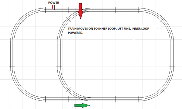
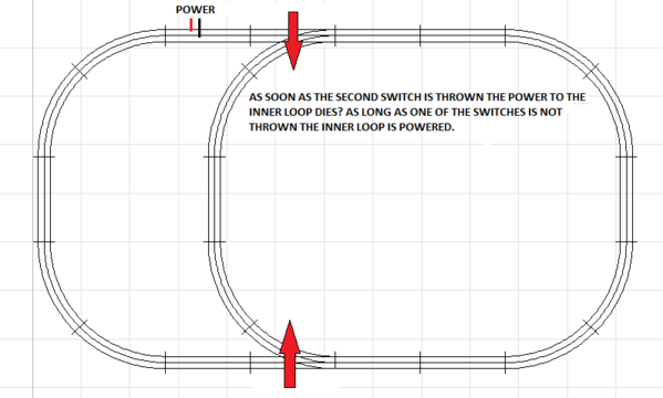
Hey guys, I set up a simple oval with two manual switches as shown in the pics.


When both switches point out, the train runs the outer oval fine. When any ONE switch points in, the train enters the inner loop and proceeds. If the other switch is set to point in then the inner loop dies...? I have a power lockon as shown. Do you suppose I need another power tap on the inner track or I am all wrong on how a basic manual switch works?


Thank you.


Ted


SW1

SW2

SW3

Attachments

Images (3)
  • SW1
  • SW2
  • SW3
Original Post

Replies sorted oldest to newest

It would appear that the switches are not passing power thru them, so when both are in the turn position, there is no power to the right of your switches.


If you put a power drop in the loop somewhere to the right of your switches, all should be good.


You might want to consider putting a switch to feed power to the inside track or outside track so you could park a train on one while the other is being used.  Then put a power feed to the right of the switches to  provide power to the main loop all the time.


Ed

Hey Ted, you must be using the postwar 1022 manual switch: The ones with the red swivel arrow, with activation by a vertical throw lever. Just so you know, that is the only Lionel 027 switch made with that feature of shutting off track power to the curve turnoff by having the switch set to the straight position.


So the "problem" you are describing is actually a feature unique to that one model of Lionel 027 manual switches... which is actually a nice added feature that has some advantages.


If you don't like that feature on your main line, try some other Lionel 027 switches and use the 1022 for a siding, which could be handy when wishing to park one engine and run another one.

Last edited by brianel_k-lineguy

I don't believe so, but some engines and cars can make it through a 1022 and not an 1122 because of the switch motor on the remote switch.


Another neat thing you can do with a 1022 switch (or a 142 Super O manual switch) is hook a 153 block signal up to each center rail of the two routes of the switch (with the common of the signal hooked to the outer rail) and it will show the position of the switch. I don't think this will work the way you have the power feed though, and if you have one switch in each position, both lights will be lit on the signal (which might be a neat safety feature...) But if you move the power feed to the other side of the top switch, you can add a signal and it will indicate which route the train will go.


J White


Originally Posted by 027Ted:

Indeed they are the 1022 manual switches guys. Go figure. Thats alright, this is just a learning testbed.


I would assume that the 1122 remote switches don't suffer from this issue?


Thanks for the tips.


Ted

Ted:

FYI, attached is a scan of the 4-page Instruction Sheet for the #1022 switches.


Actually, as others have posted, that was a very useful feature built-in to those 1022’s. The post-war Super O #142 manual switches also had this feature but the “O” manual #O42’s did not. 


It’s particularly useful when used on a dead-end spur siding as it eliminates the need to run a separate feeder wire and toggle switch to the siding.  And no, the 1122’s do not have this “problem” but they do have motors with the built-in non-derailing feature. 


HTH,


Bill 


Attachments

Files (1)

Add Reply

Post

OGR Publishing, Inc., 1310 Eastside Centre Ct, Suite 6, Mountain Home, AR 72653
800-980-OGRR (6477)
www.ogaugerr.com

×
×
×
×
Link copied to your clipboard.
×
×