
I'll note here that everything is running... but there is always room for improvement.


First the pin #5 question:

I have read and seen on several occasions that the TMCC signal on a Legacy base can be improved by "grounding" pin #5.

1.  I have the original TMCC Trainmaster base and not a Legacy.  Is this still applicable for the original bases?

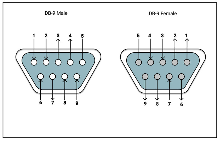
2.  If it is, which one is "pin #5" on a TM base?

3.  From the posts, it is not crystal clear as to what and how I am grounding that pin.  Do I just stick an appropriate gauge wire in there and run it to what... 

the ground of the house (I have field antennas set up using the grounding lug on my home outlets)?  OR some other "ground?


On the Z4000 voltage "float":

As some of you may know I am constructing a larger layout (30X50 double decked).  I have this sectioned off and running it with two Z4000.  These two are grounded together and in phase (lets call the throttles 1A, 2A, and 1B , 2B).  ONLY on transformer B, when I move from one section to the next (so a train moving from throttle 1B to the 2B) on the same transformer, the voltage will leave the 18 volt setting and float.  One generally goes to 20-22 while the other goes to about 15-16.  I say "float" but not really.  Once they move to those voltages they stay there unless I change them.  I adjust these back to 18 and it holds again until the train crosses back, requiring me to again adjust the throttles to 18 volts.  

Oddly, this does not happen when a train moves from transformer A to B.  Only between 1B and 2B.  I swapped out for a different Z4000 but get the same results.  It must be track and wiring but I can't come up with how, where and why.

Thanks to all!


Original Post

Replies sorted oldest to newest

As for the pin 5 might wait tell someone else also posts but as long as pin 5 is the correct one cause I’m not sure I’d have to search the forum you just need to search for a 9 pin serial pin out and it’ll show how those pins are numbered. Take the wire to the best Earth ground (house ground) you can get to. 

the “voltage float” in surprised it’s not on both transformers But I suspect that when you set a given channel it’s either with a load or without but when the load moves from one to another the channel that had no load now has a load and the transformer is power settings it’s not going to be like Cruise control and keep the same voltage. As the load increases the voltage will drop. On the other channel as the load leaves it has more available power so the voltage will rise. I don’t know if there’s anything that causes this to be more profound in a one Z4000 to another other people are more knowledgeable on that transformer than I 

Here is a pinout that shows the location of pin #5:

DB-9 pinouts

That pin is connected to your house earth ground wiring via the third prong of the Command Base power cord.

To improve TMCC signal in weak areas (typically areas of dense tracks or where tracks cross over each other), you connect a wire (any gauge) to pin 5 and route around the problem area.  Precise geometry is probably not important; you can experiment to see what works best.

If you have large areas of metal around the layout that are interfering with signal (wire mesh; bridges) you can connect the earth ground wire to that metal to improve signal.  Do not connect the earth ground wire to layout common (outside rail)!

Gun, what do they run$? (I have to be a little careful, after 36 years with the same company, it looks like they are going to be "releasing" me soon).  As I said, the layout is running well, but there is always room for improvement.  What will the unit do for the layout?  The ground field antenna(s) have certainly improved things.

Thanks!

Add Reply

Post

OGR Publishing, Inc., 1310 Eastside Centre Ct, Suite 6, Mountain Home, AR 72653
800-980-OGRR (6477)
www.ogaugerr.com

×
×
×
×
Link copied to your clipboard.
×
×