Operation of the RailKing #30-11009 Cantilevered Signal Bridge


This accessory is typical of cantilevered style signal bridges.  It uses colored signals for signalling a proceed, caution or stop condition. 


O Scale Cantilevered Signal Bridge

Product Number: 30-11009

M.S.R.P. $ 59.95

First appeared in: 1999 Volume 2 - Berkshire


Prototype Signals:

Color-light signals came into use around 1914. Three different colors are provided for signalling.Green (proceed), yellow (caution) and red (restricted). 


The signal as shown has the red lamp above the amber lamp.  This is the same arrangement as used for "traffic" lights.


RailKing signal wiring:

Black wire is common.

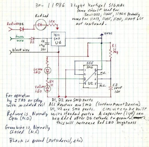
Green is wired to a normally closed contact. (10 to 18 volts) When powered the yellow lamp is on.  After 10 seconds the green lamp is on.

Red is wired to a normally open contact. (10 to 18 volts) When powered the red lamp is on


30-11009

catelever signal bridge prototype

Chessie_DK_ColorLight [1)

atlas rk mth 001

atlas rk mth 002

atlas rk mth 003

Attachments

Images (6)
  • 30-11009
  • catelever signal bridge prototype
  • Chessie_DK_ColorLight (1)
  • signal bridge 1
  • signal bridge 2
  • signal bridge 3
Last edited by pro hobby
Original Post

Replies sorted oldest to newest

pro hobby posted:

Operation of the RailKing #30-11009 Cantilevered Signal Bridge


This accessory is typical of cantilevered style signal bridges.  It uses colored signals for signalling a proceed, caution or stop condition. 


O Scale Cantilevered Signal Bridge

Product Number: 30-11009

M.S.R.P. $ 59.95

First appeared in: 1999 Volume 2 - Berkshire


Prototype Signals:

Color-light signals came into use around 1914. Three different colors are provided for signalling.Green (proceed), yellow (caution) and red (restricted). 


The signal as shown has the red lamp above the amber lamp.  This is the same arrangement as used for "traffic" lights.


RailKing signal wiring:

Black wire is common.

Green is wired to a normally closed contact. (10 to 18 volts) When powered the yellow lamp is on.  After 10 seconds the green lamp is on.

Red is wired to a normally open contact. (10 to 18 volts) When powered the red lamp is on


30-11009

catelever signal bridge prototype

Chessie_DK_ColorLight [1)

atlas rk mth 001

atlas rk mth 002

atlas rk mth 003

This is a question on the wiring.  The black wiring goes to the transformer common.  The green and red wires go to the "hot" side of the transformer.  Red wire illuminates the red LED.  Green wire illuminates the green LED.  Is this correct ?

Brain Teaser:  Supply 15 VAC, black common, Green hot.  At initial power-on green light is on and yellow light off, draw 55 ma.  After 10 seconds green light is still on and yellow light is still off, draw 110 ma. Add second head on the opposite side of first head.  At initial power-on both green and both yellow lights on, draw 40 ma.  After 10 seconds both yellow lights turn off, draw 80 ma.  Draws are approximate.  What's wrong ?

Last edited by shorling

It appears that the "timer" portion of the circuit is operating for both signal heads.  That's good news.

Since current draw is greater when one LED is on (i.e., lower when BOTH LEDs on), I'd say you have some kind of wiring short.

Perhaps you can confirm, for the record, that the dual signal head is simply 2 circuit boards of the type posted earlier.  If so, and you are handy with a voltmeter, measure the voltage at pin 3 of the 555 8-pin timer chip.  With a DC meter's black (-) lead connected to the circuit ground (black wire going into each circuit board), pin 3 should swing from ~12V when Yellow should be on, then drop to near 0V when Green should be on.


Add Reply

Post

OGR Publishing, Inc., 1310 Eastside Centre Ct, Suite 6, Mountain Home, AR 72653
800-980-OGRR (6477)
www.ogaugerr.com

×
×
×
×
Link copied to your clipboard.
×
×