
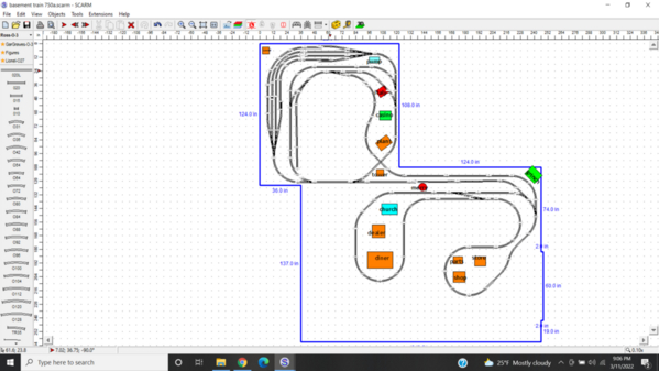
I have started a new post because after over a year of working on track plans, I am finally close to a final plan and after listening to other posters, I have given my plan a name.  I have decided to call my layout the Paint Creek Railroad and I'm down to one of there plans.  Attached are the three plans so please let me know which one you think is the one to run with.  Thank you in advance.


Attachments

Images (3)
  • mceclip0
  • mceclip1
  • mceclip2
Original Post

Replies sorted oldest to newest

I think it is a correct assessment to say I'm a looper.  I have a special needs son and watching trains go around with some switching is what he likes.  I originally liked number 3 the best because it allowed the most track for the yard, but once I look at it closer, I see that it will be very tough to reach the far corner.  Even though number 2 reduces the yard space, it may be the most practical for us.  When I had my old layout, he really liked the drawbridge so that is very important to me and it is incorporated in all 3 plans.  I can do some tweaking to number 2 as I still have still to paint the room, add some lighting, and run some additional electrical before I even begin the benchwork.   Thank you for the replies and in regard to Jan's post, I don't understand your comment to place the "staging yard" below the main level of the layout and move the visible portion over top.  Please elaborate.

The left portion of the layout will be two levels with the staging tracks being on the lower level.  The track to the lower level will need to descend to the staging tracks.  The tracks to the upper level will need to climb.  You have 10 feet to get the necessary clearance between levels.  Eight inches between level tops (remember that there will be supporting structure, etc.)  will give you a 3.3% grade.  If you can start either grade sooner will be better.

The layout will have three different table heights.  Two, highest and lower, on the left and middle level on the far, far right.

If you post your SCARM files you'll likely get more suggestions and help.

Jan

Vitto, since you are in the planning stages I would suggest that you give some consideration to a backdrop for the walls. At the very least go with a shade of sky blue. On my walls I used Sherwin-Williams “cloudless “. Not knowing how old your son is I would contemplate his continued involvement as he gets older. As a retired special education teacher, I’m always about having the student involved.

I made a few changes to the yard and put in some elevation but I didn't know how to make the left part of the layout two levels as Jan described.  I really like the idea of three different heights so I'll need some help.  I attached the scarm file.  Also, my son is going to be 22 in a few weeks and he is excited about the new layout.  Thank you for the feedback.

Attachments

Vito - BMP will almost always be too big to post. Save as JPEGs. 

You have a couple of mis-aligned tracks - try running the train simulator - it will stop where there are disconnects. One is a result of mis-matched track heights.  A second one I cannot tell.  You also need to raise and lower the track where they cross. There is only 2 1/4 inch height difference.  I think you are going to have the raise one track and lower the other to get enough clearance.  That will give you an idea of the grades you can expect.

I prefer what you did with the new yard entry, keeping two long spurs, and still an entry and exit.

For your buildings - the new Menards theater and the barber shop look decent for under $100 fully lighted. WS also has new ones as well which are also nice.

Wow Jan, I really like what you did but I have a couple of questions.  I have an old lionel drawbridge (6-2317) that my father bought for me as a child and this is a must have in the layout.  I see a 90 degree crossing in the blue layer but I don't see how I could incorporate the drawbridge into the plan unless I raise the green and layers another 2.5 inches as that is the height of the drawbridge.  Also, I take it that the access to the red and blue layers will be a lift bridge with two tracks going across which shouldn't be too big of a deal.  Thanks for doing that.

The RED layer is the staging and at 0".  The BLUE layer is the upper layer and is at an elevation of 8+".  The GREEN layer is the lower level and has an elevation of 0" to 2" (where it connects to GRADE).  SCARM doesn't automatically draw the layers in the proper vertical order; RED is under BLUE.  Grades are roughly 3%.

The BLUE track uses only O54 curves but you could substitute O42.  Also the STAGING is O54.

Had to I watched a video to understand what you wanting to do with your drawbridge.   You can put the bridge where the YELLOW and BLUE lines meet where I placed a 90 deg crossing.  There is a complete loop on top that won't cross over the bridge; just go under it.

A swing-out gate supporting both the RED and Blue tracks will provide entry to the inside.  These have been discussed on the Forum.

Jan

I definitely want to build the layout designed by Jan but I am a little worried that it is being my capabilities.  Maybe this is a question more for the electrical forum, but I'll ask here.  I have one 20 amp breaker in my panel that I can dedicate to the train but will that be enough?  I also have a Z-4000, a TIU and some power units that come with the MTH starter kits but I have no idea if that is enough for this size layout. 

@Vitto  size of the layout has little to do with the power required to run trains. Modern engines draw about an amp. Considering what you have said you want to do,  a Z4000 is plenty big. What starts getting into trouble are lots incandescent lights (in passenger cars and accessories), multiple engines in a lash-up and anything else that draws continuous power. The other consideration is how you run power feeds to the track sections. Gauge of wire and length of run makes a difference as the power draw increases. Some prefer 16, 14 gauge or 12 gauge copper solid or stranded and then there are buss or home run/star feeder designs.  If you are running DCS pick up a copy of the DCS companion. It will help head off wiring problems and signal strength issues if you follow Barry's instructions. He describes power districts and blocks and recommends home run wiring due to the way DCS provides the control signal. In my little layout, each loop has a separate power block. Each arm of the Z will provide up to 10 amps for 20 total. 

For what its worth, I power only switches from the Z.  Everything else has separate power supplies. I've stripped out regular incandescent bulbs from all my buildings, so everything is either 4.5 or 12 volt DC  LEDs.   

I do have Barry's book and on my old layout, I used the home run wiring with I think what was the magic lights.  My terminology is not good but I think used what was called bricks to power my switches and a couple of building with lights.  Everything was good until I moved and got out of the hobby for over 7 years.  I just remember the wiring being a nightmare for me and now I'm looking at doing a bigger layout.  I know it can be done with all of the help available here on the forum but it's going to be a challenge.  Thanks for all of the help.

I've looked at the track plan designed by Jan and put in the drawbridge but the problem that I see is that the grade will be to steep on the top yellow grade.  The upper part of the drawbridge is 2.5 inches higher than the lower part so the grade going from blue to green has to drop about 9 inches and from my calculation, it puts that grade at well over 4%.   I could lower the blue tracks but then might limit access to the staging area below.  Am I looking at this the correct way?

Add Reply

Post
The Track Planning and Layout Design Forum is sponsored by

AN OGR FORUM CHARTER SPONSOR

OGR Publishing, Inc., 1310 Eastside Centre Ct, Suite 6, Mountain Home, AR 72653
800-980-OGRR (6477)
www.ogaugerr.com

×
×
×
×
Link copied to your clipboard.
×
×