
A couple years back I purchased a partially assembled GG-1 "House of Duddy" kit from a seller on Ebay. I'm looking for a source for scale Pantographs to purchase, even partial assemblies would work. I'm also toying with the idea of making them myself but I don't have the drawings or locate any sources for drawings, prints, etc. If anyone can help me out, I'de appreciate it. Thanks much, Steve

Original Post

Replies sorted oldest to newest

Thanks Tom Tee, I'll give Precision a call to see if they're still available. After some searching,  I found a post in Model Railroading about PSC's Pantograph, a GG1 PRR with insulators, and painted black. It was offered in PSC's Catalog No. 4 but the post was from 2006. Maybe they have one or two kicking around or parts to make one! Steve

as for scale or close to scale anyway I would look at Williams as another source if you can get paragraphs from there scale GG1 ( yes I know eww it's a Williams) but hey it just might be what you need as I know on there scale GG1 it goes from just shy of the windshield to just shy of the tip of the nose ( about 3'8" each end) now the question is as in size how close is a Williams scale GG1 is actually to scale. 

In length over semi scale, I believe they, and just about everyone else did make a "scale" GG-1. Overall accuracy? Thats another question to answer in full, but I don't think anyone reused the semi scale pants on them, so if exact scale is your game, try some review threads on them from Lionel, Williams, MTH. Etc. There was almost always a side by side comparison of them as folks decided which was "best". Keep in mind while pricing or deciding how to fasten them, some of these are motor operated and raise and lower by remote also.

The Bachmann, Mth, and others look close to each other if they have the silver wipers on top. If you look at the Mth Proto 2 and Lionel scale GG1 they have better looking pans, their wipers aren't shiny. I had mentioned before if you cant get them or the price is too high what I did on my MTH proto 1's is use gun bluing and it made the wipers dark so they didn't look cheap. Oh I forgot to mention I had call Midge about 5 years ago at MTH and said that there was different sizes at the base on some of the pans and you may want to check on the wipers because some of the GG1's had single wipers and some had double wipers. It depends on the road number but hey When the Pennsylvania needed a pantograph they used what they had. I have seen in pictures where same loco at differ points in time had differ pans.


Sorry for not posting anything the last couple of weeks, I was away in NC Fly Fishing, at least that's what I call it.  

Again thank you all for your suggestions.

MWB, good question. I'm not sure what the spacing is going to be once I figure out everything but will probably be close to the pad locations depicted in the pictures below. I purchased a single cast GG1 shell on Ebay about a month or so ago. At the time I was looking for a smooth shell to use with a House of Duddy frame assembly and drive as I already had a scratch built GG1 body modeled after old rivets, 4800.  The listing seller had no idea who had manufactured the shell so I took a chance and purchased it. From the pictures posted on eBay, the shell appeared to be cast in bronze. I had purchased an Alco PA that was similar in color and cast roughness which finished very nicely after a lot of sanding so I went for it.

 8

5

So with a little time and patience, I'm slowly getting a pretty decent shine on the shell.IMG_3433IMG_3435

The shell is 19" long, and appears to be cast in copper. The hue is different from what I remember working on the Alco PA.  After a bit of checking on the net, I found a video which showed a GG1, 2 rail which had been modeled by Baldwin?!?! I searched further and found a link to a UK archive which listed Baldwin as making a GG1 model cast in bronze but they didn't have a lot of detail on the model itself.  Originally I thought the shell I purchased from eBay was a cast offering from The House of Duddy but it appears it may not be.  So the shell appears to be modeled on O scale, 1:48 or close to it. A 79' 6" GG1 would scale to 19.88".  So with the frame extending a bit past the shell and couplers, I'm in the ball park.

I ended up contacting Fine Art Models who scaled a GG1 to 1:32 and asked if they would sell me one of their pantographs, I knew it would be a long shot but what the hey!!! Well as it turns out they were very nice and were willing to sell me one.  Though it's a different scale, I'm planning to scratch build my own and rescale to 1:48 using their Panto as the model.  I've spent more than enough time on their website ooogling over their models, and they are awesome, the detail is incredible.

So does anyone have info on a GG1 Baldwin?

Sorry about the last two pictures orientation. I couldn't figure out how to rotate them.


Attachments

Images (4)
  • 8
  • 5
  • IMG_3433
  • IMG_3435

I have to agree with you RoyBoy. I like the shiny brass look myself. I spent some time on the body today using a cutting and buffing wheel.  Getting there!!!!

IMG_3436IMG_3438

Still can't figure out what I'm doing wrong with picture orientation.  I had to rotate the first picture from the camera in order to get it to view at the right angle but when I import the picture into the forum it reverts back to its original orientation.

Attachments

Images (3)
  • IMG_3436
  • IMG_3438
  • IMG_3436 1

Steve-- FWIW... In my engineering involvement with PRR/PC/Amtrak the lowest wire I encountered on a running track on the main line NJ to DC was 17'-0" just a bit south of Baltimore Union Station, on 1 of 4 tracks.  (Of course the wire in the Hudson tunnels was lower still.)  North of the auto assembly plant, again Baltimore, the wire height had to at least clear the auto carrier car heights of that era.  I think these cars were then 18'-2" high; to this the electrical clearance of 9" was added, so that 19'-0" would have been a nominal minimum to the north from here.  There is at least one overbridge in this area with the wire at this height with the insulators then directly attached the outermost girders of the bridge.

I mention these examples because I think it might be difficult to make a scale pantograph operational at the lower range of the prototype.  But it is worth noting that the postwar Lionel GG-1 generally was thought to run best with a 5-1/4" wire height.  This model had a scale height and width, while its length was compressed to 70% of scale length (at quarter-inch scale); thus a 21' [*not 17'] wire height was optimal for it.

As your model will have longer arms on the pantograph, that may increase the optimal wire height.  As a guide, the coming of the high speed trains (Metroliners first) led to a desired wire height of 22', and generally to avoid supports from vehicular overbridges (essential with the Acela at speed).  As to maximum height, the electrified stubs into the many set-out yards along the main used a "high" wire, for safety, which was at 26' feet.

I am familiar with the scale models (semi-scale in wheel details, of course) by Williams, MTH, and Lionel, offered to their fans in that order over a number of years.  IMO, the Lionel model's shell is exactly to 1/4" scale... IIRC the dimensions were taken from a prototype in the Pennsylvania Railroad Museum by Lionel.  The Wms & MTH shells were a foot or so, not over two, shorter, perhaps to make the length between pulling faces of couplers to scale (all had tinplate knuckle couplers).  As for height over rail, the Lionel is correct; I do not recall checking this on the other two.

The Wms & MTH pantograghs are sprung and can be run against wire; the Wms can easily be electrified to run from the wire; this may be rather more complex with MTH due DCS.  The scale Lionel is quite complex just to get the (powered) pantographs to stop just clear of an intermediate height of 21' [*not 17'] (5'-1/4" wire to also accommodate the Lionel postwar GG-1).  It actually can be done by cutting power during the sequence and then putting the pantograph switch to "off" (you get 1 up).  I don't recall checking the max height of any of these three, except to say that the scale Lionel goes somewhere in the main line running range, and not to 26'; the others have stops to give a similar appearance.

I am not certain how Duddy handled this situation, except that he custom-made certain features of the furnished kits per questions he asked the customer.  Also, I do not know the history Alexander to Duddy.  You may want to satisfy yourself as to the scale of the brass shell which you have, whether !/4" or instead 17/64" (Q-scale), or since it may be of British origin, even their oversize O (7mm is it?).  The Lionel scale shell is best for this comparison.  By the way, the bottom of the cab shell was 5'-0" off the rail in the prototype, to the nearest inch, IIRC  (I knew this from my work, but there is a confirming source on the internet somewhere).  There is also the shell having an inward taper on the sides as it goes up, except that the bottom 8" or so is vertical where it overlaps the poured concrete floor.  I assume the top of this floor is at 5'-8" over rail, as this is the height of the engine's center of gravity.  Other dimensions are in the literature; the Lionel scale models has fairly accurate axle locations.

One thing to note is that the three scale models mentioned have the cab supported on pivot points controlled by the axis of the motors over the power trucks convenient for the gearing.  These points are rather farther toward the center of the car than the prototype, causing the pantograph to swing quite wide on curves.  In the prototype, the cab supports were farther out on the subframes guided by the pilot trucks, and there was little swing.  I do not know how Duffy handled this, but I'd say he thought about it.

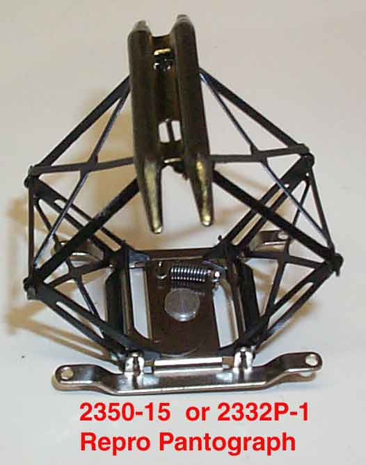
I also have the pantograph width dimensions over the horns, the length and drop of the horns, but I can't recall them and am not exactly sure where my sketch is.  I don't recall there being an on-line source for it.  They aren't as wide as one might think, although the models might be accurate here.

--Frank  *[corrected 17' to be 21' as the scale wire height at 5-1/4" over rail, 7:30pm 11/14]

Last edited by F Maguire

Hi Frank, thanks for the great information on the differences of scale on the various vendors, and the operational heights of the PANS vs. wire height between the GG1 in operation, and the scale/semi scale models you mentioned. Looks like I have some homework to do!! 

With the scale models, do the pantograph have a set operational height or do they ride sprung applying pressure on the overhead wire? You mentioned Lionel's system as being complex, I eventually would like to run power through the Pantographs but I haven't gotten that far into the thought process. I'm sure there are several variations on a theme. In you opinion what appears to offer the best performance with minimal trade-off for scale detail and accuracy. 

I had seen that Lionel shell. I dont know if the pantograph is a Lionel scale or a brass one. I too like the scale looking stuff. If you can get pantographs from Lionel Joshua Cohen scale  GG1 or the MTH Scale proto 2 version you will be happy. I know that there are different measurements on the MTH pantographs because I spoke to Midge at MTH and she told me this. Another thing some GG1's had single wipers like the 4935 loco. I would call Midge at MTH parts and she will help you out. She is the best and always helped me with parts. Another great person I worked with is George AKA G on here and he did work for me on some trains. MTH proto 1 and Proto 3 along with Lionel non scale K line and Williams have the shiny double wiper on top and to me doesn't look good so I used gun bluing on the wipers and they look better to me.

Steve last year for Christmas I put the MTH Catenary up on the dining room table using extra strong double sided tape. I also used 31 Radius track so it was tight. The problem I had was I could only use a Railking or Lionel GG1 loco under the wipers. The problem here was the wipers aren't that wide and they may get stuck in overhead wires do to the swing in turn of the loco. It took a long time to set up. 

I've been slowly working on the GG1, and a couple of days ago I received the pantographs from Scale Rail, thanks Don!!! These are just what I was looking for and they fit the shell perfectly, scale wise.

Last couple of days I've been working on the GG1 body, and have the shell sanded to 2000 grit so far..... Lots of work but lots of fun. Mindful, tedious, focused work....there must be something wrong with me....I love it! There's a bunch of detail work on the shell I'm wanting to do and then the quandary and dilemma, what do I use as a reference source for detail and accuracy to scale.  I forgot I had a copy of Railroad Model Craftsman magazine from December 1975 which has an O scale drawing of GG1, 4935 which was drawn by Alan B. Chesley. It's an awesome reference.


IMG_3463

IMG_3454IMG_3456IMG_3457

Attachments

Images (4)
  • IMG_3463
  • IMG_3454
  • IMG_3456
  • IMG_3457

Hi, Steve-- You'd asked for a recommendation; sorry for the delay... sometimes my time is not my own. 

Your three questions, in reverse order:  Which GG1 to power from the wire & operate is easy.  The early Williams, which operationally I think is very similar to postwar Lionel.  They may have gotten to use electronic reverse units by this time and also included a transformer-operated horn, but I'm not sure on either point.  But I do recall you wire it to take power from the overhead just like the postwar Lionel non-scale.  At one time, they became relatively inexpensive, so you could easily run two on a loop with one left on the 3d rail, without any further complication, except possibly finding two.   In this case, the pans are held against the wire by spring pressure or manually latched down.  The motors would be can motors, or possibly Pittman as some of their top-line engines had in that era; the operation was conventional.  WBB has also just now re-released a GG1, pictured as having two sets of electronics, probably motor and sound control.  The cost is up a bit; I am totally unfamiliar with how operation from the wire  with these would go.

As a footnote, if you wanted to operate more than two on a loop, again against the wire, you'd want to consider the MTH scale model, which had DCS 2.0.  The pantographs are scale (not sure if exact scale but look good, and IIRC similar to the Williams).  Mechanically they can be operated against the wire; I'm not sure that powering them from the wire if one side of the DCS was on both the wire and the 3d rail is practical if the layout is at all large.  The risk of signal distortion would be increased, for complex reasons.  The lengths of both MTH and Williams are about the same, as described in post above.

Second question:  For the mentioned Williams and MTH  scale models, spring pressure holds the pantographs against the wire.

First question:  For the first Lionels, when working off TMCC, the pantographs alternate with direction so that the rear one is up.  This action is power driven between normally only two rest positions: fully down and its maximum height, which I don't recall, except it is higher than the inside of a usual Lionel plastic display case.  If run in conventional, IIRC the pantographs remain as last set by TMCC.  There are control switches on top the engine so that each pantograph can be isolated from the effect of TMCC.  Because of this, with a great deal of patience, I was able to stop one of the pantographs apparently in contact with the roof of  its case.  Their range of motion, in this intermediate position, was about 1/8" under slight spring pressure.  With this arrangement, one could operate from the wire, from one specific pantograph of the two disconnected from its factory arrangement *as a TMCC antenna.  That would depend on the other being down, and in that position close to the metal shell, still able to develop sufficient signal power.  Care in the wire height is also required, as plus/minus about 1/32" would be required; this would also require patience but I think this would be possible.  Unclear if spring pressure would be enough for drawing enough current.  Operation from forward pantograph was unusual but seen at times.  Operation would have to be conventional.  (*I think I am correct in remembering that isolated cab ladders were used as TMCC antennas only on the smaller GG1s, and not carried forward to the scale GG1s.)

Otherwise,  a wire height about !/8" above the max pantograph could be chosen, and the full range of TMCC operation enjoyed.  That there was no contact would probably not be noticeable.  Disadvantage here is not having the customary lower wire height.  At the time there was discussion about modifying the raise/lower mechanism, by various users.  IIRC, no replacements available in any case.

I think a 2-track "corridor" oval at 4-3/8" track centers (4-1/2" on curve) and one interlocking is barely practical, using O-72 (outer track hand bent slightly) and normal wire height.  That's my thinking to date.  This will permit use of the signal bridge at any point and most 21" passenger cars.  Never quite sure of course; there is no room for error with everything this close.  This size is a lot of work.  Hope this helps.

--Frank

You had written:

Hi Frank, thanks for the great information on the differences of scale on the various vendors, and the operational heights of the PANS vs. wire height between the GG1 in operation, and the scale/semi scale models you mentioned. Looks like I have some homework to do!! 

With the scale models, do the pantograph have a set operational height or do they ride sprung applying pressure on the overhead wire? You mentioned Lionel's system as being complex, I eventually would like to run power through the Pantographs but I haven't gotten that far into the thought process. I'm sure there are several variations on a theme. In you opinion what appears to offer the best performance with minimal trade-off for scale detail and accuracy.

Check out the premiere MTH GG1 pantographs. Call Midge at MTH parts. The Premier line Proto 2 looks better it doesn't have the shiny wipers. The cost may even be $5 more.To me I just like the scale looking better. If I was using these pants, I would get gun bluing from a sporting goods store and use it on the wipers. You have to get any oil off and scuff up with 400 sand paper. If you ever seen a real G it doesn't have shiny or chrome looking wipers. Midge will help you out, she is the best. You just have to give her some time because they are so busy. What are you going to fabricate and use for the roof top and door coverings?

Thanks Frank that's great info!  

You had mentioned, "One thing to note is that the three scale models mentioned have the cab supported on pivot points controlled by the axis of the motors over the power trucks convenient for the gearing.  These points are rather farther toward the center of the car than the prototype, causing the pantograph to swing quite wide on curves.  In the prototype, the cab supports were farther out on the subframes guided by the pilot trucks, and there was little swing.  I do not know how Duffy handled this, but I'd say he thought about it."

I thought about what you said Frank, and you bring up a very valid issue with shell articulation "Pantographs growing through the curve" vs. truck swing and track radius. At some point I will need to secure the shell to the frame assembly and will certainly need to take into consideration what you mentioned. It looks as if the factory had bearing blocks over the Quill drive assemblies which in essence allowed the frame to somewhat float on the frame. You can make out the bearing blocks over each drive assembly, (that's what I call them) in the picture below.

download

I ran into an issue which I believe I have been able to see my way through as to the cause but need some help in getting the correct measurements to fix what I'm experiencing.  When I placed the wheel assemblies into the journals and attempted to place them into the side frames, the journals where very tight. I mentioned earlier I had an O scale drawing which is on a 1:48 scale.  I placed the frame assembly on the drawing and it matched up very close. I think the issue I'm having is with the axle width which is not prototypical to scale for a 4' 8.5" inner rail width but is on a 5'. Roughly the inside rails should be 1.177" for a 1:48 scale on 4' 8.5" standard gauge. Should the rail heads be equidistant on the wheel treads?  Does anyone have an idea on what the measured distance should be between the backsides of the wheels for a 4' 8.5" standard gauge?

Shurlock1, I'm going to use brass, any ideas?


Thanks everyone...

Attachments

Images (1)
  • download

All the wheel drawings are in the AAR Manual of Standrads and Recommeded Pratices, Section G "wheels and axles". Taking care of grand kids right now. I will try to post picture later. The gauging point is on the flange, 5/8" above the tread at a particular point, which is important since the tread is tapered. The gauge point is only used by design engineers since it wears away quickly in normal operation.   The back to back number is the number everyone in the wheel shop lives by. The 3/4" clearance between the flange and the rail is another design engineer number. Due to wear on both the wheel and rail this dimension can increase to two inches or more. 

@Steve-- The large steel plates, to which I believe you are referring as load bearing, are not.  These are spring-loaded to slide against the bottom of the cab floor, and serve to seal the air flow ducts cooling the 12 motors.  I think that the vertical load is taken to the subframe at the center pivots, in the usual manner.  Notice that the cab is on 4 stands at the ends of the two cross beams at these points.

I believe that you will find that these points are just a bit further outboard of the outermost drive axle at each end.  Or, about 4/9ths outboard along a line joining the center driving axle with the center of the pilot truck.  This is based on the pilot axles (2) each carrying 2/3d's the weight  carried by each of driving axles (3).  Actual weights are not so uniform and the actual calculation is more complex.  This depends also on installed equipment, particularly the steam boiler, but I think all the pivot points were the same.

I notice a loading pad on the nearest frame (in pix) outboard of the wheels.  Can't tell is this in a tipping roller or a flat loading pad of low-friction material.  It is inline with the center pin location as described above.

@Steve-- There is no lateral motion in any of the driving axles of a GG-1, including the center one.  Pennsy had their own standards and did not follow AREA (as it was then) standards.  In particular, the driving wheels were flat (IIRC), and ran in a tighter gauge of 4'-8 1/4" on tangent, with gauge widened on curve as necessary (see book written by a track foreman of Pennsy, found in Enoch Pratt Free Library Baltimore nearly 65 years ago; still there last time I was).

IIRC, Amtrak in fitting out Ivy City to service GG1s in their waning days, had two drop tables which could be used to remove GG1 driver wheelsets for wheel truing.  So profile wear on passenger power received a lot of attention.  Flat treads reduce impact in passing through open frogs.

In general-- I looked at the MTH pantographs.   They are against the inside top of the Lionel clear cases at a scale 21-feet over the rail head.  The interior angle between the lower and upper frame is about 45-degrees at this height.  I think the appearance would be slightly better at the high-speed height of 22 scale feet.  It appears these would reach the yard lead height of 26-feet without losing spring pressure against the wire, but I did not have time to take the case down and measure this.  On the Lionel, I have both pans set well below a less tall glass case, one at 18-feet with 30-degree internal angle and the other at 17-feet.  They look quite operational in holding the pans level.  Of course, the wire following is not possible for varying heights, although that height can be chosen.  But there is no need to worry about coming out from under the wire horizontally.

--Frank


Add Reply

Post

OGR Publishing, Inc., 1310 Eastside Centre Ct, Suite 6, Mountain Home, AR 72653
800-980-OGRR (6477)
www.ogaugerr.com

×
×
×
×
Link copied to your clipboard.
×
×