I have a large layout application (~160’ mainlines, with multiple trains on the same track with long grades) for a DCS tiu and I am thinking that operating in passive mode may be the right option. I have an early version of Barry’s DCS guide, and while he mentions passive mode and shows the wiring, there were no references to chokes or TVS diodes to be used.

There are several threads on here (and other places), discussing using a choke and TVS, but was not able to see a diagram on how others have  wired for it.  I initially would like the capability of at least 10 amps on the tracks to run passenger trains (incandescents) but also thinking of maybe wanting to use two 180 watt bricks in parallel , increasing to 20 amps on a single track.

I was looking at using the following choke to keep from loosing the DCS signal across the transformer connection.  I assume this is placed between the tiu and the transformer on one of the legs, correct?  Is there a reason I would pick one leg over the other.

https://www.digikey.com/en/pro...X1D2213L220/10441241

I was also looking at this TVS to be used across the negative and positive tiu output terminals for the specific track  to help prevent surge/voltage spike issues from derailments getting back into the TIU.  Figuring 20 volts rms (I maybe be using a z4000 as well) would produce normal peak voltages just below 30 volts.

https://www.digikey.com/en/pro...se-inc/SA30CA/688260

Is this the approach and components sizing others are using or is there better one?

Thanks!

Mike

Last edited by Hump Yard Mike
Original Post

Replies sorted oldest to newest

Put the choke in the hot leg- red terminal. The logic is that for TMCC/Legacy and other reasons you want outside rail as common or U throughout the layout. Putting the inductor in the U leg would not necessarily be the worst thing, but just to keep things straight and logical this is my reasoning.

Great post and diagrams here https://ogrforum.ogaugerr.com/...3#153603996468982503

The inductor is fine and that is what I used or very similar.

On the TVS, you linked a 500W rated part and I'm not sure on the trip voltage. I use 1500W rated parts and typically the 36 or 39 part number which were higher voltages. Here's the logic and reason why. You want the TVS o clamp spikes for sure, however, just normal operation of trains generates some spikes. We need the TVS to be able to handle and not clamp and be destroyed by common spikes generated every day, but the destructive higher spikes that could damage equipment need to be clamped. That's why both the wattage rating and specific part number clamp voltage range through experimentation by others of what gives you a safety net that should prevent damaging spikes in voltage, but not catch the minor spikes of normal operation and cause the TVS to fail and die early.

Think of it like a smoke alarm. If I goes off all the time- eventually you get mad and disable it. Then you have no protection. You need it to work when it needs to, but not go off all the time during normal events.


Now caveat, I was going off part numbers so again, we new that 33, 36, and 39, all the way to 51 were the common recommended TVS diode numbers- however the actual rating is not that exact number. Your part linked might be a different number system part and you chose clamp voltage and that value is correct.

I'm copying and pasting a blurb from a post I made previously:

I say all this from the perspective of replacing a PILE of TVS diodes in a stack of devices last week. Example was 3 Z controllers from MTH Z1000 sets, TIUs, and some other equipment. The interesting thing is the voltage values and the fact they STILL failed. Example, TIUs and Z controllers use the 1.5KE51CA in the variable voltage section, where the output of the TIU is a lower 1.5KE33CA, and then an often recommended TVS for transformers and track add ons is 1.5KE36CA
The point being, 33 is the lowest, and 51 is the highest, so I'm thinking if a 51 blows, that is one heck of a spike on the track. In the case of the 51s blown, the electronics were also damaged (FETs in the variable voltage circuit).
I'm just trying to give perspective here on why a TVS value is chosen. If the TVS value is too high, then spikes get through and can damage the electronics. If too low of the TVS voltage value is chosen, it does a great job of protecting electronics from voltage spikes, but may in turn fail more often due to catching more spikes from everyday events. Somewhere around the suggested value of the 1.5KE36 is a good value and proven by field testing and experience. Again, just trying to give perspective here and understanding. MTH TIUs have been using 33s internally, the variable channels have a 51 across the circuit as does the Z controller. By using externally 36s, I think we strike a value that should help protect the internal ones and provide a reasonable headroom for non damaging spikes on a given layout that don't kill TVS diodes too often.

Point being, I think in a previous discussion the recommended part now is

1.5KE39CA

https://www.digikey.com/en/pro...on/1-5KE39CA/7357041

Last edited by Vernon Barry
@Dave_C posted:

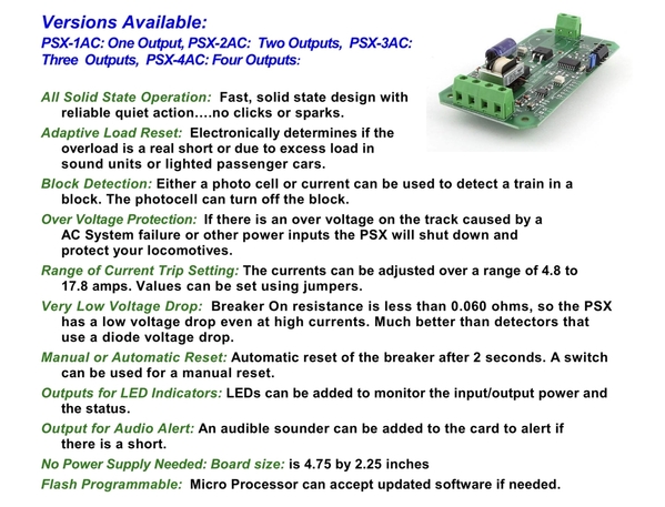
For circuit protection.  I’ve had these on my layout for years. No issues and they have got good reviews on the Forum. You mentioned 20 amps. These you can adjust to 4 different ratings with one being close to 18.

FD2077A3-8554-465B-A3E0-087BCAD6266A

Check out my videos on these.  Great devices.  I see no point in passive mode over wiring your power directly through the TIU.  If there's emergency and you need to kill power, hitting the red button on the DCS remote will do nothing.  Wiring it direct will ad another layer of protection.

I appreciate the feedback All

Vernon,

Thanks for the links.  The TVS you mentioned has similar Voltage properties as the one I selected, but I assume that bigger wattage ratting would help in handling a larger impulse of current with less damage to the device?  Great links as well.  I had not considered the DC off set from a whistle/Bell signal.  I also probable need to size a TVS specific for the Brick Voltage (18Volts) and then one for the Z4000 (i forgot, but thought this 20 Volts).

Dave,

I will need to spend some more time looking at protection device you recommend.  Do you run DCS using these breakers?

Gary.

I agree with what you are saying on not wanting to lose the red button feature on DCS, and I feel the same on my personal layout.  The layout I am referring to in this post is for friend of mine.  We are on our third TIU, where the FETs on variable channels seemed to develop degradation over a few months (lionel 180W bricks are powering them), the variable channels cannot be turned fully off, just down to 2-3 volts.  When it was new, it was verified it could be taken close to 0 Volts.   When I say this, this was measured with volt meter on the TIU output with the track connections removed.  I assume whatever is causing this, is also harming other aspects of the TIU.   I have to assume this is some sort of surge or wiring issue, I wish I better understood why this happening, where the need for scope on the power feed would probably be the only way to understand and help isolate.    His layout is huge and it uses multiple TIUs for several isolated power districts (but share a common ground) with a complex track plan where they interconnect.  It also has a block signal system that counts on using an isolate rail for ground detection along with hidden staging yards using isolated rails for powering LEDs using DC through the outside rails.  We are also using isolated rails for non-derailing on switch machines (I think there is over 50 DZ1000 Switch machines).   

The layout has been under construction for years and it is hard pinpoint issues on it as it grew faster than it was documented.  We are trying catch up on the documentation and in the mean while attempted to look for issues may that be causing this, but there always seems to be something new discovered.  Some of the items we have discovers on this journey recently include, intermittent terminal connections, transformer phasing issue, metal fillings bridging rails, WIUs with intermittent power plugs, TIUs with failed FETs, a large array of different types of passenger cars where they seem to short over switches, etc...   The cost and availability of new TIUs going forward is concerning if we keep encountering issues, as he would like to still use a rev L in the future for the DCS remote.  Thinking passive mode could help support us as we work through these issues.

Zachariah,

I looked at the TVS you recommended and the saturation current looked to be only rated for 8.5 Amps.  I wasn't sure how quickly this might degrade the DCS signal as the 8.5 amps is exceeded.  Is this still pretty effective on your set up when you are maxing out at 10 Amps channel?

Charlie,

Thanks for the link!

Mike, I bought one many years ago and have since added 3 more. I use the 12 amp setting. I have a Mainline Max transformer that features a 12 amp breaker. I can’t comment on how fast the breaker trips. It never has since I installed these. Never had any issues with TIU’s or engine boards. Previously I used the Radio Shack fast blow fuses. Your mentioning of running close to 20 amps caught my eye. I think when these were first produced the high setting was a little less and was bumped up to almost 18 in the later versions. Probably for situations like this.

I know you can divide your long mainline into power districts and use 2 breakers and chances are your 3 trains are usually not in the same district at the same time. I ran that way at first. Found out you better pay attention. Forget to throw a turnout and trip a breaker and you don’t notice the stopped train right away. Trains are still running on the one that didn’t. Next thing they are plowing into one another. I fully understand why you would want high amp capability and one breaker controlling the action.

I understand the reasoning for using passive mode. I found with the newer trains and LED lighting. There really isn’t a huge amp draw running trains. My own layout is basically a meandering single track run that appears to be double tracked. I can run 3 trains and I have grades with not a big draw. I find the biggest offender to be smoke units which I usually leave off. I understand though in a club type setting or modular show setup they can be a  must have.

.  We are on our third TIU, where the FETs on variable channels seemed to develop degradation over a few months (lionel 180W bricks are powering them), the variable channels cannot be turned fully off, just down to 2-3 volts.  When it was new, it was verified it could be taken close to 0 Volts.   When I say this, this was measured with volt meter on the TIU output with the track connections removed.  I assume whatever is causing this, is also harming other aspects of the TIU.   I have to assume this is some sort of surge or wiring issue, I wish I better understood why this happening, where the need for scope on the power feed would probably be the only way to understand and help isolate.   

FYI, there is an internal TVS diode across the FETs in the variable channels. When they fail from abuse and spikes, they leak current around the FETs and in complete shorted failure (a typical mode of TVS failing is shorted) then the output is "stuck" ON. So it could mean that is your problem.

You can clip one side lead of the TVS and then test or test the TVS diode with a meter (continuity/resistance).

I've circled and show the various TVS diodes, however the ones in Yellow are specific to the variable channel and Like I said, unlike the typical short circuit that happens when the output TVS in red fails, when the variable channel ones fail, they cause leakage or ON state of pass through power past the FETs.

The variable channel TVS (yellow) are 51s https://www.digikey.com/en/pro...inc/1-5KE51CA/688036

The red circled output ones are 33s https://www.digikey.com/en/pro...inc/1-5KE33CA/688026

Attachments

Images (1)
  • mceclip0

Also, I do not recommend this for anything other than bench testing. The TVS diodes are there to protect other components and are desired/needed when powering trains and track. But like I said for testing, a suspected damaged TIU where a variable channel is stuck on, or in your case, appears to be partially conducting even when fully off, then it's possible the TVS has failed or is dying and is the source of the voltage "leak". Obviously confirm this and ideally have a replacement TVS in stock on hand, but you can clip TVS diodes using good side cutters. The TIU can operate because again, these are in parallel portions of the circuits to protect other components. Because they are in parallel, opening the circuit can help you isolate the TVS diode and determine if they are in fact conducting when they should not be. This lets you determine which side is leaking, the FETs or the TVS.

And given they are under a $1, I just typically replace them even if I found during troubleshooting that was not the cause.

Just sharing my method.

I appreciate the feedback All.

Zachariah,

I looked at the TVS you recommended and the saturation current looked to be only rated for 8.5 Amps.  I wasn't sure how quickly this might degrade the DCS signal as the 8.5 amps is exceeded.  Is this still pretty effective on your set up when you are maxing out at 10 Amps channel?

Charlie,

Thanks for the link!

I have so far not ran into any issues with the lower saturation amperage but here is a similar one with a 14A saturation.

https://www.digikey.com/en/pro...2617BHA-220K/7695917


But like I said zero issues yet with my previous set up.

How do you know TVS specs/sizes used inside the TIU, has there been an MTH bulletin on these?  
Repairing them (TIUs) is one good way to get up close and personal. That said, anyone could pull the cover and read the codes stamped right on the components. All you have to do is own some MTH yourself, and then have friends who have MTH, and a soldering iron, with some electronic knowledge and experience, and you too will get wrapped into fixing a pile of these. Given the insane cost of used ones- there is good incentive on repairs.
Ones in Red are 33s from the factory.
Ones in Yellow specifically for variable channels (2 by the heatsinks) are 51s
Ones in the logic power supply section (labeled yellow) are 33s just like the output ones.

And yes, on the backside of the board, there was a bulletin (specific to revision "L") for even more TVS diodes specific to the DCS signal portion- under "featured topics" of the entire forum https://ogrforum.ogaugerr.com/...ion-service-bulletin

To my knowledge, I've not seen an official MTH how to fix TIUs or service bulletins. They were not in the training material and service documents I have access to. I think the folks who know more either had inside connections to MTH or worked at MTH?? I'm still kind of the new guy in town.

Attachments

Images (1)
  • mceclip0
Last edited by Vernon Barry

Add Reply

Post
The DCS Forum is sponsored by

OGR Publishing, Inc., 1310 Eastside Centre Ct, Suite 6, Mountain Home, AR 72653
800-980-OGRR (6477)
www.ogaugerr.com

×
×
×
×
Link copied to your clipboard.
×
×