With some layout changes, I find myself in need of a couple of PBWs. Let me know if anyone has built up or kits they are willing to sell.
Ken


|
|
With some layout changes, I find myself in need of a couple of PBWs. Let me know if anyone has built up or kits they are willing to sell.
Ken
Replies sorted oldest to newest
If you are talking about the DCS-RC Watchdog Generators I might be able to help you out in a couple of weeks. My email is in my profile.
rtr12 posted:If you are talking about the DCS-RC Watchdog Generators I might be able to help you out in a couple of weeks.
I've lost track of where "we" are on the PBW. Are you gathering raw boards and parts for GRJ's trimpot version?

Will these be assembled or just a kit with bare PCB and a bag of parts?
For reference, was the Bill-of-Materials (e.g., DigiKey parts list) posted for the trimpot version along with the OSHPark link for anyone to order boards? It's just that even if assembled boards are offered, the user must still solder the 3-pin square-pin header/socket to their DCSRC. I haven't checked but I'd think MTH might have discontinued the DCSRC (???) if they are offering the Explorer in "Starter" sets. So curious is anyone has considered offering a ready-to-go PBW that doesn't require soldering. ![]()
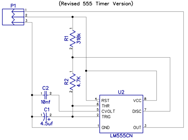
We were actually considering a 555 based version that requires no adjustment, PnP. It's probably what we should have done before, but better late than never. ![]()


Well. I'm all for PnP but doesn't this still require the user to solder the 3-pin header (or socket) to the DCSRC?
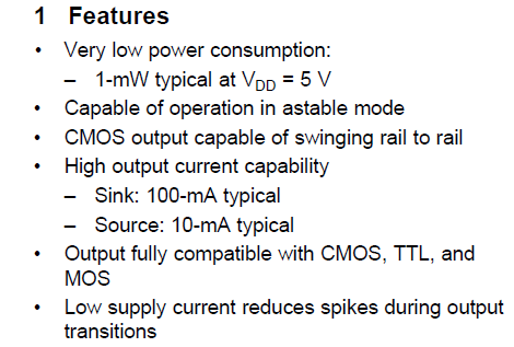
Also, one reason for using the 74HC14 (vs. 555) was the drastically lower current requirement since no information is available on how much power can be "stolen" from the DCSRC to power this add-on. I suppose one could use the CMOS LMC555 rather than the bi-polar LM555.
So that's why I was asking what the latest thinking is wrt the PBW. I'd have to hunt it down but I seem to recall an OGR thread where I suggested a $5 cycling timer-module that would perpetually cycle power to a stock (unmodified) DCSRC on for 1 sec, off for 0.1 sec which means the DCSRC would not need to be opened and modified at all. Problem was this was accompanied by relay clicking which could drive one nuts. I don't recall what happened but perhaps a ~$1 eBay SSR (solid-state-relay) module could be paired with some kind of timer-module for click-less operation.
Stan, soldering the header to the DCS-RC doesn't require calibration, but tweaking the pot does. The most questions I ever got were how to accurately adjust the pot without a counter or 'scope.
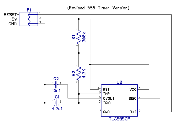
I was thinking of the TI CMOS TLC555CP version, it has very low power consumption, easily drives the reset line, and makes the package calibration-free. Quantity one from Digikey is 84 cents, so the price is reasonable. Exclusive of the PCB, the parts for this should only cost a couple of bucks from distribution, so the parts cost is not really an issue. I'd rather spend an extra buck on parts and have a board that can just be simply assembled and is ready to function.

Stan,
I had 2 extra PBWs that someone wanted. My originals from GRJ (the extras) went to the person in need. I wanted to keep one for backup, but was now sitting here with none left. Since I needed to make another one, I got with GRJ about offering some PBWs as kits, he was out of PCBs and parts. He brought up the 'no calibration needed' suggestion and went back to your idea from the original PBW thread mentioning the 555 timer idea and a PBW needing no calibration. I was using a different 555 here for testing, he mentioned your concern for too much power draw...and here we are. So far it is working pretty good on a breadboard (I ran my findings by GRJ and I think he was also satisfied).
I'm in the process of getting some PCBs and parts for these and was hoping to offer them as unassembled kits. I was going to try this with PCBs and parts for only 10 kits. They are the ones GRJ posted above with the 555 timer, no adjustments needed. The parts I ordered include the 3 pin header that still needs to be soldered to the DCS-RC board. I would prefer offering kits, but suppose I could offer assembled units for those that are really opposed to soldering, but as you say the 3 pin header would still need to be soldered.
As you point out with the Wifi Explorer, the DCS-RC has most likely been discontinued so demand could be quite low here. With that in mind I imagine there are probably still a ton of the DCS-RC sets out there in need of something to do. Perfect for conversion to PBWs.
I think the no soldering version you mention might also be worthwhile for those that do not want to even think about soldering something. If you could link me to the thread where this is described, I'll see about maybe putting together a few kits of that variety to offer along with the PBWs and see how it goes with those as well. Not sure if these are the proper type, but I have a couple of solid state relays around here somewhere. They are similar to the small ebay modules with the 10amp electro-mechanical relays that have become popular around here.
I'm not too good at designing this stuff, but I am becoming somewhat proficient as a shipping and receiving clerk. I also kinda like doing this stuff, makes me feel like I am occasionally helping out here and there. So, IMO, adding the 'no soldering required' kit would be a bonus.
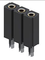
It would be cool if there was a 3-pin socket that would press into the PCB and make a secure connection. Hard to believe something like that doesn't exist, I just couldn't find one. ![]() If that were available, a truly "no solder" option would be available.
If that were available, a truly "no solder" option would be available.
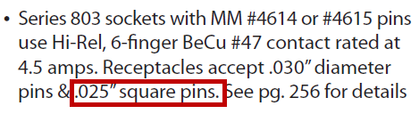
Actually, as it turns out, there is a press-in connector for .1" spacing. Mill-Max 801-43-003-61-001000. Not exactly cheap, but it does eliminate the soldering.

Pretty cool, that was a good find! But, I just put in an order at Digikey earlier today. Price wasn't all that bad, after all it is gold plated. ![]() I'll add a few to the next shopping cart, just to see what they are like. I probably forgot something so I'm sure another order will be needed to finish something.
I'll add a few to the next shopping cart, just to see what they are like. I probably forgot something so I'm sure another order will be needed to finish something.
I bet that price wouldn't deter someone that was opposed to soldering or would have to buy all the stuff to solder with for that one 3 pin header.
There may be others, I just found that one first in a search at Digikey. ![]()
I'll try looking around for more possibilities. I was looking at this in Digikey when adding to my new order and it is a 'Value Added Item' and went on to explain they make them up when ordered. Still indicated you could get same day shipping though. That's a new one on me. Interesting!
Let's see now, what else can I add to that order to make it worthwhile and hurry things up?
I didn't even notice that it was labeled as such, I never ordered a "value added item" before from them. Apparently, they chop a long strip of these up to make the size you order, interesting. I was just looking for the capability and the proper spacing.
I just did some more searching and there seem to only be 3 in a 3 pin configuration. Here's what I found. They show up as 'Press Fit, Solder'. Guess I'll look at the data sheet a little closer. They are staying on the order regardless, curiosity has the better of me now.
They had many more listed with different pin counts. Just change the search results from the link and they should show up, I think. It worked, just uncheck the box for 'Number of Positions'.
Did you confirm the finished (plated) holes on the DCSRC board itself are 0.040" per the socket spec?
Can this socket accept the 0.025" square-pin header? It looks like it wants round-pins - typically more expensive.
Stan, this is from the full spec sheet.

The DCSRC holes appear to be approx. 1mm as closely as I can see it with a MM ruler and my old eyes anyway. Pretty close to the 0.040". The pin headers I have on the bench right now are slightly smaller than 1mm, either square or slightly rectangular, as nearly as I can see. I don't have anything to actually measure the 0.025" with, but I think we may be in the ballpark.
Datasheet says 0.040" +/- 0.003 so perhaps OK. Do you have a numbered drill-bit set? #61 bit is 0.039, #60 bit is 0.040", #59 bit is 0.041". Looks like GRJ confirmed socket can accept the 0.025" square-pins you most likely have. Yes, if you're only offering a bag of parts requiring soldering then 93 cents for a press-fit socket may not be a good bang for the buck.
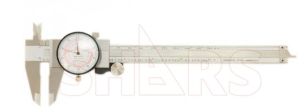
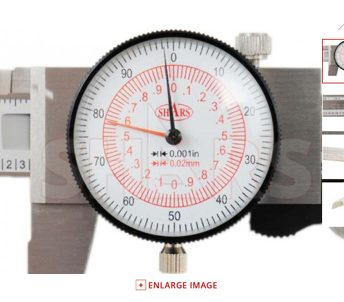
You need a good set of calipers. Here's what I use, very handy as they have both inch and mm readings. I got tired of the batteries always being dead in the digital ones, and went for these.
SHARS 6" 150mm Inch Metric Dual Reading Dial Caliper MM


stan2004 posted:Yes, if you're only offering a bag of parts requiring soldering then 93 cents for a press-fit socket may not be a good bang for the buck.
I was thinking more along the lines of assembled versions. The 555 board should be easy to assemble pretty quickly, and reach a wider audience.
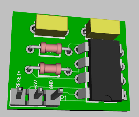
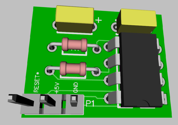
The two yellow caps on the 3-D rendering look to be non-polarized? The 4.5uF cap on schematic is shown polarized. 4.5uF is a somewhat unusual value - I assume this was just a placeholder value? Do you have the parts list - this would need to be a relatively tight tolerance part to keep the cycle time to 1.0 sec (+/-10%).
Hmm... I thought that was changed to 4.7uf. The real values are 4.7uf, 300K and 4.7k, that gives us a period of 1.008, probably close enough. The cap will likely be 5%, and the resistors can easily be 1%.
Couldn't find the footprint for the electrolytic, been using too many SMD parts lately. ![]() I fixed it the cheap way.
I fixed it the cheap way.


A #56 bit (smallest I could find) is slightly larger than the DCS-DC PCB holes. Found an old, cheap digital caliper (luckily the battery worked) which measured just over 0.040", very close to that looking through a microscope. The pin header I have is right at 0.025" and it fits with room to spare. Can even be rotated or pushed off in any direction at an angle while stuck in the hole, so there is some slop.
GRJ, I only found 10% caps in thru-hole so I got some extra resistors in various sizes. I was using an electrolytic that was probably at least 20% on the breadboard. It was a cheapie from a grab bag of assorted parts. Hopefully we will be close with these. Ther resistors were cheap too, 70-80 cents or so for 10 of them. Probably odd sizes, but I have very few 1% resistors here, mostly 5%. I need one of those mass quantity packs of 1% resistors from ebay.
Here are the parts I have on order so far.
296-1857-5-ND - TLC555CP - IC OSC SINGLE TIMER 2.1MHZ 8-DIP
399-14082-ND - C317C100K2G5TA - CAP CER 10PF 10% 200V C0G RADIAL
445-173369-1-ND - FG24X5R1H475KRT06 - CAP CER 4.7UF 50V X5R RADIAL
RNV14FAL300KCT-ND - RNV14FAL300K - RES MF HV .25W 300K OHM 1% AXIAL
RNF14FTD301KCT-ND - RNF14FTD301K - RES 301K OHM 1/4W 1% AXIAL RNF14FTD309KCT-ND - RNF14FTD309K - RES 309K OHM 1/4W 1% AXIAL
RNF14FTD274KCT-ND - RNF14FTD274K - RES 274K OHM 1/4W 1% AXIAL
280KXBK-ND - MFR-25FBF52-280K - RES 280K OHM 1/4W 1% AXIAL
287KXBK-ND - MFR-25FBF52-287K - RES 287K OHM 1/4W 1% AXIAL
294KXBK-ND - MFR-25FBF52-294K - RES 294K OHM 1/4W 1% AXIAL
316KXBK-ND - MFR-25FBF52-316K - RES 316K OHM 1/4W 1% AXIAL
324KXBK-ND - MFR-25FBF52-324K - RES 324K OHM 1/4W 1% AXIAL
And yes, I would only send the 'gold plated' 3 pin header with an assembled PBW, but I was thinking of also offering kits (which would have the regular old solder type pin header).
Hmmm...I don't see any PCB orders for these? Could have sworn someone had ordered those...Guess that someone better get on that.
The certain someone in question may have too many irons in his fire! ![]()
What's the 10pf cap for? 10nf is nano-farads, 10,000pf. ![]()
I couldn't readily find any 5% 4.7uf caps either, I guess they're pretty scarce.
Change up the values and use a .47uf cap, Kemet R82DC3470AA60J, 33 cents.
R1 becomes 3.0 meg and R2 becomes 47K. Both are available cheap in 1% resistors. This should get us close enough in frequency.
Xicon 270-3.0M-RC 3.0m 1%, 3.0meg 1/8w
Vishay RN55D4702FB14 1%, 3.0meg 1/8w

Thanks everyone for the continued work on this device. I have two RCs waiting to be modified. Like Tom, I suspect there are many unused units from early RTR sets where people have upgraded to full DCS to run multiple engines.
I'll stand by as the new design gets proofed out.
The new one "should" be a no-cal affair, just press the 3-pin connector into the DCS-RC, and plug in the board.
The pf must have been an Oops? ![]() I have 10nf on my schematic which is identical to yours above, that is what I was using for parts or trying to use anyway.
I have 10nf on my schematic which is identical to yours above, that is what I was using for parts or trying to use anyway.
I'll change things to the new parts you have listed above and give them the breadboard treatment when they arrive.
How about this for the 1% R2 47k: Xicon 270-47K-RC I think it's the same as the 3meg only in the 47k flavor. 22 cents for one, but only .021 cents for 10 (and 53 cents for 25). Didn't notice until I tried to order, but the other one is showing out of stock until Nov.
Also just ordered some PCBs from OSHPark using the 0.8 thickness and 2 oz. copper you were telling me about.
It'll work fine, any 1% 1/8w resistor is fine for the task.
I didn't notice they weren't stock, I normally work with Digikey, and they have an easier interface for searching than Mouser.
Ok, I have them in the cart ready to go. I am also more used to Digikey, but Mouser had some good prices on some of those resistors. Some had a massive price drop at Qty 10 instead of 100, like the 47k one.
I just found something interesting at JLCPCB. I was ordering some PCBs and fiddling around with quantities. It's 5 (up to 100mm x 100mm) for $2 and $5.24 shipping. So I tried 10, it went to $5 for 10 and $5.24 shipping, then I tried 15 and it went to $4.40 for 15 PCBs and $5.24 for shipping. Had to quit and didn't get to try 20, will have to do more checking on that later.
I've noticed some PCB houses have a "fixed" quantity they want to have you order and if you order more, the price for each one shoots up. So maybe there's a "knee" in the order curve somewhere where that will happen here. Once they're processing one board, it costs them very little to do a larger quantity.
That was an interesting discovery, hope it wasn't just a glitch and they continue to do that. Used to be 10 PCBs for $2, but they have now cut that to 5. I'll have to try that again, keep upping the quantities and see what happens. With my luck, I'll probably end up getting a great deal and ordering 50 with an error somewhere in the mix...
So what's a couple hundred bucks between friends? ![]()
![]()
A friend of mine keeps telling me "you can't take it with you when you go".
What am I going to do with all those trains??? I'm going to have to have a separate coffin buried with me with my trains. ![]()
![]()


I was hoping they had a nice electronics lab at my final destination, maybe I should also look into taking a few things along just in case. ![]()
And as a FYI, Mouser doesn't seem to ship as fast as Digikey. Ordered from both on Sun, got Digikey order yesterday, still waiting on Mouser order.
Yep, Digikey has the shipping skids well oiled, they ship in a flash. ![]()
Digikey is a finely tuned machine. I just got an email from USPS that the Mouser order has been delivered down at the mailbox. Guess it's time for an afternoon walk.
I got some of the Mill-Max 801-43-003-61-001000 in my Digikey order. They seem to be a pretty snug 'press fit' from what I can tell so far. Nifty little devices they have here, they appear to be well made.
My problem is I have 2 DCS-RC receivers, both with soldered pin headers from the first run of the PBWs. I was testing the 'press fit' version on some of the unused holes, a bit awkward. I was a bit reluctant to fully seat it in that position for fear of causing other problems, not being able to remove it after fully seated.
Also, I can't think of a good way to test the 'press fit' to be sure it's making good contact? Only being partially inserted in the holes is another problem with that. All I can think of is finding a generic perf board with identical holes for the test fit. I have some here somewhere, but it seems they had larger holes as I recall.
Any suggestions on how to proceed with testing these to be sure they will work correctly?
I "presume" that the other unused holes on the DCS-RC you have are the same size, try pressing a couple into those. If they press in with any kind of force, I'm sure they'll be making contact just fine.
Yes, correct, the unpopulated holes all look to be and measure the same, both rows of them. I was unable to fully seat the 3 pin header by hand, just barely got it started. It was harder than I thought from my first attempt at lining it up for fit. Ended up having to use a small pair of flat nosed pliers to fully seat it tightly in the holes. Just have to make sure the pliers clear bottom pins while pressing it through the PCB.
With a magnifying glass and a meter I was able to trace the 3 holes used for the pin header to their connected components and got good continuity on all three pins! Checked each pin a few times to be certain.
I was even able to remove the 3 pin 'press fit' header without damaging anything. Had to gently and very carefully pry it up with a small screw driver. As another test, I reseated it a second time (still needed pliers) and it all checked out the second time as well. These seem to work quite well, great find GRJ! Looks like we have a winner here!
That indicates you can actually have a "no solder" option if you assemble the boards. That should reach more people.
For pressing the header in, you might consider a small piece of wood with 3/8" hole drilled in it. Back the PCB with the wood, line the hole up with the three holes for the header, and use a vise to gently press the header in place. I would use my press, but if you don't have one, a vise works. Another method is using a drill press as a press.
That is becoming an option I'll be considering, these pin headers seem to work very well. And the reduced parts needed should be an advantage as well.
I'll look into the wood block suggestion. Sounds like a good idea there too.
You just have to insure whatever is on the bottom isn't pressed by the backing, which is why I mention a small block with just the hole for the connectors. With only six parts including the header, it would be pretty quick to assemble these boards. Give yourself a few bucks for the labor and make a little package that doesn't require any soldering to install in the DCS-RC.
From some of the stuff I've seen, a lot of people would love to be able to do something like this and not have to deal with soldering. ![]()
I think that's a good idea about the no solder PBWs, I agree that lots of folks just don't want to solder stuff and would like things that just plug in.
You were too quick replying, I was editing to add the following so I re-did it.
Need to do some testing with the new component values and check that out. I guess I'll have to rely on my Hz readings with the DMMs. The flashing LED is not synching extremely well with the second hand on my watch. It syncs for a while then gets out of step for a while. I don't have any PCBs yet so I can't try it on my layout until then.
I think that Hantek scope may be calling me here, that would be a good way to break it in. I have been eyeing it everyday at least once. ![]()
Once you have a decent digital 'scope for stuff like this, you'll wonder how you lived without it! ![]() If my ATTEN ever craps out, I'll be on the Internet ordering a new one. I'd probably go for a Rigol model, I've seen and heard good things about their products. However, currently the ATTEN is working just fine, and it's more than sufficient for what I do here.
If my ATTEN ever craps out, I'll be on the Internet ordering a new one. I'd probably go for a Rigol model, I've seen and heard good things about their products. However, currently the ATTEN is working just fine, and it's more than sufficient for what I do here. ![]()
FWIW, I test these with a little board with a socket and an LED, I just supply it 5V with a bench supply. I do have a frequency counter that I can hook up to check the period, but it's just easier to grab the 'scope, so that's what I normally do.
Or use the digital stopwatch function on your smartphone or traditional cellphone? "Start" on a blink, "stop" on the 10th blink. Should read 10.0 sec...+/- 1 sec if within 10%.
Good point about doing it for multiple resets, that does make it easier to time it without expensive equipment. Of course, for the design verification, I'd probably still want to know exactly what several samples do by actual measurement.
gunrunnerjohn posted:Good point about doing it for multiple resets, that does make it easier to time it without expensive equipment. Of course, for the design verification, I'd probably still want to know exactly what several samples do by actual measurement.
How is watching the LED blink not an actual measurement? ![]()
Stan, reaction time being what it is, it's an actual measurement colored by human reaction time. ![]() An actual measurement, at least to me in this case, implies a piece of test equipment.
An actual measurement, at least to me in this case, implies a piece of test equipment.
GRJ, I've heard good things about Rigol as well, very nice. I am still an apprentice and will probably have trouble using the Hantek. I saw something the other day about the Hantek 70Mhz model ($199) actually being the 200Mhz model and could be 'unlocked' with some kind of tweak or something? That was over my head, also sounded a bit questionable? Think I'll stick with the 100Mhz one we were recently looking at, the bait is working and very close to setting the hook.
I added an LED on the breadboard from pin 3 of the 555, what I was trying to time with my watch. I am not 100% confident the DMMs I have are measuring HZ as accurately as your frequency counter would? They do seem to be in the ballpark with the 555 calculator findings though.
Stan, all my watches are analog, I'm using Mickey's hands to do the synch test. I was trying to make use of one of the new fangled features (Hz) on some of the DMMs I have accumulated, all inexpensive of course. Good idea on the smartphone, hadn't thought of that. I'll give it a try with the LED and blink counting.
You guys are quick! As a friend of mine always says, "anything worth doing is worth over doing". I would like to test this in every way I can and will probably end up learning a thing or two in the process.
Hey, just thought I would bump this thread and see where we are at getting this mainstream. While I don't have any aversion to soldering I do like getting a complete kit to build and wanted to know if this will be offered in a completed version and one that can be a builders kit. I have built one already (thanks GRG) and due to recent changes to the layout need another. If you have un-powered yards this is the ticket to keep locos dark and silent when turning on those tracks.
I think Tom is polishing up the 555 based kit, that one will not require any calibration, just PnP.
GRJ is correct. New 555 design is working on a breadboard, but untested in actual service. I'm waiting on some PCBs to actually test it with a DCS-RC on my layout. With nothing unexpected happening, should have something ready in the next week or two.
The plan is to offer complete kits that will need assembly (soldering) and also a fully assembled unit that needs no soldering, fully PnP (thanks to the 'push-fit' pin header that GRJ found).
All the parts and PCBs are in. I have assembled a couple and been testing them on my layout that last couple of days and have had no problems so far. My initial order was mainly for testing to see how everything went, so far so good! I have a few already spoken for, but I still have several left (kit or assembled) from the first batch. The 'Press-Fit' headers seem to be performing very well here so the assembled version can now be a completely 'no soldering involved' version. Both versions are PnP (no adjustments needed) as mentioned earlier in the thread.
For anyone that is interested in one of these: Please send an email to my profile email address and I will email you the ordering information.
If anyone wants to make their own, attached are the revised Diptrace files and Gerber files for the newer version.

Schematic and Parts list are also included in the Instruction file (.PDF).
Edited - 05-08-2020: Fixed error with value of R1 on schematic and parts list. All related files posted here have been updated.

I am getting ready to assemble one of these and I have a question about the value of R1. The part number that is listed is for a 3.0 Mohm resistor, but the diagram shows a 300 Mohm resistor. Which value is correct?
Well, it's a 3.0mb resistor, if it were a 300mb resistor, you could just use air! ![]()
Thanks. That's what I thought, but just making sure.
Good catch there, I've been missing that for all this time!
The error was in the part's 'Value Description' in Diptrace. Part numbers and suppliers were all correct in the parts list.
Post above is now fixed with the correct value for R1. All the related files have also been corrected and re-posted above.
I wonder how many years between reset with a 300 meg resistor? ![]()
My boards came today from OSHPark, and everything works perfectly. Here is a picture of it connected it to the board that controls 6 of my yard tracks.


@rtr12 posted:..If anyone wants to make their own, attached are the revised Diptrace files and Gerber files for the newer version.
I did not realize there was much interest in the DIY version but this thread was mentioned today. Anyway, I was looking at your parts list and found it curious the resistors are shown from Mouser while everything else is from DigiKey. Given postage is $5 and up per order, got me wondering...
Mouser shows a minimum order of 200 pieces for the Xicon brand resistors (270-value-RC). Earlier in this thread alternate part numbers for Vishay brand are given; and while those are available quantity 1, I was surprised to see the 3.0M resistor is a rather steep 87 cents each (47K is "only" 31 cents each) with price break at 50 pieces.
Again, from what I can tell the overwhelming majority of guys want an assembled version, but for the sake of posterity and for a DIY'er stumbling upon this in the future, perhaps a comment about the two different parts suppliers?

Both Digikey and Mouser are top-tier electronics supply houses, either is a good choice. I think you'll find right now that there are parts shortages of many parts, including some of the parts specified on that BOM.
For the resistors, I ended up having to substitute for these at Mouser.
594-5063JD3M010F MBA02040C3014FC100 .4watt 3.01Mohms 1%
603-MFR-12FTF52-47K MFR-12FTF52-47K 47K OHM 1/6W 1%
Also, some of the prices have really rocketed up, the thru-hole .01uf caps are 38 cents! They were much cheaper a few months ago!
All which goes to the point of why guys want the assembled version!
For anyone stumbling on this thread willing to, or wanting to, work at the component level, I've concluded the best way forward is to freely ask questions if something is not clear. For example, there was a contemporaneous thread where the question was posed if the 555I version could be used instead of the 555C version (answer is yes).
Likewise, I noticed the 555CP IC chip suggested in rtr12's parts list is out of stock at DigiKey right now.

But they do have the 555CPE4 available for the same price. Can this be substituted? Answer: yes. The E4 suffix has to do with "Green" (e.g., lead-free) packaging...but I'm not sure this is common knowledge to the typical OGR reader? ![]()
Right. 38 cents for a 0.01uF cap is simply too much! The component in rtr12's BOM is 48 cents:

There are MANY suitable alternatives for less than half the cost. But I'm not sure it's common knowledge that an X7R can be substituted for an NPO in this particular application!
And the same story goes for the resistors! Is it obvious that a 3.01M 0.4W resistor can be substituted for a 3.0M 1/8W resistor?
There is just too much fine-print for someone who's just trying to get their DCS engine to startup silently and in command mode on a roundtable whisker or yard siding!

@stan2004 posted:
I did not realize there was much interest in the DIY version but this thread was mentioned today. Anyway, I was looking at your parts list and found it curious the resistors are shown from Mouser while everything else is from DigiKey. Given postage is $5 and up per order, got me wondering...
Mouser shows a minimum order of 200 pieces for the Xicon brand resistors (270-value-RC). Earlier in this thread alternate part numbers for Vishay brand are given; and while those are available quantity 1, I was surprised to see the 3.0M resistor is a rather steep 87 cents each (47K is "only" 31 cents each) with price break at 50 pieces.
Again, from what I can tell the overwhelming majority of guys want an assembled version, but for the sake of posterity and for a DIY'er stumbling upon this in the future, perhaps a comment about the two different parts suppliers?
Until now, to my knowledge no one has tried the DIY version of the PBW that I know of? So I think you are right about there not being a lot of interest in that option. GRJ may have had some DIY inquiries, not sure about that one? They probably would have gone to him first on that one after reading the development thread.
As for parts suppliers, at the time this list was made Digikey did not have the 1% resistors in the values needed, but Mouser had them. Seems like there was something with that cap too, but I can't say for sure there? I believe this is what GRJ ended up with originally as well, as he was also hunting parts for the revised 555 timer version at the time. Pretty sure he also came up short at Digikey. I don't recall exactly but it seems that Mouser did not have all of the required parts either. Anyway, that's the reason for two suppliers at the time the BOM posted. Also seems like some substitutions were considered, but that didn't work out either? GRJ would probably remember that part, he has a much better memory for this stuff than I do.
It would definitely be preferable all coming from one supplier. It's an extra $4.99 for shipping at Mouser, at least it was at the time of the posting. Digikey shipping isn't like it used to be either, I think they now have a minimum similar to Mouser's. I haven't checked on these parts since the BOM was posted, but from the above it looks like GRJ may have and it sounds like he still had to get some from other suppliers. Also, I think many things seem to be in short supply these days as GRJ said above.
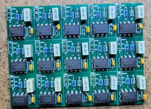
Yep, the old BOM didn't work, I had to scrounge around for substitutes. Since most of the requests were for A&T, I just ordered a bunch of boards and components and assembled them. I assemble them a panel at a time, more efficient than doing one at a time. I have lots of the blank boards now.

I don’t know how many do try the DIY version. I just did it, a few months ago I did all the read watch to find the 1% resistors at Digi-Key. When I went to order found the TLC555CP was out of stock. When I did my quick once over figured the TLC555IP would be fine but since this popped back up figured I’d check with those smarter than me. That 10nf cap was still kinda up there but didn’t feel like finding a different one with same specs and footprint. PCB was already made. I got the 3M for 19.8¢ And the 47K .4W for 27.5¢
I did that mainly because I didn’t know of anything I needed from mouser that I could get to justify the cost of shipping
Any of the low power 555 DIP chips should work, the actual timing is the same for any of them.
@zhubl posted:...
PCB was already made. I got the 3M for 19.8¢ And the 47K .4W for 27.5¢
so just to be clear, the PCB can fit a 0.4 Watt resistor?

I didn't examine the PCB design, but the "original" BOM appears to have a 1/8W resistor (0.125 Watt). It kind of looks like the holes are spaced 0.3" as per the 0.1" grid protoboard above. You can generally fit a 1/4W resistor (0.25 Watt) in a 0.3" spacing. So even better if 0.4 Watt fits in the PCB design provided.
I realize we're talking nickels-and-dimes but always good to know what options are available!
The resistor hole spacing on the the Rev. 3A version of the WD board is 6.5mm. I picked resistors that would fit, typically 1/8w. Some of the precision 1% resistors of higher power ratings are short enough to work also, just check the datasheet before you order them.
All good information as usual guys. The bigger power resistor did indeed just barely fit. Here’s how mine turned out. I don’t know why it never crossed my mind that I could simply get a smaller watt resistor but oh well live and learn I suppose.
The electrons will never know they have to take a detour through the big resistor. ![]()
@gunrunnerjohn posted:The resistor hole spacing on the the Rev. 3A version of the WD board is 6.5mm. I picked resistors that would fit, typically 1/8w. Some of the precision 1% resistors of higher power ratings are short enough to work also, just check the datasheet before you order them.
Would there be an issue with mounting a physically "oversized" resistor to the PCB vertically (where the bottom lead goes straight down through the hole and the top lead has a ~180 degree bend to line up with the other hole? Would this arrangement add unwanted capacitance?
It won't hurt anything Steve, but be mindful of the clearance needed between the PBW and the main board. I'd do what Zachariah did with the resistor. Or, you can just use the right sized resistor! ![]()
Access to this requires an OGR Forum Supporting Membership
