


Do you have an over all picture of the tender harness?
@Lou1985: See photo attached. The tender harness is a typical 10 pin, and I'm still really stumped on that secondary tender connector inside the tender. To be fair, this board was not original with the S1, it is stolen from a RK diesel. So maybe I'm supposed to have a separate 10pin-10pin Female-female tender harness that goes from the loco connector, through the tender to the vertical connector, then somehow that feeds the board? The tender cable / harness you see here WAS already pre-wired to that connector, so It gets used somehow.

I've played around quite a bit with the boards and wiring and I've got some more things figured out, but that odd 10 pin connector mounted vertically in the tender is still confusing me.
I have found the connector that attaches the PS2 board to the MUX board in the tender, and I can sort of trace what wire do what based on the pinouts of the PS2 board. There's a purple wire that runs through the tender harness to the loco and I'm thinking it has something to do with MUX board power or something, since it doesn't seem to be right for the "Normal" PS2 outputs.
On the engine side, I figure out that there are too may lights to be connected just to the RX MUX connector, and I realized I needed to install a secondary light distribution board (I had one sitting around). So I just need to figure out which wires I still need to add to the empty MUX pinouts and run them to the aux board, then I should have enough connectors for all my lights.
I also think that since this particular PS2 board was stolen from a RK diesel, there are several pinouts that I could / should connect from the PS2 to the tender MUX in order to make sure I can take advantage of all lights in the engine. (photo is my own aux board I had from another project, so colors and IDs don't really apply. I've got 4 wires I can use already (just need to plug them into the correct MUX pinouts) and one more location I can solder another wire to for 5 total jacks available.

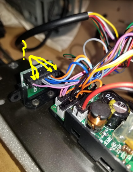
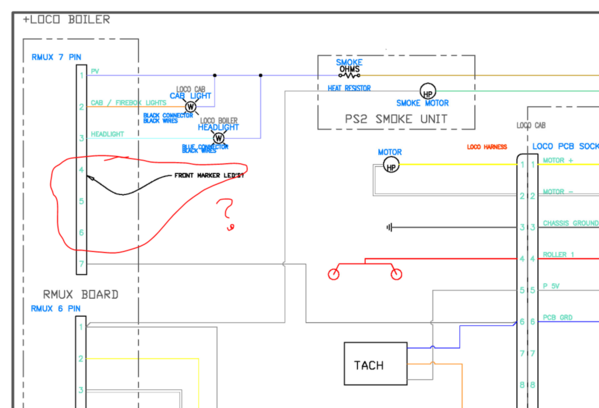
For the lights, I can see (pretty sure these are right)

- Yellow connector with B&W wires : Marker lights in front of number boards (Grain of Wheat red LEDs)
- Blue connector with 2 black wires: Headlight
- Black connector with 4 black wires: Number board lights (mounted to the same bracket as the headlight, this was easy)
- Red connector with Purple & Brown wires: Smoke motor
- White / Olive Green Connector with Green & Gray wires : Smoke Heat element
- Black connector with Orange and Purple wires: Connects to Firebox and cab lights
- (Not shown in photos) Olive green connecter with black wires is another clear white LED with about a 10cm harness that I can't figure out where it goes. It's the same LED as the headlight. Can't find any holes in the loco shell that make sense for it. Is there some sort of beacon light or flasher? Or does it somehow go in the tender as a backup light or something?
I figure any of the connectors that don't have a mate mounted directly to the MUX RX board, then I can use the auxiliary light board. I just need to figure out where to add the pinouts to the empty MUX slots and then plug the correct connectors to the aux board.
There's a couple additional Overall photos attached, as well as this photo of the engine tether connector:

If anyone on this board has any photos of the complete S1 guts fully installed, it would be a huge help. But I know that's asking a lot.
Once I figure out all of the electrical connections, I'm going to set it all aside and paint the shells.
Thanks for everyone's help so far!
Attachments
Images (8)


The electrical on PS2 steam should be straight forward. You can use the upgrade kit instructions on what the wires do and where they go. How they get there in this instance, is up to you!
make double sure, that no electrical wires or pins can touch metal!
The tender to locomotive tether doesn't plug into that 10 pin connector in the tender? Next time I have one of my factory PS2 3V locomotives on the bench I'll pull the tender shell off and snap a picture. One of the techs might have a wiring diagram they can send you.
PS2 3V boards are the same between diesel and steam. Same connectors and everything. So that board being out of a diesel has no effect.
The 10-pin extension cable does indeed plug into the mating plug in the tender. This is a fairly common arrangement in Premier steam.
Ok, after @Lou1985 and @gunrunnerjohn's replies, now I'm even more confused.
The tether that I have has a single 10 pin female connector that we're all used to seeing, and it appears to have all the same wires coming out on the tender side as the tether connector at the loco: 3 encoder wires blue gray orange; 2 power wires red black; 2 motor leads yellow and white; 2 smoke leads blue and brown; 1 mystery purple wire that comes from the MUX. The tether appears to match the loco pinouts exactly.
The wires come out of the tether and are configured with the standard Molex inline connectors and they plug right into the PS2 board. So I'm pretty convinced that the tether you see in my photos plugs to the loco and to the PS2 board, not to the odd port in the tender.
There would be no sense in plugging that tether connector into the 10 pin connector on the tender, it would just run in circles (and leave me without connection to the loco). But even if I got a different tether that had female 10 pin connector on both ends, I would then be missing the Molex connections at the PS2 board.
It really appears that the 10 pin connector mounted in the tender is some sort of way to connect an auxiliary tender?
A photo would really be helpful if anyone has a way to share one.
Thanks!
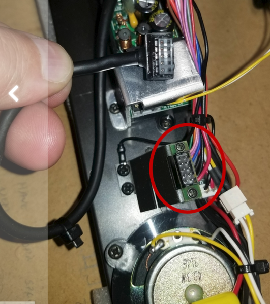
Sorry, I didn't look at the pictures all that closely, I was reacting to the text and misinterpreted what you were describing. The connector circled below goes to the switches and volume control on a small PCB in the tender shell. There's a harness that comes down and connects to this connector so you can separate the shell from the tender frame.
If you're missing that PCB and harness, you'll have to trace it out and wire something up for the switches and pot.
Attachments
Images (1)

Ok that makes more sense. I'm probably going to see if MTH had any of those boards in stock or I'll see if anyone here has one for sale before I try to cobble something together.
Does that PCB only act as a distribution board, or is there any voltage regulator or logic in it? If it's just a bunch of connectors and traces, then I should be able to rig something up way easier.
Still need to figure out how/where to add wires to the loco MUX board to control my additional lights.
By the way... What the heck does MUX stand for?
It's just a connection board, all the logic is down below. I've never seen so much as a resistor on any of them. Look under the hatch on the tender shell and see what switches (or holes for switches) are there. The only S1 I find with PS/2 on the MTH site is the 2003 model which apparently wouldn't have 3/2 rail capability, so I'd only expect to find a smoke switch and a volume control. Not sure why they have ten pins, so maybe this was a prototype that never made it to market.
John,
I took a look underneath, and all 10 pins are connected.
I'm going to trace them out maybe tomorrow, but here's a couple photos:


Attachments
Images (2)
What di the switch positions under the hatch on the tender look like?
@gunrunnerjohn: the tender shell appears to have locations for two switches and a volume pot.
I'm in the process of trying to map everything out, but thought I'd share the attached photo.

I'm thinking red is volume pot. Green is smoke switch (says so on top of the shell with cast-in lettering saying "smoke unit on/offc)
Orange=??
Orange has cast-in standoffs so the switch that fits there would be deeper / larger.
The tender appears to have two holes in the back for backup lights. Maybe something to do with that?
Attachments
Images (1)

ps2 3 volt charge port is my guess
Joe is correct, see the corner cut in that 3rd hole? That matches up with the shape of the charging port. So, the connections to those controls, and the tender markers and backup light account for the pins in that 10-pin connector.
There should be some sort of cover over the switches...
John, this was one of the engineering samples from the MTH auction. It came incomplete, but with most of the parts needed minus the board and motor / drivetrain (which I've since procured). So that's why there's no cover over the switch ports yet (although I do have them).
Yes the charge port makes sense to me, should have thought of that. I've got a BCR for it, so I will just leave that hole alone. I think I've figured out most of the pins on the internal tender connection that we've been talking about. I'll share a photo / diagram of what I think is going on later.
Jeff
Do you have the harness with the switches and charge port that mounts in the tender shell?
@Lou1985 posted:Do you have the harness with the switches and charge port that mounts in the tender shell?
No, I don't. But I do have a few random switches and vol pots laying around that I can use. I'm not going to need the charge port since I've got a BCR installed.
Although just having that harness would be helpful to understand what the other pins went to. I'm 79.2% sure it's for rear backup or marker lights based on what I'm seeing here. But not 100% just yet
Well, the backup lights and markers should be on that connector as it's typically the only thing that goes to the shell if it's there.
OK,
I think I've mapped everything out best as I can tell. There's a few lingering mysteries, mostly because I don't understand how a MUX works.
I've attached a jpg of my wiring schematic as I have it now. I named the pinouts as they are connected, unless I wasn't sure then I used pinout names that @gunrunnerjohn used in his diesel PS2 pinout diagram he posted a while ago. I also included a couple of notes.
Here's what I am thinking / questions I have now:
- The version of the S1 that I have (was an engineering sample) does NOT have a backup lamp. The only location for any sort of lights in the tender that I can find is a pair of red grain-of-wheat LEDs that go in as markers in the rear corners of the tender. With that being the case, I'm wondering if I need to connect those lights to either pin 6 or 7 on the mystery auxiliary tender connector:

- The 8-pin connector on the PS2 board has pins 1 and 3 jumpered, with pin 1 going to the AUX connector in the tender. But pin 5 (a gray wire) also goes to the AUX. I am assuming that one of these two should drive the rear markers instead of the green wire that would have gone to the backup light?
- Why are the orange pins 1 and 3 jumpered like that?
- I don't understand the purple wire going from the MUX in the tender to the tether connector. It doesn't seem like it's Positive 6 volts like the other purple wires.
- There's also the doubled up gray wires on pin 4 of the tender MUX that should be +5volts but I have no idea where that power comes from. It doesn't appear to connect to any source that can generate 5 volts, unless its done up in the front MUX board and that's what passes through the tender? Then I don't understand the smoke motor circuit and how it is used on the main PS2 board.
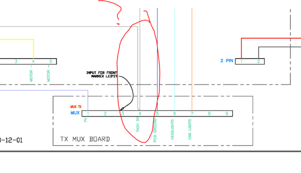
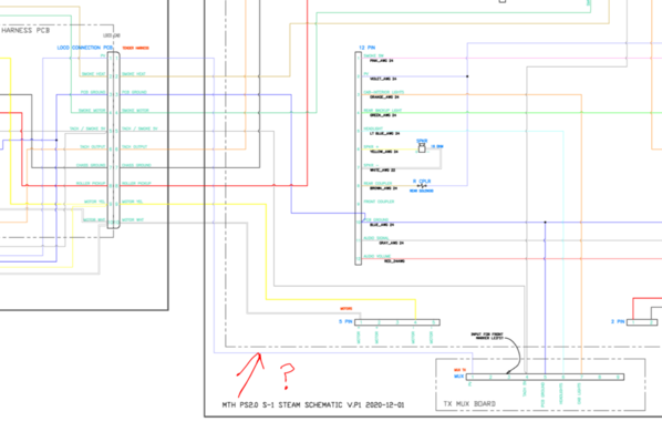
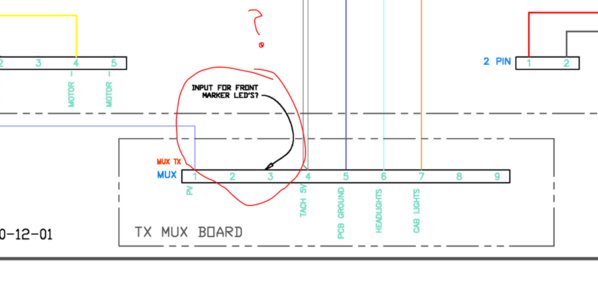
- After looking over the entire loco shell, I don't think I actually need the auxiliary power distribution board that I thought I did. The only output that I can't find a home for is the front marker lights. There's a pair of them that are wired to a connector in parallel, but no place to plug them in. Is it possible that these can be one of the empty pinouts on the MUX boiler board? And if so, what pin of the transmit MUX corresponds to the empty pins of the receive MUX? It's not like I can just test continuity...
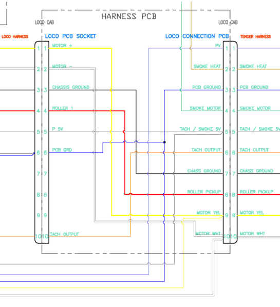
- There's a bunch of internal traces that connect the two 10-pin tether connectors on a PCB at the tender tether mount in the loco cab. Although I can't be 100% certain that these are the correct interconnects between pins, this seems like a logical arrangement based on the connections forward to the boiler MUX and smoke units. If anyone has a better diagram of this PCB with the traces, would like to see it:
I *think* I'm pretty close, but would be really nice if @Lou1985, @GGG, @gunrunnerjohn or anyone else who is smarter than me would check it over before I apply any power and risk blowing up my fancy board.
Also, this was my first crack at using AutoCAD's electrical schematic tools. It's not the Mona Lisa, but I think it's clear enough if you zoom in on the attached overall jpg to see the details. Open or save the overall image from the attachments bar. I tried to keep the colors of the wires correct per what I actually have on hand.
Edit: Seems like the image uploader compresses the JPG to the point that you can't read any text. I also attached a PDF if anyone wants to download and look at a clearer version.
Thanks again guys (and gals?).
Jeff
Attachments
Images (7)


Files (1)
You should attach those diagrams you have questions on in a ZIP file at full resolution. They're too small to see detail in the post.
John, there is a full-resolution PDF attached at the bottom. I don't have much luck converting to high res jpg.
Most PS2 3V Premier steam is wired pretty much the same. Techs usually have the wiring diagrams, but I can understand why they wouldn't want to share them.
UPDATE:
Got the drivetrain all installed and she's super snug. Everything aligns well (using the MTH provided worms and some purchases spacers and shims) and the motor and both worm gears turn smoothly at 5 volts.
I greased 'er up (including the dogbone couplings) and let 'er run both directions for a while.
There's noticeable lateral play in the forward drive axle and it tends to walk left and right when it's not loaded under the weight of the loco. The plethora of linkages seems to play into that. You can see in the attached video. Once there is any radial load applied to the bottom of the wheel it goes away.
Also, the front left linkage assembly was "ticking" each rotation. Found out that the furthest outside linkage, which was a straight bar, was not clearing the fastener that held the linkage to the crank mounted to the drive axle. I guess it was a prototype issue (not prototype as in real life...prototype as in engineering sample of this toy). I also notices that the other 3 comparable linkages were all slightly bowed outward and just barely cleared the screw head. So I just bowed the last one a tiny bit as well.
So now I really just need to finalize the electronics. I posted my best shot at a full schematic via a PDF in a previous post. There are a couple specific questions that I would like to get some feedback on before powering up the PS2 card, just don't want to ruin it.
Attachments
Videos (1)

Jeff, I’m not convinced you’re out of the woods mechanically just yet,....I could be wrong but looking at that video, that one wheel set looks mighty sketchy,....that’s the chances we’re all taking with these engineering samples, is all the sorting out that needs to be done before we wind up with a functioning model.....what I do on a circumstance like this, is either wire in a simple cheap bridge rectifier from the pick up rollers and run it real world on the layout, or just wire it up straight DC and temporarily wire a loop of track and test it with a straight DC transformer....and having a way to monitor amp draws is helpful.....testing in an environment like that is far less expensive than buying boards after boards.....I’d run it somehow on a loop of track somehow, someway shell on, and look for deficiencies that way,....try it with out the shell, and with,.....best to sort out known mechanical issues now, rather than an issue wiping out a board...also, no need to grease dog bone coupler cups,...that’s a nylon dog bone, that grease will just sling everywhere making a mess....
Pat
I agree that the lateral play is sketchy. When I tweaked the linkage it improved quite a bit, although it runs much less janky in reverse so maybe there is a slight problem with the forward worm somehow.
I was able to run it back and forth over a couple feet of straight track over an over (using an external 5V wall wart and some clips) and it seems to run smoothly over straight track. But I might do what you said and just throw a rectifier on there and give it some AC from track voltage to be able to try different speeds. However, I don't have access to 072 loops anywhere...even the layout we're doing at Dad's is 063 max. I bought it more as a project than a runner, although we do plan to run it back and forth over the approximately 22 feet of straight track we will have in our yard just for kicks.
I'll measure amps with my fluke, but I'll have to do it at my dad's place to be able to run the loco under its own load long enough for me to get a reading.
Also, noted on the dogbones, although I was reading a different thread where someone was complaining about the nylon dogbones getting eaten up and everyone was telling him they should have some grease on them. Anyway, the mess was already made and any grease left is thin enough to not bother me.
Thanks for the input!
Dad is considering listing it for sale if we get it all working, and maybe using the proceeds to fund another Premier steam project that can run on our layout! It's funny, because I posted in my other thread (layout build) that we would never own an engine large enough to require 072 curves...yet here we are only 6 months after I wrote that!
Jeff, I think I remember that thread where somebody said plop grease in the cups,...that’s a band-aid solution at best....and I’m pretty sure I mentioned that on there..... best to smoke a .59 cent rectifier than a 200-300 dollar set of boards I don’t like magic smoke,......the only thing magic smoke knows is the word X-pensive...😁
Pat
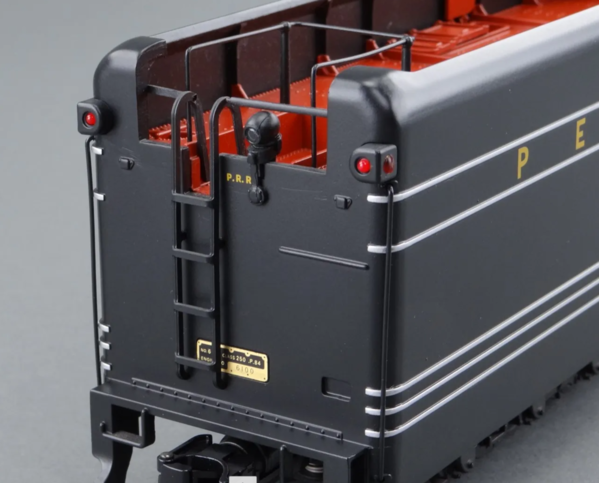
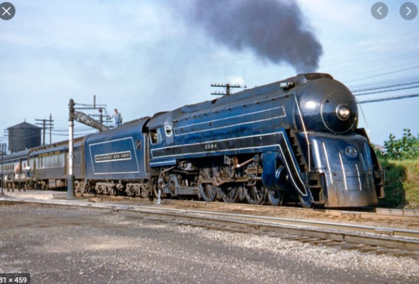
So, back on electronics...turns out there IS a rear backup light, it's just not integrated into the tender. So that solves one more little mystery. Problem is, I do not have in my parts bag the stanchion that the light installs into (you can see it installed right next to the PRR decal on the photo attached). Can anyone recommend a source for something similar (not going to hold out hope that I can find one specifically for this...maybe I'll check the Lionel version parts list):
Also, it appears that the rear lights have the LED installed facing backwards, and just a passive red lens on the outsides. Solves another mystery for me.
Getting closer.
Also...dad wants a B&O gray / Blue / gold scheme. Yes, I know B&O never ran an S-1. Dad doesn't care. And it's his money. I'm going to need a source for just basic white / gold pinstripe decals of various width.
Attachments
Images (2)


Update:
So I'm pretty sure I've got the electronics figured out. I only had one small mistake in the schematic I posted previously, which was that the interior connection n the engine tether board was not continuous between pin 5 on the tender side and pin 5 on the engine side. That was all I could find after spending a couple hours ringing out the connections to be sure I had things plugged in where they needed to be.
So, I carefully powered up (with TVS installed) using my KW, and...Success! Headlight, cab lights came on, engine functioned in conventional mode just fine!
I need to figure out which MUX output controls the front number boards and add a wire / connector for those. And I still need a rear backup light (posted in the WTB section). But I'm starting to feel like I've got this licked!
So, next question regarding paint:
The shell is not painted and as of right now does not have any of the detail pieces installed / applied. IF the shells are to be painted, now is the time to do it (prior to putting the whistles / engineer / firebox / lights) on the loco. But I believe we're likely going to sell the engine. If we sell it, would it be better to sell unpainted and with all detail pieces left off (so new owner can paint more conveniently) or should I put it all together unpainted so it leeks better in photos for selling?
Or I might end up keeping it and doing the blue livery, even though we can't run it...
What to do...
Update: I have a working loco!
I posted some final info in my Electronics thread, but I'll take some more photos and videos and post them here once I get the shell and decorations finished.
Here's the thread with the finished electrical system:
https://ogrforum.ogaugerr.com/...c/153463017389153551
I know it's somewhat common for lots of y'all to do these sorts of things. But I'm totally stoked that I learned how to bring a mechanically and electrically gutted locomotive to life! I now have a truly unique piece of MTH history.
Still need to find someone local who has a programming track so I can load the correct sound file. Or is there a way to load it without a TIU by plugging directly into something?
Thanks for all the help!
Attachments
Videos (1)

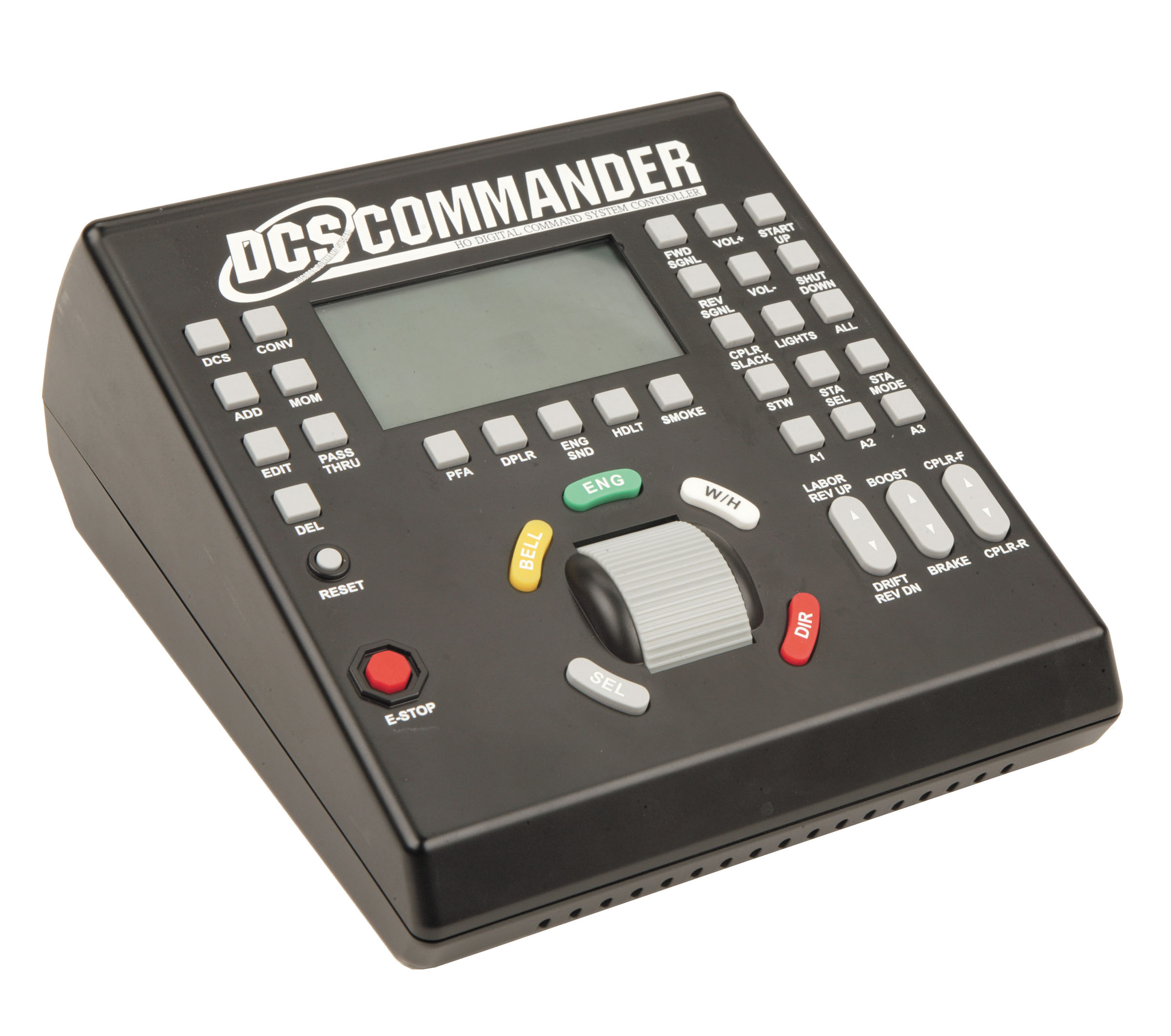
You need a TIU or at least the Remote Commander to load a sound file.
@gunrunnerjohn posted:You need a TIU or at least the Remote Commander to load a sound file.
You can use a DCS remote commander to load a sound file? That's news to me.
Congratulations! Nice addition to your fleet especially since you made it work!
@Lou1985 posted:You can use a DCS remote commander to load a sound file? That's news to me.
Me too.
Sorry, the DCS Commander, not the Remote Commander!
Ah ok that makes sense.
Add Reply
Sign In To Reply
