I’ve seen houses with copper plumbing where the plumbing is connected back to the electric entry panel ground. I think that was a safety in case a live wire was accidentally touched to the copper pipe system. That’s different than what was stated here, but I’m wondering if that’s recommended any longer. I’m thinking that could be an unrecommended additional ground rod in the soil as one caveat.
Anyway, if that is the case and it’s been allowed, ground wires to lay on the layout could just get their ground system signal from a nearby copper pipe.
What does the ground book say about that these days?
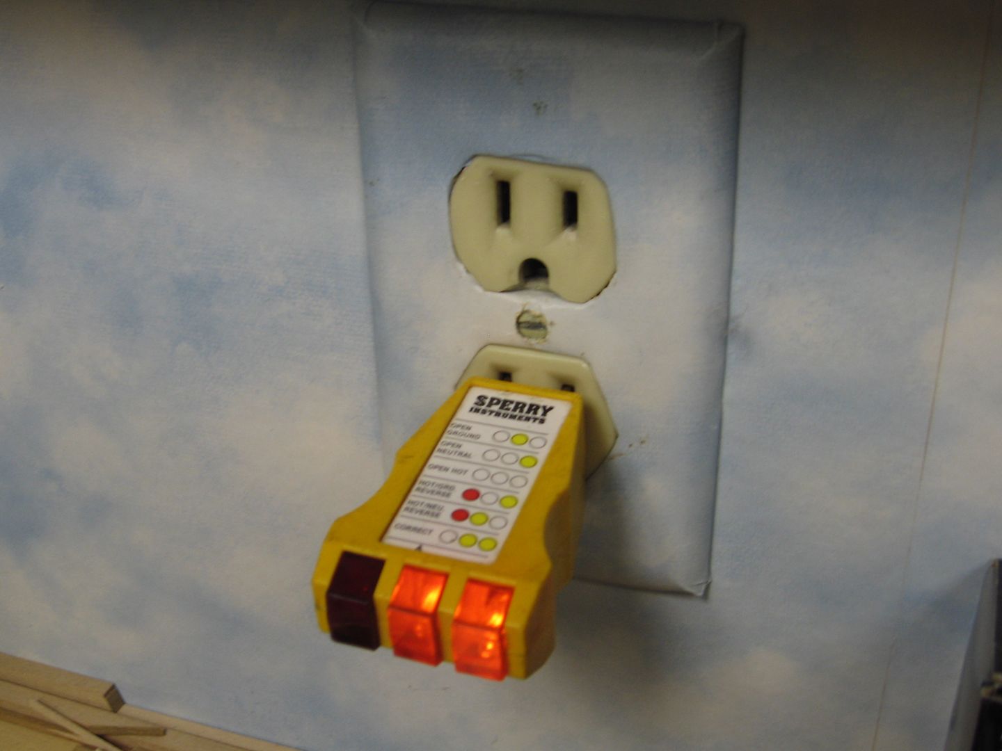
I guess our condo didn't get the word that that was prohibited! The one wire is going around the meter and valves, and in the corner shot, the ground wire from the water feed is going up is the power panel ground.
To paraphrase the National Electrical Code-
1. A metallic water system that has at least 10 feet of buried metallic pipe MAY be used as one of the required grounding electrodes.
2. If the metallic water system is used as a grounding electrode, the grounding electrode conductor MUST be attached within 5 feet of the pipe's entry into the premises.
3. If the premises contain a metallic water piping system, it MUST be grounded, even if it not used AS the grounding electrode.
4. In the situation where a 3 prong receptacle is used to replace a 2 prong receptacle, the ground pin MAY NOT be connected to the metallic piping system UNLESS the connection is made within 5 feet of the system's entry to the building, per 2 above.
There are a bunch of exceptions and clarifications, but the above 4 points are the jist of it. Not all jurisdictions follow the NEC, so your inspector may be more or less stringent..
All this has changed a bunch over the years, mainly due to situations where sections of rusted or damaged water pipe were replaced with plastic, which broke the ground path.
FWIW, the stuff about ground currents causing corrosion is true, I have personally encountered it, although it took 50 years to show up.