
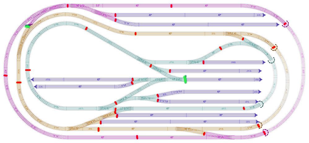
I have finally reached the home stretch of my layout design.  I've got the track plan, but now I need help with the wiring plan.  Here is the layout:

Layout v131 track

I'll use Atlas track, and a have a ZW-C with 4 180W power bricks to power it, as well as a couple CW-80s.  I have TMCC/Legacy as the control, and will be running conventional at times.  What I want is help on how to proceed, to learn from those that do know, what are the best practices. 

Here is where I was thinking of making my blocks.  I'd put the plastic rail joiners on the center rail at each red mark, and on one of the outer rails at the red marks on the 3 loops so that I can use Atlas's signals.

 Layout v131 track marked

My 1st thoughts early on was to make a control panel that had a 4 way switch for every block so that I could set any track to be controlled by any handle on my ZW.  This way I could run a conventional locomotive between loops without keeping track of more than one handle, but that's going to make a rat's nest of a wiring nightmare.  But recently I've began to realize that I as I get more Legacy locomotives, I really like using the remote to drive, and have plans to upgrade most of my locomotives to TMCC, but then I also still have a couple locomotives that I don't want to upgrade, so running them between loops will be a pain.  What does everyone else do about this?  I was thinking a handle for each loop, and the 4th for the spurs, using a CW-80 for the lit buildings and another CW-80 for accessories, or I could power spurs with the same handle as the loop they are on, and use the 4th handle for lights and accessories.  But then I still have the problem with moving a conventional locomotive from loop to loop.

Attachments

Images (2)
  • Layout v131 track
  • Layout v131 track marked
Last edited by sinclair
Original Post

Replies sorted oldest to newest

hey,

I would simplify it for your conventional engines and separate the inner and outer loops at the crossovers into two power districts. Then keep the conventional engines on the same loop and not crossover.

That would allow a conventional to run on one loop while running a command engine on the other. Assign the A & D handles to each respectively.

That would also permit you to operate the track voltage with the remote if desired.

Your diagram edited with a green mark attached.


The blocks look a bit short for train detection as a complete train will occupy multiple blocks at one time, but I guess that still works. Also, I think they are double what you need as power drops, but could provide the detailed block control if desired.

I would run a bus down the center with 12 position terminal blocks, using a common for all, and a color for each channel of the ZW-C. Jumpers will permit use of multiple terminals for the track power feeds. This will eliminate the rat's nest. Check some of aubv's posts. He and MontanaRailPower have the terminal block and jumpers.

Attachments

Images (1)
  • Sinclair_Layout_v131_track_marked

I did miss a red dot, where you put a green one.  It was late when I posted.

And yes, I know the blocks are small but I run mostly 1 locomotive + 5 cars + caboose.  I can run 2 trains at once on the outer loop with Legacy (Sometimes I get real adventurous and run 3 trains.) so small blocks allow for there to be a green signal between trains, at least that's the theory anyway.

After sleeping on it and reading you post, I think what I'll do it pump 3 of the handles into a switch that selects the loop the handle will power, and use the 4th handle for lights and accessories.  This will allow for conventional trains to cross loops, and keep the wiring simple.

And you think I only need one power drop between red lines to keep a solid 18 volts at the track?

sinclair posted:

I did miss a red dot, where you put a green one.  It was late when I posted.

And yes, I know the blocks are small but I run mostly 1 locomotive + 5 cars + caboose.  I can run 2 trains at once on the outer loop with Legacy (Sometimes I get real adventurous and run 3 trains.) so small blocks allow for there to be a green signal between trains, at least that's the theory anyway.

After sleeping on it and reading you post, I think what I'll do it pump 3 of the handles into a switch that selects the loop the handle will power, and use the 4th handle for lights and accessories.  This will allow for conventional trains to cross loops, and keep the wiring simple.

And you think I only need one power drop between red lines to keep a solid 18 volts at the track?

I couldn't quickly find Dale H. 's comments regarding conventional running and crossing power districts. The trick is to keep the voltage the same to avoid bridging the transformers or channels. That adds the two voltages. Post-war motors can handle some variation. Lighted-cars - Dale puts diodes in opposite directions in alternating cars - Modern electronic conventional engines - not sure.

I consider a power drop as a hot & common pair. So, yes, between your red dot markings will be more than enough.


Gregg posted:

Huh! although the thread title is similar I'm not sure why you would close the thread. We didn't get to find out what the poster had in mind layout wise. The replies were heading in that direction and an explanation to follow.

  Anyway here's the locked thread link...

https://ogrforum.ogaugerr.com/topic/power-drops

I guess you didn't notice that I was the poster of both the locked thread and this thread?  I had started both threads with different questions, but since they were both headed the same direction, and this one answered the questions posters were asking me about my layout, I linked to this thread.  An OGR mod noticed and decided to close the other one to keep the info in one place, which is fine by me as I was planning to make that request anyway.

Moonman posted:
sinclair posted:

I did miss a red dot, where you put a green one.  It was late when I posted.

And yes, I know the blocks are small but I run mostly 1 locomotive + 5 cars + caboose.  I can run 2 trains at once on the outer loop with Legacy (Sometimes I get real adventurous and run 3 trains.) so small blocks allow for there to be a green signal between trains, at least that's the theory anyway.

After sleeping on it and reading you post, I think what I'll do it pump 3 of the handles into a switch that selects the loop the handle will power, and use the 4th handle for lights and accessories.  This will allow for conventional trains to cross loops, and keep the wiring simple.

And you think I only need one power drop between red lines to keep a solid 18 volts at the track?

I couldn't quickly find Dale H. 's comments regarding conventional running and crossing power districts. The trick is to keep the voltage the same to avoid bridging the transformers or channels. That adds the two voltages. Post-war motors can handle some variation. Lighted-cars - Dale puts diodes in opposite directions in alternating cars - Modern electronic conventional engines - not sure.

I consider a power drop as a hot & common pair. So, yes, between your red dot markings will be more than enough.

I think I've got Dale's comments bookmarked somewhere as I had come across them.  I've got the meter accessory on top of my ZW-C, so I can see what voltage it's putting out.  I'm going to sit down and go over the power blocking and signal blocks again in the next couple days with the info I've gotten from these threads in mind.  I know someone from the other thread said wiring would be different with DCS in mind, anyone know what that would be and could give a summary?  At this point I don't have an interest in DCS, but it would be a pain if I got into it years later and had to do some major rework to get it to work.

Sinclair, With DCS the thing to do is make sure (As best is possible) that an engine can only receive electricity in one path.  basically this mean that each isolated block of track is powered by exactly one pair of feed wires.  No trouble to do from the start with the track plan you have and the blocks suggested.  I believe that 12 track joints is the limit for a block for DCS to preserve the signal.  

On to other things;  I think it would help to define better exactly what your goal is. It seems that you want block signals that show where trains are to allow 2 or 3 trains to be running on each loop, but there is no need to independently control power to each  block, ad you'll be running legacy engines here when more than one engine is on the same loop.  but you still want to be able to run conventional engines between loops and such as well.  

I do not know if it would suit your needs or not, but given your layout here is what I would do.  rather than each block having it's own power switch, O would give each Loop it's own switch.  the blocks then will be used only for signaling, and keeping up a good DCS signal if you go that way.  Here is what I have in mind:

Each color coded 'loop' would have all it's feeds tied to a switch to allow you to select which transformer or handle to power it.  then each siding would have its own power switch as well.  In the name of cost savings I would use double throw, center off switches for the sidings, letting you choose between only  2 handles (and off) for them, as 4 position switches for high current can get expensive.  Another option could be to use standard, low current rotary switches for selection and relays to actually power the track.  

JGL

Edit:  as an afterthought, you could also do away with selecting handles all together and simply have each of the three loops connected to a handle, then use simple on-off switches to turn on the sidings connected to whichever loop they connect to.  It's not fancy, but it works and is simple and cheap.  

Also, worth noting that this all assumes running command locomotives, or a single conventional on a particular loop.  things get very complex, rather quickly for running multiple conventional engines on one loop. 

Last edited by JohnGaltLine

Sinclair:

I am a little late to the thread but a couple of thoughts.

1 - I like to leave track for powering trains only. I always ground both outside rails not trusting train trucks to complete the circuit.  Isolating outside track for accessories while a valid technique for some reason worries me. With that said have you considered  IR detectors for your accessories, signals and lights? You could use you CW-80s to power everything and leave the AC transformers for trains.

2 - Since you are using TMCC/Legacy have you thought about using power masters or TPC's? The advantages include an excellent fuse capability and the ability to run conventional or command control through your remote. You can also purchase power bricks as opposed to more expensive transformers.

1.  IR sensors will not allow for true train block signaling.  I plan on using the Atlas signals, and many have others have done so without issues, and this is how Atlas does it.  I've also run on Atlas 3R track before without tying the outside rails and never had issues.

2.  I already have the ZW-C, so buying PowerMasters or TPC's would be more money.  The ZW-C can control track power just like the PowerMasters anyway, and the PH-180 brick's trip breaker has been more than fast enough to catch shorts (Almost too good, I wish it was slower actually.).

Add Reply

Post

OGR Publishing, Inc., 1310 Eastside Centre Ct, Suite 6, Mountain Home, AR 72653
800-980-OGRR (6477)
www.ogaugerr.com

×
×
×
×
Link copied to your clipboard.
×
×