I've posted elsewhere about two ATSF locos that were planned but cancelled, which I have decided I want to run on my layout and so must build.  A number of folks have asked for photos, etc., as I go along rather than just when done, including my showing the learning experiences (i.e., what doesn't work).  I decided rather than update those three other threads I would unify everything here.  I will add to this thread from time to time as I make progress of run into more "learning experience."  


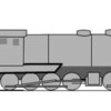
The first of these two locos was a 6-4-4-4 steamlined cab-forward, 100 mph-cruise postwar oil-fired steamer to pull the Super Chief - think of PRR T-1 turned around with a diesel type cab forward and you pretty much have it, at least as pictured in E.D. Worley's Iron Horses of the Santa Fe Trail.  Photo below is of it as of this afternoon: Made from a scale TMCC T-1 and a MTH Premier dummy F3 cab, front truck from my spare/junked loco parts box.  Most of the heavy work is done: the model looks almost exactly like the drawing in the book except for sun shades over the cab front windows, which I will add later.  The only mod required beyond cosmetic bashing was to move the wireless coupler to the ofter end of the loco.  It runs well with the front truck behaving itself and tracking well.  A lot of detail work and rather involved paint to do yet (Warbonnet, of course!).  I may replace the T-1's tender with an all-new body rather than try to modify this one: the two drawings on have of this show it with what looked much more like the tender from a UP Veranda turbine than an oil-version of this one. 

DSCN5210


The second loco is a much more challenging build.  It is a Pentuplex -  a 2-8-8-8-8-8-2 proposed just before WWI by Baldwin for Santa Fe in 1913.  Had the war, USRA standards, etc., not intervened it might have been built: the longest, heaviest, steam loco ever with more pull that two Mallets.  It was to have cab forward and a cab in the rear, too, and was to have a flexible joint in the boiler as well as a flex-jointed, bendable tender.   This is my drawing of what it would have looked like, based on various books and internet references to it.  

big loco

I posted a picture some days back of the running chassis.  I never had any doubt I could make it work well (chassis from five Lionel RTR 0-8-0 locos).  It is the smoothest running loco I have ever seen, too: forty-four wheels and twelve center pickups don't lose connectivity with the track for even a millisecond for its five flywheel motors.  Photo and video below show it with experimental body #1, crude cardboard but it serves for the experiment.  aI discuss what works and what I have learned for try #2 after the video.

DSCN5213

I always figured the real challenge would be building the loco body, from scratch, so the two flex joints work, and this is proving to be the case.  The cardboard body is crude and ugly cardboard and paper , and the boiler is too narrow and way too low - deliberately so, so as to really test clearances and space needs inside it.  This experiment is semi-successful.  The tender's flex-joint works well enough: I know how to engineer that now.  At the joint one tender has a rounded end (when viewed from above) that fits about an inch into the front of the other and rotates within it. it works well enough.  


The boiler joint is not satisfactory. I expected this but I had to try the obvious first: here, the two sections of the boiler are firmly attached to driver sets, the front to the leading driver set and the rear to the third driver set.  They meet over the middle of the second driver set, and my hope was that their ends would place nice with one another  so that I could just install a ball joint there to connect the two (it doesn't look like a ball exactly but that terms gets the idea across).  It does not work: the two boiler ends bounce and twist around, not alot, maybe only 1/4 inch at times, but enough relative to one another that with my ball joint connecting them, shake and twist their respective driver sets too much.  Next, I will try to "float" just one of the two halves of the boiler: I will leave the rear boiler secton firmly attached to its driver set, as now, but the front boiler halve will not be firmly attached to the leading driver set, instead, it will pivot at its front and its weight supported at that point and by the ball joint.  I should get that done by next week.  


Attachments

Images (3)
  • big loco
  • DSCN5210
  • DSCN5213
Videos (1)
Pentuplex alpha prototype
Original Post

Replies sorted oldest to newest

Amazing work yet again Lee. 


I have been pondering your boiler articulation problems, and unfortunately I think that I may have come up with another potential problem with a fixed length ball-joint type of connection. Have you considered the various motions that might be encountered in traversing an S-curve such as on a cross-over, or even a simple siding? Sorry for mentioning this if you have already considered it, but it seemed to be of enough significance to warrant mentioning.

Very neat and really interesting engineering problem.


Looking at the sketch and watching the video, I'm guessing the running gear "articulates" (not sure if that is the best choice for terminology) between each 0-8-0 module (with the 2 wheel leading and trailing trucks moving separately)?


It looks like the tender works pretty much like two very closely coupled cars with the rotation point between the 2 0-8-0 modules.


With the engine portion, you have 2 points of articulation for the 3 0-8-0 modules, so that for an S curve as NQDY mentions, the 3 0-8-0 modules could be at different angles to each other. But, as drawn in the sketch, the boiler only has 1 point of articulation at the middle of the middle 0-8-0 module. Seems like something has to give.


I'm thinking you are on the right track with the middle point of articulation and floating the boilers. I think you are right about a ball joint as I was originally thinking just a vertical joint, but there is an also an up and down articulation.


But, I think you are going to need to attach the boilers so they have a ball joint at each end of the boiler.


The one in the middle is a fixed point attached to the middle 0-8-0 module and it attaches to the 2 boiler halves so they can twist up and down and side to side.


The other end of each boiler (at the front and rear cab ends) also has a ball joint that allows the boiler to twist up and down and side to side.


BUT, I think these two end joints are also going to need to be able to have a limited amount of "float". Perhaps some sort of slot that allows the joint box (or whatever holds the joint) to move forward and rearward slightly. This would be to account for the change in distance as the 0-8-0 modules turn in relation to each other. Each boiler half is a fixed length, but say for example when the locomotive enters a turn, there is now an angle between the first and the second 0-8-0 modules. The front boiler half forms the third leg of the triangle between the two 0-8-0 modules, but it can't remain the same length as when there was no angle between the two 0-8-0 modules, i.e. a straight line. Having a floating joint at one end (near the cab) allows for the constantly changing distance of the third leg of the triangle. Note, you could have the front half of the boiler overhanging on one side of the locomotive while the back half overhanging on the other side when going through S curves.


I don't know if I did a very good job of explaining it, and it's easy for me to propose an idea and then you have to try and figure out how to build it. But, given your skill and resourcefulness, you'll probably have it done in about half an hour.

Last edited by trestrainfan

Lee,

I am attempting this build as well and like the photos of the live steam version that is what I will be going off of.  With three 0-8-0 drives close together it looks like you only need two boilers to make it work.  Fixed in the front and float the rear end looks like the way to go. I will know more when I get all of my parts in.


James

Last edited by ddgoose69

Progress in the last week was, inevitably, less than hoped for: good weather  meant a focus on yardwork and some projects outdoors, and I distracted myself with "Sharks" (separate post) which was a lot of fun.  Still, a bit of progress.


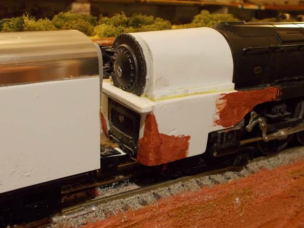
ATSF 6-4-4-4 cab-forward streamliner is looking good.  I somehow managed about six hours on this this week, it being my chief focus now.  I did some light tweaking of the relocated IR coupler: the coupling now fits in either of two positions, that shown, and one that reduces the gap to the tender to about 40% of that shown: just barely enough for 72" curves.  The modified  boiler shell at the rar and all is permanently installed along with all rear body modifications: you see styrene (white) and Bondo filler (red) which I will let harden for a few days before beginning finish work.

Slide1

Slide4


It won't be easy to see inside through the windows of the cab so I did not put a lot of detail in the cab, but I painted the instruments and made a scratch-built dashboard and console that fits nicely in the cab, so there will be some sense of details when one looks inside.  The figures are from the ten I harvested when I took apart the RTR 0-8-0 locos that make up the chassis for fantasy loco #2 (not much progress, but updated farther below).  

Slide2

After thinking about the tender, looking at the various artis'ts renderings of what this would have looked like, and playing with SuperChief cars (which it would have pulled) behind it, I removed and put aside the PRR tender shell and began to "scratch build" a steamlined fuel-oil-and-water tender that looks more like those in the drawings.  The shiny top is from an aluminum Super Chief passenger car - an old silhouette car I decided to sacrifice: it has exactly the roof profile need.  Sides are from .10 styrene sheet, as will be the ends (yet to make).  I will lower the height about 3/16 inch from what is shown in the photo below: I have to relocate one item inside before I can do that.  Once the body is complete I will add some a few details: a few filler hatches and hoses, etc., but the whole idea is for a pretty smooth  look leading into the shape of the passenger cars themselves. 

Slide3


The other fantasy loco, the 1913 Baldwin 2-8-8-8-8-8-2 pentuplex, saw no work at all this week worthy of pictures: I am concentrating on the 6-4-4-4 because I want the loco badly and it is not terribly difficult.  B y contrast, this is going to be a long slog that benefits from a lot of thinking and experimentation -  issues I have to solve.  This is a real challenge, and could take several months to get just right.  

  • I played with - several experiments - the "hinges" for the flexible boiler. Not entirely successful but getting there.   I need to find something that "fits" (doesn't look out of place or take up room I don't have) and that hinges in one direction (side to side) with ease, but provides real rigidity in the up down movement, not permitting any vertical rocking and angle change, etc..  I'm still playing with/thinking about this.
  • I've determining I have to make the chassis - all five 8-driver portions, heavier by around 4 to 6 ounces each, with as low a center of gravity as I can get.  Thinking about this too.

Attachments

Images (4)
  • Slide1
  • Slide2
  • Slide3
  • Slide4

Absolutely no progress to show on the 2-8-8-8-8-8-2, although I do have a new boiler hinge design in mind. FV-Trains was up from Florida and visited last Thursday and brought along his new Electroliner to run.  I studied the between-cars bellows on that model and it gave me ideas.


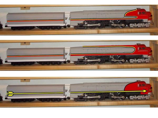
I've been focusing most of my energy on the streamlined cab-forward 6-4-4-4.  The pictures below are based on a photo taken yesterday, when it was still in primer.  It now has a new coat of Warbonnet type silver over everything but the cab, which I will let harden for a few days and them do red, yellow, black in that order.  I have three different possible paint schemes in mind as shown below, all variants on Warbonnet, of course.  Just curious which people like best - I don't promise to follow anyone's suggestions, but I will appreciate any input.  


Paint schemes

Attachments

Images (1)
  • Paint schemes
Last edited by Lee Willis

Add Reply

Post

OGR Publishing, Inc., 1310 Eastside Centre Ct, Suite 6, Mountain Home, AR 72653
800-980-OGRR (6477)
www.ogaugerr.com

×
×
×
×
Link copied to your clipboard.
×
×