


So would I

choochoopaul posted:...I realize that the functions of control with a handheld are lost with the addition of the board into the DCS-RC, but with a longer timed reset cycle could you send a data string to a engine between resets?
...
Yes you could. Obviously the factory-stock DCS-RC without the PBW (perpetual barking watchdog) board has a much longer reset cycle time of forever (it never resets unless you remove power)...and during that longer cycle is when data strings are sent to the engine under handheld control.
When you get your boards back, if you want to experiment with a longer reset cycle, probably the easiest is to put a capacitor in parallel with the existing capacitor. That is, it's arguably easier to tack a capacitor in parallel with an existing one (to increase it's value and hence the time delay) than to add a resistor in series with an existing one. It's the product of the R and C that sets the time delay so a 10% increase in the capacitance would increase the delay by 10%.
But, to repeat, I think you need to confirm your unmodified DCS-RC can start your PS engine silently in command mode in the first place. Again, I realize the TIU sends its watchdog for up to 45 seconds (depending on TIU Rev) but the fact is the DCS-RC sends that single 1/10th second burst just after it receives power. And that seems to be all that's needed to force a PS2/3 engine in silent command mode on power-up.
Another thought. I realize you'd need to factory-reset your engine to the default DCS address but did you confirm that your particular unmodified DCS-RC can in fact control an engine using the handheld remote?
Yes to all of the a fore mentioned questions. This morning with first one, then two, then three MTH engines all reset to address (0) sitting the longest distance from the power source on the layout. With the DCS-RC connected passively to the track and applying power, all three remained dark and silent. When the startup command was sent out all three woke up, and when commanded to blow their whistles they did, when commanded to move they all moved in a very bad looking consist. When commanded to shut down, they all did. I would say at this point I do have a working test bed with both the DCS-RC and the full DCS-TIU systems.
I even checked that with the very bad consist running around the loop of track, I could also fire up a Legacy TMCC engine on a siding connected to the same loop.
How much time does it take from the application of power to the DCS-RC to the start of the watchdog burst?
I am ready for the boards to return from their vacation out east.
choochoopaul posted:...How much time does it take from the application of power to the DCS-RC to the start of the watchdog burst?
I am ready for the boards to return from their vacation out east.
It would depend on the track supply voltage and if AC or DC since it is charging up some capacitors which then becomes regulated voltage to run the microprocessor. I have not measured this but I suspect it's less than 1 sec. Once the microprocessor starts running you would have the same 3/4 sec delay.
But didn't you report yesterday you powered up an unmodified DCS-RC on a short test track and the engine started up in conventional?
Stan2004:
What I did on Mondays testing was to power the network of a passively connected DCS-RC and at one second remove power to the DCS-RC but leave the power connected to the track. The test engine start up in conventional mode.
Looks like Friday that the boards return from their vacation trip. ![]()

Attachments
Images (1)

Thanks
I'm working on getting the clubs Noma station working again. Digital power converter, MP3 player with a chip to change the recording. You know the stuff from china, total about $9.00.
Has anyone besides Paul tried the watchdog boards? He had issues getting them to keep the engine silent and sent them back for me to test. I couldn't find any issue, and they worked here, but we may have overlooked something for other environments in our little science experiment. If you're tried them and they worked, or not worked, let's hear your story. I'm curious why we get different results from seemingly similar test setups.
I will be trying one of mine in a week or so, will let you know details of what happens. I guess I could try them all and report that too, while I am at it.
Yep, I hope we didn't make a lemon! I tried them here and they worked, I'm just wondering if there's an environmental issue in other locations that we didn't consider.
Hi,
I ordered and received three boards from OSH, but did not buy the parts yet.
As I saw some parts "tuning" discussion in this thread, could you re-confirm the exact and final parts list that you recommend to use.
I`ll report results when tested.
Thanks,
Daniel
The "tuning" is done with a scope, I set the retrigger time between 950ms and 1050ms by adjusting the value of R1 in the schematic. Values ranged from 1meg to 1.5meg.
GRJ,
Finally got to trying out one of the WD timers PBW's you made and it works fine here. I tried it on one spur track and it worked. While under the layout (scratching my head, looking at all the wires I have added and not documented ![]() ) I thought why not just connect it to the MTH terminal block I have feeding loop 2 with all the spurs and sidings on it. I have only been fiddling with one train and a PS3 RK RS3 engine, but that seems to work fine too. It's one of the newer ones that also starts with the thumb wheel, tried starting it both ways. I will get the rest of the trains back on the tracks and see if all is still well, but I see no reason they should not be just fine.
) I thought why not just connect it to the MTH terminal block I have feeding loop 2 with all the spurs and sidings on it. I have only been fiddling with one train and a PS3 RK RS3 engine, but that seems to work fine too. It's one of the newer ones that also starts with the thumb wheel, tried starting it both ways. I will get the rest of the trains back on the tracks and see if all is still well, but I see no reason they should not be just fine.
Forgot to add this earlier: The DCS-RC's green LED came on green when powered up and had a blip in it at just about 1 sec as near as I could time it with my watch. Pretty close anyway.
FWIW, if it helps with problem solving, here is my setup right now. Loop 2 (the one tested) is a center rail isolated loop using Atlas O-54 track. It has 2 inner sidings and 4 inner spurs. There are 4 blocks on the main and each siding/spur is isolated coming off the switch that feed it. The sidings and spurs are switched with LED rocker switches at a small panel. Each switch powers a relay that actually switches the track power, center rail only (small glitch with the switch's LED commons). All the power comes from an MTH terminal block and that is where I now have the DCS-RC PBW connected in passive mode. It feeds the entire loop, all sidings and spurs. Power source is PH-180 to PSX-AC to TIU to MTH terminal block, Legacy connected to TIU commons.
I will try the rest of the timers PBW's tomorrow with the same setup above. Will let you know on that too.
These are really pretty cool little devices, work great so far and no more watchdog problems. Just flip the power switch and go when ever you are ready! Also finally got my gantry crane track, found it on the front porch a couple days ago.
(Oops, was re-reading the problems above and noticed the proper name - Perpetual Barking Watchdog (PBW), post edited). ![]()
Great, glad to hear it works for you.
Is there still a problem? Heard from anyone else? Just wondering?
Paul had issues, and I don't know if he's made any progress. He sent all his modules and a DCS-RC base back to me and I tested all of them and they worked for me. That's why I'm curious as to other people's experience, there has to be an environmental issue that we're missing I would imagine. I actually got a couple more boards and built up a module so I could have one to test if more questions came up, I had previously sent them all out.
John,
Please pardon the delay, I work on the layout catch as catch can.
I was down there tonight attempting to electrically isolate the yard to allow me to completely turn off the individual tracks. I wanted to do that to see if I could first create the need for the watchdog signal thinking that way I could accurately test it with and without the chip.
Most of the time I was finding the things I put away for the project, i.e. rotary switch and electrical box so that it will be easier to deal with. I hope to work on it next weekend.
Ok, just re-read about half the thread and wondered of anything had changed?
I'll test the others I have and let you know about those tomorrow. I don't expect any problems.
All others are working just fine, like the first one. I fiddled with each one with 3 different engines (all PS3), different sidings, etc. and all worked as intended. Thanks again for all your work on these and thanks to Stan too.
Great, at least some environments are friendly to this solution. ![]()
Still re-reading the entire thread here. Probably should have mentioned that in the last testing I had the main connected to the PBW as well. Main had a Legacy engine and another PS3 on it, no problems there either, all seemed to work well.
Would probably be fine as is, but final install will be a re-wire so only the spur and siding tracks are on the PBW full time, main will be separate.
No reason the PBW won't work for a smaller set of tracks I would imagine. It works with a 40" section of Atlas track on my workbench! ![]()
GRJ, what did you end up doing at the club with the yard tracks and selector switch and everything that got this started?
Finally finished the re-read and had forgotten how this all got going.
Well, we still have the yard all pulled apart, we're embedding decoupling magnets into the tracks for each yard track. We're close to closing it all up and then I'll install my rig. Initial skywire tests worked out well, so I suspect it'll work.
gunrunnerjohn posted:The "tuning" is done with a scope, I set the retrigger time between 950ms and 1050ms by adjusting the value of R1 in the schematic. Values ranged from 1meg to 1.5meg.
I finally got it done and tested. It works perfectly.
The R1 tuned at 1.2meg gave me a cycle just a little over 1 sec.
The WD is clearly visible every second on the scope and, so far, while using the PBW in passive mode, I did not have any issue controlling the trains with the TIU.
Thanks for sharing the design, the Gerber files and the assembly details.

Attachments
Images (1)

Wow, the deluxe version with a socket for the chip! ![]()
gunrunnerjohn posted:Wow, the deluxe version with a socket for the chip!
It is in fact "Super Deluxe" :-) And it works !
OK when will I be able to get these.........Thank you........Clem k
I delivered a bunch of these some time back, I think you missed the boat. However, I do have a couple of blank boards and I believe still all the components to make a couple. Send me an email to my profile address if you want one and I'll whack it together for you.
GRJ,
My homework was to install the WDS signal and give a report. I set up my yard and isolated the tracks.
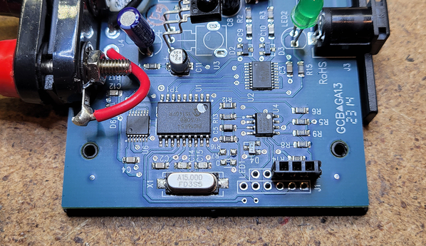
I read everything I could on the forum again and realized that while everyone was saying DCSRC (DCS remote commander) I was thinking DSC remote control. I actually took apart my remote control and realized that it was not the same board as the images or the discussion. Thanks to Barry's book no harm no foul.
I then took apart the precursor to the remote commander that I had from a RTR set from 2000. It does not appear to be the same board everyone else is using.
It has  more components and inputs for proto dispatch and proto cast.
Is there a spot on this board for me to connect your board?
I have included a picture of the board. I am stuck at this point and need to either find a remote commander board or rig up your circuit a different way.
My best excuse is that your watchdog signal ate my homework. Sorry for the pun.
Thanks for any suggestions.
Attachments
Images (1)

That looks like the older IR control for conventional locomotives,

That doesn't generate a DCS signal and obviously is of no use with the WD Generator board.
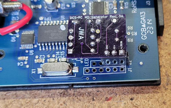
Just got one DCS-RC modified with the PBW and replaced on the layout. Works perfectly!
I found the underside pins did not need any trimming, and there is ample clearance inside the RC cover for the PBW board. Pretty slick.
I tried it on a couple of PS_2 engines, one on a t'table track and another in the adjacent yard. Both sit dark and quiet until started up, and I don't power these tracks until needed; well after the main TIU WD signal has come and gone. The green led on the RC blinks at a frequency of just longer than once per second. All good.
Thanks Stan and grj for a nice little add-on.
Cheers,
Rod
Thanks for the feedback Rod! It's really kind of amazing how this Internet thing works - not sure how the PBW would have come to be if not for the OGR Forum.
P.S. For those joining the discussion late, do not confuse PBW (Perpetual Barking Watchdog) with PBR (Pabst Blue Ribbon). ![]()
Success stories are always good. ![]() I think a few of my projects would have never happened if it weren't for the Internet. I love the instant feedback and alternate ideas that come up discussing these things, and usually a better design is the end result.
I think a few of my projects would have never happened if it weren't for the Internet. I love the instant feedback and alternate ideas that come up discussing these things, and usually a better design is the end result.
This one was kind of an exception, the design was really all Stan, there was no reason for any improvement, it worked the way it was. My contribution was to turn it into a PCB that could be produced.
OK, the "new" version with a pot and even a indicator LED is done and tested.
Top View

Bottom View

Test Waveform

Attachments
Images (3)


Thank you all for all of the thought that has gone into these concepts and builds. I am at a point on a new build when I need to zero in on control of turntable whisker tracks as well as several sidings. I am leaning towards using an AIU with relays for track power and am also considering the perpetual watchdog signal apparatus. I’ve just read three separate threads and so I’m still trying to digest it all. But I do have a question requiring connecting the PBW - since it is connected to both the center and outside rails of each siding, when connected to one siding, doesn’t it provide a conduit to power all sidings? Or maybe using it as I mentioned above doesn’t work? Your guidance is appreciated.
Bob Golfs posted:... sinceit is connected to both the center and outside rails of each siding, when connected to one siding, doesn’t it provide a conduit to power all sidings? Or maybe using it as I mentioned above doesn’t work? Your guidance is appreciated.
It is connected to both the center and outside rails of each siding that is powered.
Stated differently, the PBW is connected to sidings/whiskers when and only when they are powered via a toggle switch or relay (e.g., AIU ACC ports) that connects the active/powered/hot center rail to a particular siding/whisker. The PBW itself is NOT directly connected to all the affected sidings/whiskers.
Thanks Stan - sometimes the answer is so obvious that it is not! But a follow up, if more than one is powered, then they are connected to each other, correct? That helps me envision the wiring diagram.
Yes to your question.
But allow me to elaborate. Some layouts with a roundtables, plus a yards, plus multiple sidings, etc. are so large that when you draw out the wiring diagram with multi-position rotary-power switches, multiple AIU ACC(essory) ports, or whatever block/section powering method you chose...it turns out that the wiring is simplified by using 2 or more PBW's. If you bide your time, you can pick up a DCSRC for next to nothing on ebay or thru the buy-sell OGR forum.
Said another way, in a simplied example where there is only an AIU with a direct connection to tracks (that is, no intervening relay), the PBW would be connected to the inputs to the AIU and the signal is only received by the track that is connected when the AIU internal relay is energized. In that example, and assuming no AIU relays are closed, and with the transformer having its handle engaged, the PBW would actively be generating a signal since it’s positive and negative is connected even though no tracks are powered.
Hit send too soon - again, just trying to visualize the wiring diagram.
Correct. If using just the AIU's ACC port relays, if none of the ACC ports are "ON", the PBW would be generating the blasting out the watchdog signal once per second...but no one would be listening! Oh well. There are bigger problems in the world!
Note that the AIU ACC port internal relays are capable of 3 or 4 Amps (something like that). This should not be a problem for roundtable whiskers, sidings, etc. since you shouldn't be zooming engines with long loads like you might on a main-line section. In which case you'd have the ACC port power an external $1 relay that can handle the "full" 10 Amps for a TIU channel.
Perfect - thanks again, and I’ve already acquired relays per your other posts. I’ve learned a lot from these threads and it’s been fun to do so!
Bob
Just an update, I decided to go ahead with the 555 timer version as it has less parts and also requires no calibration. So I built half a dozen and put one in my remaining spare DCS-RC box in case one of the ones on the layout ever craps out.
Of the half dozen I built, I only had a 3% variation in the time interval that they trigger, well within the tolerance needed to generate a reliable watchdog signal. I didn't have one of the 1% resistors, they're trapped in COVID delays. That being the case, I simply hand selected from a batch of 5% resistors using a 1% resistor as a standard to match them using a Fluke bench meter. Most of the timing variation I see probably comes from the 5% capacitor, a .47uf 1% capacitor is price prohibitive, it cost more than all the other parts, including the PCB!
555 Timer Based Watchdog Generator Board
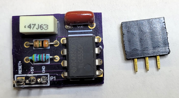
The three pin female socket mounts as illustrated in the three holes at the end of J2.
 +
+
The WD board plugs into the female socket.
Attachments
Images (3)


@gunrunnerjohn - I take it you don't do SMD? A
I do a lot of SMD, this was laid out as a kit so I did it with thru-hole stuff as many people have difficulty with SMD. For this application, there was no benefit to SMD, there's plenty of room for the board inside the DCS-RC where it installs.
I do have a size limit on hand assembled SMD, usually 0603 for resistors and caps. They're still pretty easy to handle. I once screwed up and specified some 0201 resistors on a board, I couldn't even see the little things! It took me forever to build the prototype, and I immediately sent that sucker out for a rework with larger parts!
Most of my products that are sold through Hennings are SMD. Also, most of the stuff I've build for local use here is SMD, only a handful of the projects end up being thru-hole. If it might be offered as a kit, I look at thru-hole. Also, if I'm going to hand assemble a bunch of them, I may consider thru-hole for at least some parts, it's usually quicker to do.
IF you make more of these I will take two of them.
I have a few more in stock. I actually built a few of the "new and improved" model using the 555 timer that requires no calibration, but it works the same as the others. Drop me an email to my profile address and we'll fix you up.
John, interesting comment on the 0603 smd size. With my limited (but growing) smd experience, thats pretty much the smallest size that seems practical. I accidentally ordered a few 0402 resistors a while back, and promptly tossed them out when they arrived.
I was happy to see that all parts for your smart motherboard project are at least 0603, and it went together quite nicely. I finally figured out an smd soldering technique that seems to get the job done with minimal muss and fuss. The only pesky part on that board is the tiny little indicator led, and being polarity sensitive, you need to get it right!
Anyway finally after all your prodding I took the smd plunge, and here we are. It seems to be working! Nice when an old dog can still pick up a new trick or two. ![]()
Rod
Once you get used to handling them, they're not too bad. I don't think you'll ever be quite as fast as with thru-hole, but you can make much smaller boards with more functionality, which is why I took the plunge. Also, nowadays, it's harder and harder to find some functionality in thru-hole parts, everything is going SMD.
Just wondering is there any harm in using a TLC555IP vs the TLC555CP?
John,
Where is the parts BOM for the 555 based version?
Steve
See THIS post.
also I think GRJ just put some assembled versions together check the for sale forum if you wish to go that route
Hi John, I am late to this game, but what if you don't have a DCS commander for your Watchdog timer board?
@mike g. posted:Hi John, I am late to this game, but what if you don't have a DCS commander for your Watchdog timer board?
Then the board would be of no use to you. The DCS Remote Commander generates the WD signal, the add-on board just continually resets it at one second intervals to force the continual generation of the WD.
@gunrunnerjohn posted:Then the board would be of no use to you. The DCS Remote Commander generates the WD signal, the add-on board just continually resets it at one second intervals to force the continual generation of the WD.
so I have the full DCS system and there is nothing for a watchdog system?
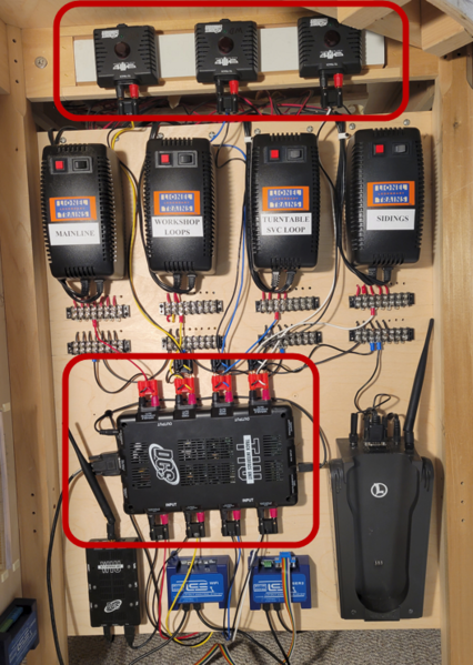
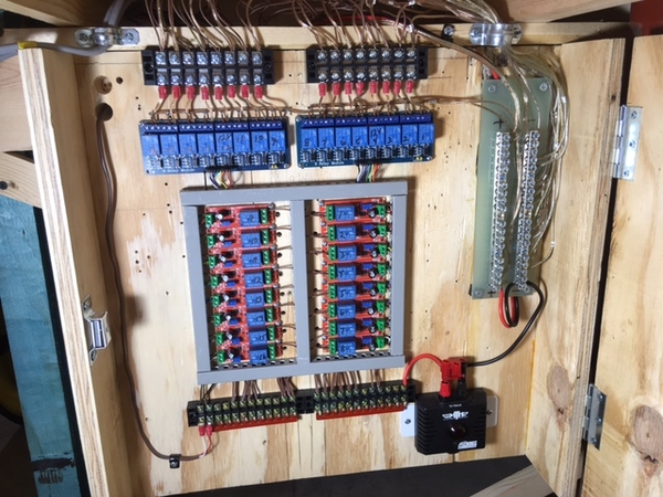
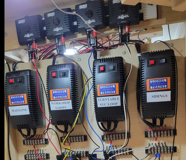
Nope, other than cycling power on the input of the TIU channels. I obviously have the full TIU, but I also have three of the four channels being fed by my WD generator. This allows me to switch individual sidings that are powered by these channels and not have to turn off the entire channel to insure a WD signal to keep the engines silent.
DCS-RC boxes at the top are all equipped with the WD board and service everything but the mainline TIU channel.
Attachments
Images (1)

Thanks John, I will have to research this more. can one just buy the DCS-RC boxes?
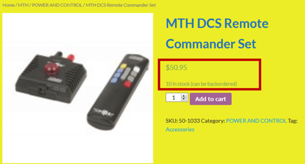
You can buy just the DCS Remote Commander 50-1033. The MTH site shows no dealer stock using "Find It Locally" though I'm not sure this availability info is up-to-date given MTH's evolving business situation.
There was a time a few years back when you could get the DCS-RC for next to nothing on eBay or from an OGR member. Now I see they are selling for more than the $60 MSRP! ![]()
@mike g. posted:Hi John, I am late to this game, but what if you don't have a DCS commander for your Watchdog timer board?
BTW, if searching be sure to use "DCS Remote Commander" and the 50-1033 part number. MTH also made a "DCS Commander" which is a different animal.

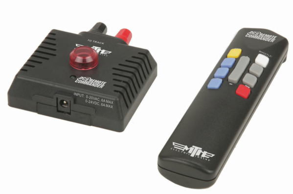
You only need the receiver shown on the left. You don't need the remote. Sometimes you will see an eBay listing for one or the other...though usually it's just the remote for sale.
Attachments
Images (1)

Check this deal if it can be believed they have ten of them. https://www.imperialtrainco.ne...emote-commander-set/
Attachments
Images (1)

@gunrunnerjohn posted:Nope, other than cycling power on the input of the TIU channels. I obviously have the full TIU, but I also have three of the four channels being fed by my WD generator.
...
Seems I've read many threads over the years on guys with a TIU that only partially work, or too old to upgrade, or whatever...and are sitting in a box. So if someone absolutely needs this power-on watchdog function, I wonder if the "next" gadget is some way to re-purpose an unused TIU (or even just an unused TIU channel) in passive mode for the sole purpose of generating the Watchdog?! ![]()
Actually, the thread started out with me doing exactly that. ![]() Go back to the first page of this topic and scroll down, I was trying to come up with a way to do it with a TIU channel when you happened along and came up with the great idea of using the DCS-RC with a reset board.
Go back to the first page of this topic and scroll down, I was trying to come up with a way to do it with a TIU channel when you happened along and came up with the great idea of using the DCS-RC with a reset board. ![]()
@stan2004 posted:Seems I've read many threads over the years on guys with a TIU that only partially work, or too old to upgrade, or whatever...and are sitting in a box. So if someone absolutely needs this power-on watchdog function, I wonder if the "next" gadget is some way to re-purpose an unused TIU (or even just an unused TIU channel) in passive mode for the sole purpose of generating the Watchdog?!
The problem with the TIU is connecting two channels together seems to create issues, I don't know how that would be resolved.
For some reason the DCS-RC in parallel with the output doesn't seem to cause a problem. The only issue so far that's surfaced is the Apple version of the DCS WiFi app has issues adding engines with the WD generator active. However, the Android version here has no issue at all with the WD generator running on the channel.
Stan and John, thanks for the information. so with just 2 sidings that I power on and off can I do that with one DCS box?
@gunrunnerjohn posted:The problem with the TIU is connecting two channels together seems to create issues, I don't know how that would be resolved.
For some reason the DCS-RC in parallel with the output doesn't seem to cause a problem. The only issue so far that's surfaced is the Apple version of the DCS WiFi app has issues adding engines with the WD generator active. However, the Android version here has no issue at all with the WD generator running on the channel.
Of course this is all in the spirit of OGR being a discussion forum. That said ...
I think the trick would be to power up an unused/available TIU channel for a just a few seconds and then remove power....just long enough for the TIU channel to generate its power-on Watchdog.
As briefly discussed early in this thread (which is almost 5 years old!) I'd still push for a "solution" that does not require the user to rotate the switch to the "home" position each time changing the active yard track. So it would be some kind of change detector that then activates a timer that applies track power for just a few seconds to an available TIU channel in passive mode.
@mike g. posted:Stan and John, thanks for the information. so with just 2 sidings that I power on and off can I do that with one DCS box?
Yes, I manage six sidings on one TIU channel, each siding has an individual power switch, all are powered from that single channel. I also have sixteen turntable whisker tracks and my access loop for the turn table on one TIU channel, each whisker track is individually switched when I want to access the engine in that location. The sky is the limit really. Most of the channels will be off and not affecting the DCS signal as a rule.
@stan2004 posted:Of course this is all in the spirit of OGR being a discussion forum. That said ...
I think the trick would be to power up an unused/available TIU channel for a just a few seconds and then remove power....just long enough for the TIU channel to generate its power-on Watchdog.
As briefly discussed early in this thread (which is almost 5 years old!) I'd still push for a "solution" that does not require the user to rotate the switch to the "home" position each time changing the active yard track. So it would be some kind of change detector that then activates a timer that applies track power for just a few seconds to an available TIU channel in passive mode.
You're right Stan, that was also part of that discussion. Remember this diagram? This was an effort to do exactly that, just connect the TIU channel in passive mode when one of the yard tracks was activated. With a break before make rotary switch, the thinking was each track change would break power for long enough to force a reset of the channel and another WD instance.
You scuttled this whole scheme with the clever WD reset board for the DCS-RC, that ended up being such a much better alternative that I abandoned thinking about doing it with a TIU channel. ![]()
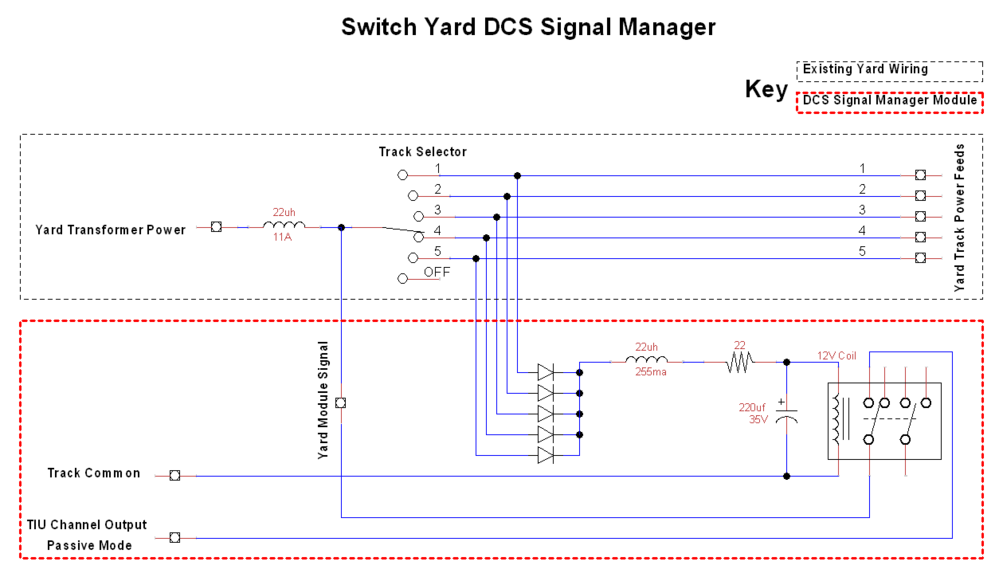
@gunrunnerjohn posted:...With a break before make rotary switch, the thinking was each track change would break power for long enough to force a reset of the channel and another WD instance...
Wow, I can almost remember the discussion after 5 years...yet I had to think hard about what I had for breakfast. ![]()
I'd be surprised if the break-before-make interval is long enough to trigger a new power-on reset. Additionally, the donor TIU channel would then be ON. It is my understanding that later versions of TIU would "spray" Watchdog activity for tens of seconds when a channel is first turned on. So during this time, and to your earlier point, having the passive channel spray watchdog activity for many seconds might interfere with the mainline's TIU channel performing normal DCS control. Hence, I believe the prudent thing to do is to only turn on the Watchdog channel for a few seconds at most.
Putting the cart before the horse, but if we were in a parallel universe where there was no such thing as a DCS-RC...and we were pondering how to use an unused TIU channel...the tactical decision is whether to have a relay clicking On/Off once per second. This would be the PBT or Perpetual Barking TIU. ![]() OR, come up with some "change detector" and timer scheme to briefly passively power the spare TIU channel only when a new yard track, roundhouse spur, siding, or whatever is powered.
OR, come up with some "change detector" and timer scheme to briefly passively power the spare TIU channel only when a new yard track, roundhouse spur, siding, or whatever is powered.
Paralleling the outputs of the TIU is bad news. I'm not sure what would happen with that second channel camped on the output of the powered channel, but my spidey sense tells me that could be trouble. You need to disconnect the second channel from the yard track, it couldn't be sitting in parallel as you'd simply be powering that channel passively from the yard track.
I suppose you could see if you could capacitively couple the channel and then just hit the input with the brief power shot...
My vote is still for the $50 solution I found buying the DCS-RC set in the earlier post. ![]()
Hi Guys I will be back, I am sure with more questions but I have to do more studying on passive mode and other modes! I get so lost into this but onec I understand it I always ask myself why do I make it so hard on myself! LOL
@gunrunnerjohn posted:Paralleling the outputs of the TIU is bad news. I'm not sure what would happen with that second channel camped on the output of the powered channel, but my spidey sense tells me that could be trouble. You need to disconnect the second channel from the yard track, it couldn't be sitting in parallel as you'd simply be powering that channel passively from the yard track.
I suppose you could see if you could capacitively couple the channel and then just hit the input with the brief power shot...
My vote is still for the $50 solution I found buying the DCS-RC set in the earlier post.
John what is the DCS-RC you are referring to?
Attachments
Images (1)

So maybe I missed it in this 5 years worth of posts but does the same issue exist for tmcc/legacy with yard and whisker tracks? I run both tmcc/legacy and dcs. Thanks.
No, TMCC/Legacy doesn't have the same design, thus that signal propagation is much different. It's not to say you'll never have issues with TMCC/Legacy signals, but they are typically manifested with larger layouts, and especially multi-level layouts. TMCC/Legacy also doesn't have the concept of a watchdog signal, the TMCC signal carrier is constant on the rails.
Thanks John. I need to understand tmcc/legacy better. Wish there was something like the dcs book for it! Have I missed that?
And just picked up a Remote Commander yesterday, going to work on the 555 circuit!
@Dougklink posted:Thanks John. I need to understand tmcc/legacy better. Wish there was something like the dcs book for it! Have I missed that?
It's so simple even a caveman could use it. ![]()
![]()
@Dougklink posted:Thanks John. I need to understand tmcc/legacy better. Wish there was something like the dcs book for it! Have I missed that?
Not sure these are as detailed as Barry's DCS book, but here is something for TMCC/Legacy - Book & DVDs from TM Books.
Might be worth a look?
Direct link above didn't go directly to the items. From the above link search for - Modern O Gauge Remote Control at the TM Books site.
Thanks for the lead!
Just ran across this post so I'm a little late to the party.
I've had similar problems to what GRJ had experienced on his club layout, but my layout configuration is a little different. There are seven sidings scattered about that may have Legacy, TMCC or MTH DCS engines stored and when activated via relays are powered from the mainlines (1 & 2) using two Lionel PH180's. In other words, I do not have a separate power feed to the sidings.
There is a single TIU powered in Passive mode using Fixed 1 Output, which is currently the only output in use. Also, since I do not own a DCS-RC unit (and they have obviously become more scarce than hen's teeth) I'm looking for a different solution.
In one of Barry Broskowitz replies he stated "Actually, the watch dog is issued any time the voltage at a TIU channel output port changes from 0 to any greater value."
Does anyone know if the watchdog is issued across all the outputs when a single output changes? For example, a voltage change on Fixed 2 would also trigger the watchdog on Fixed 1.
Thanks,
Barry
I believe it only comes out on the channel that had the voltage change. I just tried it on my bench TIU, and a voltage change on the variable channel did not trigger a WD on the fixed channels.
Thanks GRJ that was my fear! But that would have made life to easy of course. Now I need to come up with plan B, then probably plan C, then .....
Thanks again, I truly appreciate you bench testing plan A.
Barry
@barnun posted:... There are seven sidings scattered about that may have Legacy, TMCC or MTH DCS engines stored and when activated via relays are powered from the mainlines (1 & 2) using two Lionel PH180's. In other words, I do not have a separate power feed to the sidings.
There is a single TIU powered in Passive mode using Fixed 1 Output, which is currently the only output in use. Also, since I do not own a DCS-RC unit (and they have obviously become more scarce than hen's teeth) I'm looking for a different solution.
1. So there are seven relays that switch power. How are the relays controlled (e.g., by an AIU)?
2. Do you ever need more than one siding on at a given time?
If the DCS-RC method is no longer a practical option, why not the approach GRJ proposed in the first post of this thread (over 5 years ago!). In other words every time you turn on a siding, you momentarily remove power from the passively powered TIU channel to use the TIU's watchdog. Depending on answers to above 2 questions, there might be a way for the proverbial man-behind-the-curtain to do it transparently.
@stan2004 posted:In other words every time you turn on a siding, you momentarily remove power from the passively powered TIU channel to use the TIU's watchdog.
That is my plan for 3 or 4 sidings that I'll use to park engines. I have the relays for turning siding power on and off. I have two staging tracks that I turn power off now so the EOTs don't sit blinking all the time. I'm thinking of wiring in a time delay relay that will turn TIU channel power off when I select and engine siding and the delay relay will turn the channel power back on after a few seconds. It means dedicating a TIU channel to the engine parks but I have two not being used.
I keep watching for RC boards to show up on the parts site but I doubt they ever will.
I'm using a rotary switch to control yard power. I select the lane and push a button to turn yard power on and off. I use inexpensive electronically latching relays to carry the track power. When a different lane is selected, power is automatically turned off on the previously selected lane so only one lane can be powered at a time. I haven't worked the WD timer issue yet.
@stan2004 posted:1. So there are seven relays that switch power. How are the relays controlled (e.g., by an AIU)?
2. Do you ever need more than one siding on at a given time?
If the DCS-RC method is no longer a practical option, why not the approach GRJ proposed in the first post of this thread (over 5 years ago!). In other words every time you turn on a siding, you momentarily remove power from the passively powered TIU channel to use the TIU's watchdog. Depending on answers to above 2 questions, there might be a way for the proverbial man-behind-the-curtain to do it transparently.
Stan,
The relays are controlled by Arduino Microcontrollers via an NRF24L01+ 2.4gHz radio network, seven slave nodes controlled by a single Master. The sidings are located on module 1 with 2 spur sidings, 1 spur siding which spans modules 4 & 5 and module 7 (with 4 yard sidings). The Master is co-located with the TIU & WIU, more often than not multiple sidings would be powering on / off during a session.
My original thought was if the TIU issued the watchdog across all outputs when one was changed, problem solved and the most elegant solution. Simply toggle a small voltage change on the currently unused Fixed 2. GRJ's testing proved that is not a viable option.
For now I'm thinking my options are to 1. toggle Fixed 1 off and back on for a brief period of time, something in the 1 second ballpark or as brief as it can be so that the watchdog is triggered. Just not sure what impact that will have on running DCS locomotives. 2. Bridge Fixed 2 across Fixed 1 for a brief period of time, same as option 1. In essence using Fixed 2 as the DCS-RC module. Again, just not sure what impact that will have on running DCS locomotives.
Thanks,
Barry
Here's my two cents worth. I have a nine stall roundhouse and seven whisker tracks around my turn table. I used two 12v 8up relay banks for powering these tracks thru the accessory ports of two AIU's. When I activate a stall/whisker with my remote it also turns on one of these inexpensive (I got these for $1.20 ea.) timer relays and powers up the DCS-RC for whatever time I have the timer relay set for (about 4 to 6 seconds). Here is a pic of my setup.
Attachments
Images (1)

I just have the DCS-RC running continuously on the TIU channel that controls all my siding tracks, 14 in total. Each track is independently switched, and the DCS-RC in continually hammering out it's WD, so engines come up dark and silent, job done.
In point of fact, I have four DCS-RC WD boxes, one for each TIU output, all my tracks get the treatment.
Attachments
Images (1)

@milwrd posted:Here's my two cents worth. I have a nine stall roundhouse and seven whisker tracks around my turn table. I used two 12v 8up relay banks for powering these tracks thru the accessory ports of two AIU's. When I activate a stall/whisker with my remote it also turns on one of these inexpensive (I got these for $1.20 ea.) timer relays and powers up the DCS-RC for whatever time I have the timer relay set for (about 4 to 6 seconds). Here is a pic of my setup.
milwrd, Nice setup, very very tidy!!
@gunrunnerjohn posted:I just have the DCS-RC running continuously on the TIU channel that controls all my siding tracks, 14 in total. Each track is independently switched, and the DCS-RC in continually hammering out it's WD, so engines come up dark and silent, job done.
In point of fact, I have four DCS-RC WD boxes, one for each TIU output, all my tracks get the treatment.
GRJ, makes perfect sense and great setup. May I read your response to infer that your gut says bridging Fixed 2 to Fixed 1 briefly may be the simplest solution?
Dan, Steve and all, thanks for the replies so far.
Barry
@barnun posted:GRJ, makes perfect sense and great setup. May I read your response to infer that your gut says bridging Fixed 2 to Fixed 1 briefly may be the simplest solution?
NO! You will only cause problems connecting TIU outputs, that's a giant no-no!
@gunrunnerjohn posted:NO! You will only cause problems connecting TIU outputs, that's a giant no-no!
As always, thanks GRJ!
Well, so much for plan B ... on to plan C (or D or E ....). Seems like the remaining options are to toggle Fixed 1 off & on or attempt to locate a DCS-RC.
Barry
I've seen some RC's lately at swap meets. Denver was the last one.
Just checked eBay and the most recent actual sales show a used DCS-RC for $30 buy-it-now which seems reasonable. A new unit, which includes the handheld remote (albeit unneeded for this application), went for $200. There are a couple sellers actively offering new DCS-RC for a whopping $250! Yikes. It wasn't that long ago guys on OGR were giving away (just pay shipping) unused/unneeded DCS-RC units as they were included in MTH Starter Sets.

Attachments
Images (1)

@stan2004 posted:Just checked eBay and the most recent actual sales show a used DCS-RC for $30 buy-it-now which seems reasonable. A new unit, which includes the handheld remote (albeit unneeded for this application), went for $200. There are a couple sellers actively offering new DCS-RC for a whopping $250! Yikes. It wasn't that long ago guys on OGR were giving away (just pay shipping) unused/unneeded DCS-RC units as they were included in MTH Starter Sets.
Stan,
Thanks for checking! I did see the new ones going for exorbitant prices and regarding the OGR units as usual I'm a day late and dollar short. Unfortunately, I could not find any available via my normal commercial outlets. Petersen Supply did have a web page showing one in stock, but it was an out-of-date cached web page according to the exceptionally pleasant lady I spoke with at Petersen's. I'll post a 'wanted to buy' here on OGR and put some feelers out to the normal 'train collection recycling' businesses along with a recurring search on eBay. Surely one will turn up at some point. Thanks again.
Barry
@barnun posted:...
The relays are controlled by Arduino Microcontrollers via an NRF24L01+ 2.4gHz radio network, seven slave nodes controlled by a single Master. The sidings are located on module 1 with 2 spur sidings, 1 spur siding which spans modules 4 & 5 and module 7 (with 4 yard sidings). The Master is co-located with the TIU & WIU, more often than not multiple sidings would be powering on / off during a session.
But who/what controls the Master? By "co-located" is this just physical location or is there any "software" interaction between the 2.4 GHz radio network and DCS... for example at the Wi-Fi level. Note that to turn on a newly powered engine (e.g., on a siding) in the silent state and in Command mode, you don't need to generate the Watchdog packet itself. ANY DCS activity during the first few seconds will tell a newly powered DCS engine to start up silent and in Command mode. The Watchdog is essentially a benign placeholder command that doesn't do anything (doesn't change speed, doesn't blow horn, etc.) other than tell a newly powered engine that this is a Command control environment so be quiet and wait for further instructions.
This idea of "manually" creating DCS activity during the first few seconds of turning on a siding was discussed early on in the thread - some 5 years ago! It just seems that with all those Arduino's there ought to be some way to "hack" into the WIU to tell the TIU to issue some benign DCS activity whenever a new siding is powered.
Another scheme discussed early on required Arduino-type smarts (which you have). Why not have the Arduino generate the watchdog or whatever suitable DCS activity and put it on the track. There are issues with this which you can review but I regurgitate it for the sake of completeness or potentially stimulate additional what-ifs.
But I think your Plan B is the way to go - since your Master knows when it is turning on a siding, simply add a relay to momentarily interrupt the passively applied power to Fixed 1. Since the TIU is passively powered, the engines will not see the power interruption so they are none the wiser. It's only if the power interruption somehow confuses the TIU such as whatever information it has about Active Engines or whatever. But this momentary power-interruption method was what GRJ proposed in his original post so I think the most logical next step.
@stan2004 posted:But who/what controls the Master? By "co-located" is this just physical location or is there any "software" interaction between the 2.4 GHz radio network and DCS... for example at the Wi-Fi level. Note that to turn on a newly powered engine (e.g., on a siding) in the silent state and in Command mode, you don't need to generate the Watchdog packet itself. ANY DCS activity during the first few seconds will tell a newly powered DCS engine to start up silent and in Command mode. The Watchdog is essentially a benign placeholder command that doesn't do anything (doesn't change speed, doesn't blow horn, etc.) other than tell a newly powered engine that this is a Command control environment so be quiet and wait for further instructions.
This idea of "manually" creating DCS activity during the first few seconds of turning on a siding was discussed early on in the thread - some 5 years ago! It just seems that with all those Arduino's there ought to be some way to "hack" into the WIU to tell the TIU to issue some benign DCS activity whenever a new siding is powered.
Another scheme discussed early on required Arduino-type smarts (which you have). Why not have the Arduino generate the watchdog or whatever suitable DCS activity and put it on the track. There are issues with this which you can review but I regurgitate it for the sake of completeness or potentially stimulate additional what-ifs.
But I think your Plan B is the way to go - since your Master knows when it is turning on a siding, simply add a relay to momentarily interrupt the passively applied power to Fixed 1. Since the TIU is passively powered, the engines will not see the power interruption so they are none the wiser. It's only if the power interruption somehow confuses the TIU such as whatever information it has about Active Engines or whatever. But this momentary power-interruption method was what GRJ proposed in his original post so I think the most logical next step.
Stan,
Wow, a lot to think about and digest. I'll start with the Master Arduino. It's directives come from a keypad mounted on the control console or via Bluetooth from an Android tablet. When I first built the layout there were four rows with five columns of the Atlas 2 position switches wired to the switches on the layout along with accessories and sidings. Talk about a wad of wires. So if I wanted to throw Node 1 Switch 1 on the mainline, I'd toggle switch R1C1. Now I input 11 on the keypad or tablet and press send. It was the easiest way I could think of not having to re-learn a new number schema.
'Co-located' references physical location, both the Master and TIU reside in the same cavity at the master console with the WIU on top. So physical wiring / interconnection is not a problem. The main point of converting to wireless was to minimize the wired connections between the console and the layout.
There is currently no direct interaction between the radios and DCS. I've only very recently started to dip my toes in the Arduino / Legacy pond and have a very large amount of knowledge to learn. One place I fall really short right now would be with the WIU and how it interfaces with the tablet. From everything I've read on the Forum it seems MTH never released the protocols for DCS unlike Lionel has for TMCC / Legacy. Needless to say a 'hack' between the Master and the WIU or TIU would be the perfect solution. Just not sure how I get to there from here.
I tend to agree with your assessment regarding Plan B. Since I'm still in the process of converting the layout to wireless, it's not really operational at the moment. I will try to come up with some kind of test bed to check on the Fixed 1 momentary interruption. I think where my brain is at regards the timing around an engine on the inactive list being powered up, moving to the active list and some form of DCS command being issued for that specific locomotive.
Your and John's PWB is also an attractive solution.
As always Stan, I appreciate your (and all on the Forum) input.
Thanks, Barry
OK, Plan C Revision 1 Addendum 1. ![]()
Since I now have full ownership of and legal rights to a DCS-RC unit and a PWB is on the way from GRJ, can anyone think of a good reason the following would not work instead of adding the PWB board.
1. Wire the DCS-RC unit to the TIU Fixed 1 output in passive mode.
2. Wire a ground between the Arduino MC and the DCS-RC unit ground pin.
3. Wire a connection between an Arduino MC Output Pin (set normally High) and the DCS-RC unit Reset Pin.
4. Whenever the Arduino MC throws a relay to power any of the sidings the next line of code drives the Output Pin to ground for 'x' amount of time for say 3 repetitions. Theoretically causing the DCS-RC to reset and issue it's watchdog 3 times.
I do understand that as currently deployed on numerous layouts the PWB resets once a second and the watchdog does not cause any problems. My thoughts were, 1. it should reduce the digital traffic on the control channel and 2. Allows full control of the watchdog timing.
I now control the vertical, I now control the horizontal, do not attempt to adjust your DCS-RC. (for those of you old enough to remember 'The Outer Limits' of which I more than qualify).
Just thought I'd throw this out to the forum brain trust.
Barry
Oh. You mean you want to know the reason? ![]()
The track ground (black banana jack) on the DCS-RC is NOT the same as the internal digital signal ground as used by the microcontroller chip. I confirmed this with a DMM continuity measurement.

By peeking under the hood, there is a bridge rectifier which converts the track voltage (typically AC but can be DC) and converts it to DC for use by the digital electronics. So the track voltage "ground" and the internal digital signal "ground" are not the same. The signal transformer also kind-of sort-of corroborates this as this is in all likelihood how the high-frequency DCS watchdog signal is coupled onto the track voltage coming from a circuit with a different ground.
Not to worry. Just hook up a 25 cent DC-optocoupler and a 5 cent resistor between your Arduino output pin and the DCS-RC. If not familiar with this interconnection technique, I can draw you a diagram/schematic. If you don't have these parts lying around, it will be annoying since the shipping will be 10 times the cost of the components. ![]()
Actually, you could connect the Arduino ground to the DCS-RC internal ground rather than to the DCS-RC track ground. You would not need an optocoupler and could directly connect the Arduino output pin to the DCS-RC reset pin. Everyone is entitled to their opinion; my opinion is you should NOT do it this way...please use the optocoupler method.
But moving on. So every time you trigger a relay to power up a previously unpowered siding, issue a reset pulse to the DCS-RC. The pulse should be, say, 0.1 seconds long. Do this 3 times (or however many you want) with each pulse separated by 1 second. Note from earlier discussion that the DCS-RC sends out the Watchdog burst about 3/4 second after you issue the reset pulse. The duration of the Watchdog burst is very short - less than 0.1 seconds IIRC.
Attachments
Images (1)

@stan2004 posted:I can.
LOL.
Stan,
It was my intention to hook up to the signal ground and not the track ground using the pins you and GRJ use to power your reset board. Obviously, I was less than clear in the previous post. But, I really really like the idea of the optocoupler. Should anything happen in the DCS-RC unit (albeit unlikely) it would be much better to fry an .89 cent optocoupler as opposed to an $8 MC, and no waiting or shipping cost as I have a number of the pre-fab units on hand. I should have thought of that earlier.
Curious as to the logic behind using the Track ground as opposed to the Signal ground. Your thoughts?
I truly appreciate the timing synopsis! Should make writing the code that much easier, my current view is when activating a spur or yard siding is to set a variable (most likely WDT) to the number of times I wish to reset the DSC-RC and decrement it by one each time the MC issues the reset command till it reads 0. Provides an easy and convenient method of controlling the desired number of resets and the main loop runs quickly as the only time it branches to the watchdog subroutine is when WDT => 1.
Also, on a different topic .... in your spare time could you possibly start working on a Warp Drive?
Thanks, Barry
I'm at a loss as to why not just hook up the WD Generator and let it run. I adhere to the K.I.S.S. principle whenever possible. Why are you making a simple job complicated?
@gunrunnerjohn posted:Why are you making a simple job complicated?
GRJ,
Good morning, the most likely answer is 'a minor character flaw'. ![]()
Personally I don't really view this as being much more complex, with either option I still have to open the case, solder in a header on the DCS-RC board and either insert the PBW or two wires. The coding is a nit and pretty much already good to go. To be honest I really have not yet decided on which way I want to go, kinda' reviewing options.
On the PBW plus side, known working good reliable solution for todays environment.
Simply my opinion, on the PBW minus side is the continuous traffic on the control channel and more limited ability to modify the hardware timing parameters should the environment change in the future.
On the MC plus side, reduced control channel traffic and a more easily implemented range of software timing solutions should the environment change tomorrow. Plus, sometimes I enjoy a good challenge, hope that helps 'splain where my head's at.
I'm also hoping to receive your & Stan's PBW board today.
Barry
@barnun posted:...
3. Wire a connection between an Arduino MC Output Pin (set normally High) and the DCS-RC unit Reset Pin....
@barnun posted:
...But, I really really like the idea of the optocoupler. Should anything happen in the DCS-RC unit (albeit unlikely) it would be much better to fry an .89 cent optocoupler as opposed to an $8 MC, and no waiting or shipping cost as I have a number of the pre-fab units on hand. I should have thought of that earlier.
Curious as to the logic behind using the Track ground as opposed to the Signal ground. Your thoughts?
...
In thinking about years of OGR Electrical Forum discussions, there's been interchangeable use of terms signal ground, track ground, earth ground, outer-rail ground, trigger ground, chassis ground, logic ground, local ground, ground coffee (OK, maybe not that one)...but you get the idea. Ground was what you connect the black probe of a meter to and the black terminal of a transformer. I believe there are many guys who simply lump all grounds together as being one-and-the-same sort of like a universal "common." Obviously you are not of that school of thought!
Anyway, to further glaze over more eyes, if directly hooking up an Arduino output pin to an active-low microcontroller reset line (as in the DCS-RC), I would set the Arduino output pin to "normally Tri-state" rather than "normally High." Especially in this case where you're driving an unknown environment. You will see that the PBW board uses an open-collector transistor to pull down the DCS-RC reset line. So this is equivalent to going "tri-state" except when generating the reset pulse. This allows other elements of the unknown circuit to drive the reset line too - and again we have no schematics so it would be "rude" to assume you can drive the signal HIGH when you aren't using it! Additionally, microcontroller circuits can multiplex the active-low reset pin to take on other circuit functions which would of course be compromised if some interloping circuit drives the pin HIGH. OK, I think I made my point. LOL.
So all this goes away with an opto-coupler. You can drive the Arduino output pin HIGH and LOW rather than mucking around with driving the output pin TRI-STATE and LOW. My only concern is what you mean by a "pre-fab" unit. Is this some kind of opto-coupler that might buffer (drive) the isolated output HIGH. I was assuming a generic DC opto-coupler which has an "open-collector" transistor as its output pins and thereby would only turn on when the Arduino outputs the short reset pulse.
And to your point about frying an 89 cent optocoupler instead of whatever, I think the last thing you want to roll the dice on is frying the DCS-RC custom-programmed microcontroller chip which is surely irreplaceable. The galvanic isolation of the opto-coupler insures there is no current path from an external source and each circuit maintains its own "ground." That is, the DCS-RC signal ground is effectively one-diode voltage away from the nasty track voltage ground. Connecting this to the Arduino ground is like shackling a ball-and-chain to your leg... in my opinion of course! ![]()
@stan2004 posted:'interchangeable use of terms signal ground, track ground, earth ground, outer-rail ground, trigger ground, chassis ground, logic ground, local ground, ground coffee'
LOL ... you forgot 'hallowed ground and ground down to a bloody pulp.
'Especially in this case where you're driving an unknown environment.' 'OK, I think I made my point. LOL.'
Succinctly, with great clarity and relevance!
'I was assuming a generic DC opto-coupler which has an "open-collector" transistor as its output pins and thereby would only turn on when the Arduino outputs the short reset pulse.'
I'm assuming that's why I didn't see any triode tubes
. My experience to date with the 'pre-fab' optocouplers is the output duplicates the input. If it receives a high (1) it outputs a high (1), if it receives a low (0) it outputs a low (0). But I can easily test that. Tri-State in Arduino speak would be : pinMode((pin x), INPUT_PULLUP). I will say previously I've only set the pin's pinMode during setup, but I see no reason (yet) that it couldn't be toggled (from Input to Output do a digitalWrite and back to Input) during a subroutine. Again, an easy test (easy to say as I sit here not having tried that yet).
Just did a little research and according to :
https://www.baldengineer.com/w...pinmode-and-why.html 'Starting with IDE 1.0.1, if pinMode() is called with INPUT, the internal pull-up resistor is explicitly disabled. However, when pinMode() is called with INPUT_PULLUP, the pull-up will be enabled. You can still override the state of the pin after pinMode() has been called by using digitalWrite.'That sounds like I may not have to change the pinMode, simply do a digitalWrite. But, I'm never that lucky.
'frying the DCS-RC custom-programmed microcontroller chip which is surely irreplaceable.' ' in my opinion of course!
'
Which is spot on and always valued! Thanks, Barry
@barnun posted:...My experience to date with the 'pre-fab' optocouplers is the output duplicates the input. If it receives a high (1) it outputs a high (1), if it receives a low (0) it outputs a low (0).
And if it receives a tri-state will it output a tri-state? That would be a sublime circuit design on several levels.
Stan, these are the units I have on hand. They are listed as ILD213T. Data sheet can be found here:
https://studylib.net/doc/18675242/ild213t-datasheet

Attachments
Images (1)

OK. I'm 99% confident it will work in this specific application but there are many flag-on-the-fields to make one scratch their head or other body parts. ![]()
I pulled the above from an eBay listing and I realize all the sellers are copying the verbiage from another listing etc. etc.
But a TTL micro? Yeah, there were a few "TTL" micros back in the day but they would burn so much power as to make them impractical except for maybe some military or esoteric applications. For example, it appears there's a 220 Ohm resistor on the input opto diode. So if using a 5V Arduino, and driving the DL213 ~1.2V opto led, that's a (5V-1.2V)/220 Ohm = 17 mA drive current. Are you kidding me?! Can an Arduino even source that much current on an output pin? Well, even if it can, that's just insane...when the output of the module has a 10K pullup resistor which means that if it is indeed mimic'ing (i.e., High input -> High output) the opto input, it can only source, say, 5V/10K Ohms = 0.5 mA. That kind of current-transfer-ratio doesn't pass the laugh test. Either that or maybe the jokes on me? ![]()
Well, my concern was to insert galvanic isolation between your Arduino and the DCS-RC, and you get that so it is what it is.
Attachments
Images (1)
Sorry to be in this camp, but I'm still of the opinion that we're searching for the answer to a question that shouldn't have been asked. The additional "traffic" added by the WD generator is trivial, and installing it is dead simple, just connected it to the TIU output. It's still a mystery to me why all the work to accomplish so little.
@gunrunnerjohn posted:Sorry to be in this camp, but I'm still of the opinion that we're searching for the answer to a question that shouldn't have been asked. The additional "traffic" added by the WD generator is trivial, and installing it is dead simple, just connected it to the TIU output. It's still a mystery to me why all the work to accomplish so little.
So in addition to being the MacGyver of train repairs you are an Existential Philosopher too! ![]()
@stan2004 posted:= 17 mA drive current. Are you kidding me?! Can an Arduino even source that much current on an output pin?
Gentlemen, good morning.
Stan, although I've never measured the current, my understanding is the Arduino can source up to 20 mA on a pin safely (40 mA tops with the Mega 2560). Up to the current limit of the power supply on the board when using multiple pins simultaneously which somewhere in the back of my little pea brain says 200 mA. Submitted in the spirit of 'just fyi'.
@gunrunnerjohn posted:Sorry to be in this camp, but I'm still of the opinion that we're searching for the answer to a question that shouldn't have been asked.
GRJ, in my opinion there is nothing to be sorry about. I would only disagree with 'shouldn't have been asked.' This is all kinda' moot as I've decided to just use the PWB as is. But, if in the future I need to address a completely different situation with a similar solution it is documented here and I've considered this as a learning opportunity.
As always, my thanks to everyone. Barry
In regard to the Arduino port current capability, I looked around and found this.

Attachments
Images (1)
@gunrunnerjohn posted:NO! You will only cause problems connecting TIU outputs, that's a giant no-no!
Can you elaborate on this? What is it about hooking two TIU outputs together is a no-no?
For example, would powering the donor TIU channel with a separate power supply and then capacitively coupling the two channels help so that "only" the high-frequency DCS Watchdog signal is injected into the yard track?
Does this apply if the TIU output is from a completely separate TIU? That is, someone may have an old version or partially functional TIU and use it as a Watchdog generator. On eBay now the cheapest you can get a USED DCS-RC is $130 plus shipping. New ones go for $200 and up! At those prices kind of begs the question, why not or what would it take to apply an unused TIU channel?! ![]()
Poking my head into this thread, is this still the best way to get the DCS signal to a yard/siding on toggled power, or has MTH stopped dragging their feet and given a way to shoot the magic WD signal from the TIU whenever I sneeze? (Or on the flip side if someone has figured out how to force the TIU to send the magic signal)
@SirCaptain posted:Poking my head into this thread, is this still the best way to get the DCS signal to a yard/siding on toggled power, or has MTH stopped dragging their feet and given a way to shoot the magic WD signal from the TIU whenever I sneeze? (Or on the flip side if someone has figured out how to force the TIU to send the magic signal)
Look at the first post in this thread, that how I do it!
GRJ, have you heard anything on when MTH Parts might get the backordered remote commander boards? I did put my email in for a notification… Also tell me you still have or will do another run of your “perpetual barker” board?
Thanks
Jeff
@gunrunnerjohn posted:Look at the first post in this thread, that how I do it!
On one hand, great to hear this is still working well. On the other hand, shame on MTH for not releasing some kind of tool to DIY this.
Also, slightly scared to solder the pins onto the RC ... seeing as I have exactly one and it cost and arm and a leg to get a hold of on the Bay of E's. But this is what I bought it for, no sense in staring at it on the project table hoping it will magically solder itself.
@Central Terminal Jeff posted:GRJ, have you heard anything on when MTH Parts might get the backordered remote commander boards? I did put my email in for a notification… Also tell me you still have or will do another run of your “perpetual barker” board?
Nope, however my sense is that it's likely that "never" is the projected resupply. I can't imagine they're still manufacturing those boards, so I suspect that what was in stock was it.
@SirCaptain posted:On one hand, great to hear this is still working well. On the other hand, shame on MTH for not releasing some kind of tool to DIY this.
Given how easy it would have been for them to just add that to the TIU software, it is a shame that they didn't solve this problem.
@SirCaptain posted:Also, slightly scared to solder the pins onto the RC ... seeing as I have exactly one and it cost and arm and a leg to get a hold of on the Bay of E's. But this is what I bought it for, no sense in staring at it on the project table hoping it will magically solder itself.
Well, if it's really a problem, send it to me and I'll solder them. ![]()
Biting the bullet, waiting on my digikey, mouser, and oshpark orders to come in. I figure I'll try and solder the board first, if I don't screw that up then soldering a 3 pin header on an unreplaceable board should be a walk in the park. Happy to see all this was worked out by you guys way before I even considered dead power yards.
I hear that MTH is getting more DCS Remote Commanders produced, that's good news for the folks that want the watchdog generator on their layout. Mine are happily generating watchdog signals on all my tracks. ![]()

Attachments
Images (1)

Well that's good news to hear at least, although you'd think it would be cheaper to just... Add a constant TIU watchdog signal output via a software upgrade (TIU v7 anyone?). But who knows, maybe they are doing another batch to help with control system sales.
@gunrunnerjohn Can you add a BOM to the first post? I found another thread with a BOM list... but now that I have it all in front of me it looks like I may be missing something.
Here's the thread I found the BOM originally: https://ogrforum.ogaugerr.com/topic/pbw-needed?reply=100540307597091066#100540307597091066
However it appears this WD gen rev uses a different PCB layout/parts from the post above
Edit: I'm just now realizing that the BOM on that thread is for an older 555 revision of the board. I see a Rev 2 on the bottom of this board so that explains the wildly different PCB layouts
Here's the BOM for your version, that was the first generation of the design. The 555 version was the later version, it required no calibration.

Attachments
Images (1)

I have a few kits left for the 555 version of the PBW. Send me an email if interested, email is in my profile.
It sure would be nice of MTH did resume production of the remote commanders.
@gunrunnerjohn posted:Here's the BOM for your version, that was the first generation of the design. The 555 version was the later version, it required no calibration.
Ahhh gotcha, well good thing these pcb's were extremely cheap lol
@rtr12 posted:I have a few kits left for the 555 version of the PBW. Send me an email if interested, email is in my profile.
It sure would be nice of MTH did resume production of the remote commanders.
shot an email over
I see that the DCS Remote Commander is in stock in a number of places again. If anyone was waiting to make some Watchdog generators for their layout, now's a good time to get the required DCS-RC.
Add Reply
Sign In To Reply
