
After looking at older posts, I could not find a solution to this issue, so here goes.

I have an early Santa Fe F3 20-2153-1 and due to the passenger consist, just having the one powered unit is not enough to pull the 7 aluminum KLine Hi Level cars. I have added a powered B, 20-2151-4 to the consist ABBA. The issue is that when powering up, the engines do not sync up. I am using a Z4000 and the Z4001 remote. Track is Gargraves. Any suggestions as to why? Is it still too heavy even for 4 motors? And yes, I have already changed out the neoprene tires.

Original Post

Replies sorted oldest to newest

@BRicch posted:

After looking at older posts, I could not find a solution to this issue, so here goes.

I have an early Santa Fe F3 20-2153-1 and due to the passenger consist, just having the one powered unit is not enough to pull the 7 aluminum KLine Hi Level cars. I have added a powered B, 20-2151-4 to the consist ABBA. The issue is that when powering up, the engines do not sync up. I am using a Z4000 and the Z4001 remote. Track is Gargraves. Any suggestions as to why? Is it still too heavy even for 4 motors? And yes, I have already changed out the neoprene tires.

This is because one engine is a PS1 and the OTHER is a DCRU.

So follow the additional detailed instructions that came with the DCRU powered B unit.

https://mthtrains.com/sites/de...ction/20dl12727i.pdf

DCRU® REVERSE UNIT
As mentioned in the Basic Operating section, the engine is controlled by a
DCRU® reverse unit that contains the standard forward-neutral-reverse
states found on most reverse units. However, when power is first applied to
the track, the reverse unit begins in RESET or what seems like a neutral
state. Power must be interrupted again to get the locomotive to enter the
forward state. The system will enter RESET whenever power to the track is
off for three or more seconds. NEUTRAL should be referred to as the state
between Forward and Reverse.
Because the ProtoSound® system or DCRU® reverse unit found in your
powered MTH F-3 A unit is not directly connected to the DCRU® unit in
your powered F-3 B-Unit, you
must cycle the power on and off
slowly to maintain proper
synchronization between each
powered unit’s reverse unit. If
the units should become
unsynchronized, simply shut
down power for three or more
seconds. Upon repowering, each
unit should come up in RESET. If you choose to operate your existing F-3
A units in a “locked-out” state, a lockout switch on the powered F-3 B-Unit
has been provided so that you can manually “lock-out” the B-Unit in the
same direction the powered A Units are configured.

Also, this is why MTH PS1 dual powered A units from the factory use the tether system and provide forward and reverse control to the DCRU in the rear unit to "slave" off the front unit. When you do this wiring, again, the DCRU board F-N-R logic function is disconnected, and now it's basically commanded F-N-R across this 3 wire tether system.

I would not recommend this for a novice- but it's just 3 wires, between the PS1 board in the front engine, to the DCRU board in the rear trailing engine

PS1 slave wiring

Attachments

Images (1)
  • PS1 slave wiring
@BRicch posted:

So it sounds like I’m being too aggressive when powering up the engines.

No.  You're being tooo aggressive in your assumptions that these two locomotives will somehow synchronize themselves, or are easy to synchronize manually.

As we all know here on the forum MTH's PS1 locomotives are seriously finicky to operate.  Fortunately DCRU equipped units are usually straightforward. 

As Vernon as mentioned, these two quite-different units will not cooperate -- least not without some extra, perhaps seriously extra, effort.  He's pointed to two possibilities:

  1. Your 'B' unit's instruction sheet (DCRU Control System) may list directions for setting up Its forward and reverse sequencing to match your 'A' Unit (PS-1 Control System).  He's provided a couple of paragraphs (see above) from a typical DCRU instruction sheet for getting it to behave in this situation.  This is an example of needing additional finicky detail for your DCRU unit to get it to work smoothly with the PS1 unit.  If you're not patient with this approach it could make things worse.  I could easily see how you might say you're being too aggressive (with the throttle) and so it's not working.
  2. You may also, or more likely in place of the above, need to install a wire harness (tether) between your two units in order for the two to work together.  Vernon has also described this option. It will be three wires connecting the two units.  Since MTH developed this method and it has apparently been used successfully in in multiple unit arrangements we might consider this the preferred approach.  Yet, you may not be comfortable constructing such a tether harness.

Are you comfortable attempting this second one above, if the first one doesn't seem to work?

If you're not I would suggest finding an experienced service technician to install the tether and address this problem.

Mike

Mike, though I’m a bit hesitant at touching electronics for fear of screwing things further, the pictures sent look pretty straightforward. I will try this and report back on my success.

one last comment on this particular consist, there are a total of 7 cars, all with lighting plus the engine set with a total of 4 motors. The reading on the transformer shows 19v even as it’s starting to move. Am I asking for more issues by keeping this as is?

Unfortunately I can’t answer that. What I can say is that running other trains on the same track I see 15-16 but those are shorter passenger sets, still Kline aluminum ones, but not the hi level cars. This one set is the longest and the heaviest. By adding two cars, I needed to add a second engine which is how I got to my original posting.

@BRicch posted:

When I had 5 cars and the ABA with only one of the units being powered it would start moving at 12. But adding two more cars and also the powered B brings it up to 19 as it starts to move slowly. It was at 22 when I was finally able to get the engines to sync up.

How many Amps if you know the voltage? That just seems a lot of power going somewhere- likely in the form of heat.

My guess, something is getting way hot somewhere.

John, when using the Z4001 remote the Z4000 only shows the Volts. The Amps displayed AC. After disabling the remote, with 6 cars and one engine (FP45) it was showing 17 Volts and 3.8-4.3 Amps as it travelled around the layout. And the wheels were slipping like crazy at the startup.

I had not tried putting the F3s on yet as I’m going to try the tether option.

What do you mean not syncing up?  Wrong direction?  Remove the passenger cars for now, and just have the A and B unit on the track NOT coupled.  Power up to about 10 Volts.  Let the PS-1 start up. Power down and back up to 10-12 Volts.  Do they move together in same direction?  If not, turn B unit around.  Once you get hang of it running, then couple them.  If all good add the passenger cars.  But you have to watch it. If a hick up and one drops to neutral the other will try to pull or push and you will have to shut off power and let both shutdown for about 10-20sec before starting up again.  G

@BRicch posted:

John, when using the Z4001 remote the Z4000 only shows the Volts. The Amps displayed AC. After disabling the remote, with 6 cars and one engine (FP45) it was showing 17 Volts and 3.8-4.3 Amps as it travelled around the layout. And the wheels were slipping like crazy at the startup.

I had not tried putting the F3s on yet as I’m going to try the tether option.

Well, 4 amps is way too much current, clearly they're fighting each other!

Just today I was thinking about this modification.

I also have an older MTH PS1 Santa Fe F3 A-A set #20-2151LP which has a powered A-unit and a dummy A-unit. I also have the optional #20-2151-4 powered B-unit and #20-2151B dummy B-unit. I do not have 2 powered A-units because that didn’t exist at the time.

The 20-2153-1 has only 1 powered A-unit also.


It appears the 20-2151 is just the A-A set & the 20-2153 has the same F3s but includes passenger cars.

Years ago MTH would modify the powered B-unit so it’s direction would be in sync with the powered A-Unit. This also required a different harness between the powered units. When I looked into this years ago MTH did not have any more of the required harnesses & would not do the modification. They did send my some information & photos but I needed more.

The original tether has 4 wires which go from the powered A-unit and pass through the B-units (powered or dummy) and go to the trailing A-unit in order to control its rear headlamp & coupler.

I was never sure if the special tether replaced the original or was in addition to it. Or where it tapped into the A-unit's DCRU.

My powered B-unit does have a DCRU and I thought it moved under it's own power. If the harness just passes through without any connection then it has to move under its own power but I will verify that.

I'll dig out the photos I have & post them.

Attachments

Images (1)
  • mceclip0
Last edited by Mike C

Here's the instructions I received from MTH years ago.

Original ProtoSound & Slave board connections for Lead and Slaved power units

ABA or ABC models with a lead and slaved powered units use the Original Proto-sound board and the DCRU.  The wire harness is connected to the Original ProtoSound board and the DCRU as follows.  Please note the DCRU must have a trace cut so it does not drain the battery.

Note location of the 4 pin connector on the Original ProtoSound top board shown below


Note the location of the 4 pin connector on the DCRU board shown below.


See picture of DCRU board on the following page showing the location of the Trace that must be cut for slave operation.

Attachments

Images (3)
  • mceclip0
  • mceclip1
  • mceclip2

There are not two slave units. There is only one slave DCRU which is in the powered B-unit & it is not connected to the DCRU in the powered A-unit. People were having problems because the powered B-unit was getting out of sync with the Powered A-unit. IICR MTH charged $35 to do the modification to sync these.

MTH did not offer the Santa Fe with two powered A-units. Their solution for more pulling power was to offer a powered B-unit the next year. The following generation of MTH F3s did have a powered A trailing unit, but I have no idea if this was synced to the powered A leading unit.

Somehow early in this thread it was presumed both Santa Fe A-units were powered but that is not the case. I updated my earlier posting which now shows the box end of the 20-2153 set which states it has a dummy A-unit.

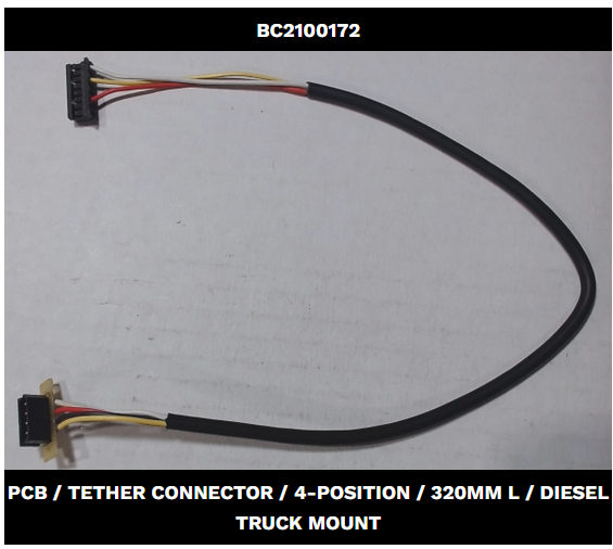
The following is also from MTH & I forgot to post it. Previously I asked if the new harness would add 3 wires for a total of 7 wires. This makes it sound like the replacement harness still has 4 wires just like the original.

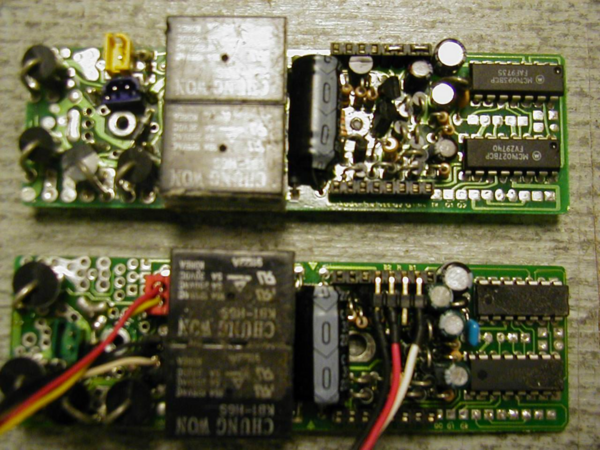
"The harness between A and B units contains only 4 wires. This harness connects the Original ProtoSound board to the DCRU board to make the DCRU operate as a slave to the Original ProtoSound board.

The other wires are found in the powered B unit and come from the pick-up rollers and go to the motors. These are unchanged.

The pictures and instructions show the Slave connections. This is not a detailed instructions on how to slave a powered B unit to a Lead A with Original ProtoSounds. With this information a factory trained ASC tech can create the proper connections between the Original ProtoSound board and the DCRU. There is also a reminder to cut the trace on the DCRU board."

Last edited by Mike C
@Mike C posted:

There are not two slave units. There is only one slave DCRU which is in the powered B-unit & it is not connected to the DCRU in the powered A-unit. People were having problems because the powered B-unit was getting out of sync with the Powered A-unit. IICR MTH charged $35 to do the modification to sync these.

Exactly, my point was and is that slaving the DCRU in the B-Unit to the lead unit will solve the problem of them not being in sync.  I though I made that clear!  Your comments go to illustrate my exact point about sync.

I have to believe that if you had two slaves, they'd have to be daisy-chained in order to stay in sync.  If not, they'd have the same problem as we're discussing in this thread.

Note that I said "IF YOU HAD TWO SLAVES".

I understand. I just wanted to clarify that there should not be two powered A-units involved.

MTH said the harness contains only 4 wires. I recall a comment that once the modification is made that the two powered units are “married” and have to be run together, however I have no way of knowing if that's correct. I suppose you can feed whatever signals you want from the powered A to the powered B. But what comes out the back of the powered B has to operate the dummy A headlamp & coupler.

What is the proper way to sync the powered B to the powered A & yet maintain compatibility to operate the trailing dummy A?

The four wires to the B-unit just keep the DCRU in sync with the A-unit.  I'm pretty sure I never saw an A-B-A all powered with PS/1, so I don't know if one ever existed.  However, given that I'm about 99% sure there's no feedback from the B-unit to the A-unit, I don't see why you couldn't just parallel those four wires from the B-unit to the trailing A-unit and keep them all in sync with the lead engine being the "master".

Thank you to Mike, John and Vern for all your contributions and especially for posting pictures of the boards. I have brought the two engines to my (unfortunately soon to be closing) hobby shop for this project along with the pictures. Their repair guy said he can make the changes with the addition of the tether.

John, I also have the freight version of F3s that do have PS1 and came as a 4 motor set, item 20-2219, and they pulled the whole passenger consist with no problems and at 16 volts and 4+ amps.

@BRicch posted:

John, I also have the freight version of F3s that do have PS1 and came as a 4 motor set, item 20-2219, and they pulled the whole passenger consist with no problems and at 16 volts and 4+ amps.

How much of that 4 amps was the passenger cars?  If these have incandescent lighting, they can easily be using half or more of that power.  I'd be a bit concerned if a plain PS/1 4-motor F3 A-A or A-B-A set was pulling more than four amps without anything else consuming power.

Last edited by gunrunnerjohn

I did note to myself that when those engines are pulling 12 reefers and a caboose, it is only showing 1.5 amps. So you are correct in that the passenger cars lighting is more than half of the total of amps. I’m also looking into options of LEDs for them, but not looking forward to taking those cars apart. Although it will be good to re glue the passengers to their seats. Something that almost all of my KLine passenger cars have….upside down passengers inside.

1.5 amps sounds right for the locomotives, that makes a lot more sense.   Lots of different variations of the K-Line cars, some are easier to upgrade than others.  But if you already have them apart, that's the time to install the LED's.

I have just the LED regulator modules for you if you run conventional...

Passenger Car LED Lighting for Conventional Operators

@BRicch posted:

Thank you to Mike, John and Vern for all your contributions and especially for posting pictures of the boards. I have brought the two engines to my (unfortunately soon to be closing) hobby shop for this project along with the pictures. Their repair guy said he can make the changes with the addition of the tether.

Please let us know how it turns out.

MTH said the new required harness had 4 wires but I don‘t know if that was for the A-unit or the B-unit and they just modified the harness inside the other unit. Or maybe the new harness was supplied with both sections.

You could use the existing harness which has 4 wires. Disconnect the ends inside each unit & splice on additional lengths of wire where needed. But I’m not sure what type of connectors are needed inside each unit.

If the modification uses 3 wires to control the slave unit I‘m still not sure how you would also control the trailing dummy A unit’s headlamp & coupler with only one spare wire. Maybe just don't use one of those functions.

When using the powered B-unit, could its DCRU be controlling the dummy A-unit? I'll open up my B and take a look.

Here's the complete wiring for a master/slave diesel using the PS/1 boards.

Note that the connector added to the boards are wired the same for the master & slave and the cable is a straight-thru 1:1 4 pin cable.  Also in the second shot, note that the white wire starts one position from the end for each board, the red arrows denote an open connection position.

I believe the blue connector on the yellow wire in the slave is for the headlight if memory serves, but it could be for the coupler, I truthfully don't remember.  I see the actual blue connector got left off the graphic, but it's on that yellow wire that goes out of sight.  Obviously, the black lead on the 2-pin blue connector goes to frame ground (wheels).

<----------------------------- Click on images to expand -------------------------------------->

PS1 Master-Slave Wiring N1

<----------------------------- Click on images to expand -------------------------------------->

PS1 Master-Slave Wiring N2

Attachments

Images (2)
  • PS1 Master-Slave Wiring N1
  • PS1 Master-Slave Wiring N2
Last edited by gunrunnerjohn

I opened up all 3 units: powered A, powered B, dummy A & tried to carefully trace where the wires went.

Powered A-Unit:
White wire > connector > Brown wire soldered to bottom of lower board
Black wire > Ground
Red wire > Blue connector on the lower board
Yellow wire > coil coupler switch

Powered B-Unit: The harness goes straight through & bypasses the DCRU. It’s actually made of a front half & a back half and are connected in the fuel tank housing.

Dummy A-Unit: All 4 wires go to what appears to be a small copper fusible links.
White wire > fuse > Blue wire > CV board
Black wire > fuse > Brown wire > CV board
Red wire > fuse > Black wire > coupler
Yellow wire > fuse > Brown wire > coupler

Three wires are needed to sync the B-unit. From bits & pieces I’ve come across it appears the 4th harness wire is used for the rear coupler. Apparently the rear headlamp becomes inoperative.

I saw a comment where a person connected the pickup rollers from the powered A & powered B units & this solved the problem. The power would always be in sync between the units therefore one unit should not drop out & change direction. This may be an easy solution to try.

Mike, per your comment

“I saw a comment where a person connected the pickup rollers from the powered A & powered B units & this solved the problem. The power would always be in sync between the units therefore one unit should not drop out & change direction. This may be an easy solution to try.”

It almost sounds too simple of a solution, but I’m willing to try it. Earlier this week I saw both units going in the same direction back a forth and not even connected to each other. When I put them on my layout they worked fine in the ABBA configuration. But once I coupled them to the passenger set, they fell out of sync again.

@BRicch posted:
It almost sounds too simple of a solution, but I’m willing to try it. Earlier this week I saw both units going in the same direction back a forth and not even connected to each other. When I put them on my layout they worked fine in the ABBA configuration. But once I coupled them to the passenger set, they fell out of sync again.

Well, you're right about one thing.  It certainly isn't as bulletproof a method as locking the two boards together would be.

An ABA with dummy B and A is wired differently.  The 4 pin harness powers a directional HL on the CV board and the coupler.  The PCB is not a fuse, just a PCB with copper traces to solder the harness and output to.

An ABA with powered A units, has the 3 wires to DCRU as John showed to sync voltage and logic to the DCRU from the PS-1 board.  When PS-1 goes forward, logic sent to DCRU to be in forward.  The last wire is coupler which comes from PS-1 via a selection switch.  PS-1 couplers are referenced to ground, so only one signal needed as the other wire is AC ground.

The DCRU provides the directional logic for the Trail A HL on CV board.  This is picked off the relays on the bottom of the DCRU and PS-1 bottom board.  G

GGG, your explanation of how the two setups are wired makes sense. From seeing the earlier posts, would you agree that I still need to add the three wire tether? If so, being an authorized service center, can you help me get the parts needed to accomplish this? I’m having no luck on a local level.

thanks in advance for your reply, Bob.

Add Reply

Post
This forum is sponsored by MTH Electric Trains

OGR Publishing, Inc., 1310 Eastside Centre Ct, Suite 6, Mountain Home, AR 72653
800-980-OGRR (6477)
www.ogaugerr.com

×
×
×
×
Link copied to your clipboard.
×
×