George,

Yes and Yes! The house wasn't painted blue until around 2002. This was after it was sold.  I went by the house not too long after that because I knew the new owner and asked him could I take last visit through. I went to the basement and saw some "graffiti" I put on the wall as a boy. It says "David's Train Club". Not many members but occasionally a friend or two and of course relatives came by for a visit. 

Dave

Last edited by luvindemtrains
@pennsynut posted:

George, I'm up to page 5 so far for a comprehensive review of your progress. I am enjoying the carpentry and extensive planning for your layout. It's really instructive. Awesome benchwork.

I can't take credit for the approach to the bench work.  That's the design of my friend Price, aka The Shadow on this forum.  He's also given me advice on lumber and even helped me build some of it in August 2018.

George

Updated 8/29/2020:

While I am waiting for my track order to arrive from RCS, I am building conduit hangers for installation along the front of the Stone Arch.  First a look at the prototype.  Now, this conduit is newer than what we would expect to find in the 1952 painting "Crossroads of Commerce".  Also, it's on the wrong side of the bridge.  In fact, I have been told this conduit dates from the Conrail years.  In the painting, the line poles and presumably the conduit that carried wires from the line poles ran alongside the left (south) side of the bridge.  Here I am applying a liberal amount of "modeler's license" to borrow the look of the conduit hangers and transfer them to the other side.

DSCN2289 

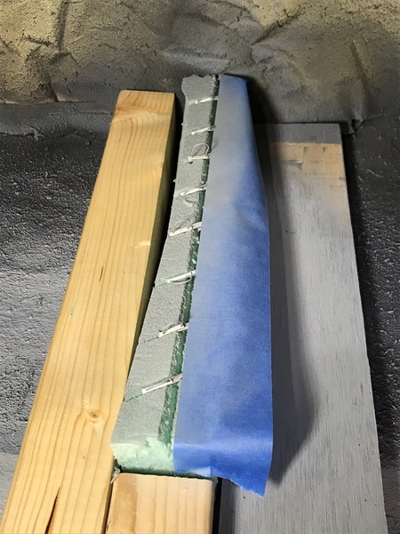
I am trying (poorly, in my estimation) to represent the piece of angle that will hold the conduit.  Here's a photo.  I've used a pin vise to drill holes and install Tichy NBWs (nut, bolt, washer) detail parts.  These have gotten a coat of Testor's Steel paint, which is also acting as the glue.  The protruding NBWs will be sanded smooth to the bottom of the angle iron and a "stirrup" will be glued to it.  The pipe will pass through the loop of the stirrup.  I'm hoping to build 12 of these, if my patience holds out and my lack of fine motor skills permits.    This is a work in progress.

IMG_0236

More when I know it.  

George

Attachments

Images (2)
  • DSCN2289
  • IMG_0236

George,

I like following your thread, and I probably don't do it often enough.  So, I hope this comment isn't too late.  Prototypically, I believe, the PRR would not have used a four-head signal bridge for the functions you desire in the area to be protected.  The West-bound traffic would have been protected by one signal head on the bridge with two sets of dwarf signals at switches #41 and #42 which might be considered a junction or station area.

If I'm correct, this solves the problem of having to modify an MTH signal bridge or kitbash two or more Plasticville signal bridges.  However, it does create the problem of having to locate PRR prototype dwarf signals (I know they are out there, or can be 3D printed), and then figure out how to wire them up to the switches.

No criticism intended, just food for thought.

Chuck

@PRR1950 posted:

George,

I like following your thread, and I probably don't do it often enough.  So, I hope this comment isn't too late.  Prototypically, I believe, the PRR would not have used a four-head signal bridge for the functions you desire in the area to be protected.  The West-bound traffic would have been protected by one signal head on the bridge with two sets of dwarf signals at switches #41 and #42 which might be considered a junction or station area.

If I'm correct, this solves the problem of having to modify an MTH signal bridge or kitbash two or more Plasticville signal bridges.  However, it does create the problem of having to locate PRR prototype dwarf signals (I know they are out there, or can be 3D printed), and then figure out how to wire them up to the switches.

No criticism intended, just food for thought.

Chuck

Chuck,

You are correct.  And I received some excellent advice and help from Bob Bartizek on this subject.  So, I have re-thought the solution and will not use 4 heads on a signal bridge.  The suggestion was made to use a relay tying all 3 sources (2 switches and an occupancy circuit) to 1 signal head on the bridge.  That is the solution of choice at the moment.  I had not thought about the use of dwarf signals, but will consider it.  

Thank you!

George

Updated 9/7/2020:

Worked on the track at the west end of the bridge and got it installed permanently (I hope).  There is a very mild curve there that I tried to make using 3 slightly bent pieces of straight track.  Unfortunately, I wasn't able to do it properly.  It didn't look very good, so I took it up and used a small cut section of O-128 between two sections of straight track.  I ran the Decapod over it at speed (at least as fast as a Decapod might expect to go) as an experiment.  I had to shim sections of adjoining track to get them to the right levels, but it turned out OK.  I also ran the Decapod in reverse over the track section as well.  I think we are good to go! 

Next step is to get the passenger siding down permanently.  After that I will move a bit farther west, installing the Wye (Switch #37.  Then we will turn our attention to the eastern shore, hanging the conduit, cutting and placing the slight curves there, and installing the track feeders.

More when I know it!  

George

Updated 9/9/2020:

Two steps forward, one step back.  Last night I came to some conclusions:

  • The "Spirit of St. Louis" might need an E or F type diesel (A-A set) to pull it.  That would be the correct motive power for the era.  My preference is the tuscan PRR color scheme.  I am casually searching for a set.
  • The engine pocket siding near the Steubenville station is too short to hold the correct A-A set.  Honestly, I'd love to use a set of passenger sharks (BP20) from Weaver, but I don't own one and am unlikely to acquire one.  And they would take a lot of real estate.
  • While actually acquiring a set of E or F units is still up in the air, I am going to plan for the future by reluctantly taking up the length of straight track between Switch #42 and Switch #41.  That means lengthening the straight track east of Switch #42.  It's a PITA but it needs to be done.

Oh, well.  

George

George, You are so right, as much as I love maps, they can be misleading!  It's always best to scope out the place in real life!!

Dave, So you had HO days too!  I recall gumming up the works with glue for ballast, even how hard I tried to keep it out of the workings.  In N scale, I crushed the rail and had a tendency to pull the rail right out of the wee plastic spikes.  None of that won't happen on my O layout!!    O provides a whole new set of problems.  

Updated 9/13/2020:

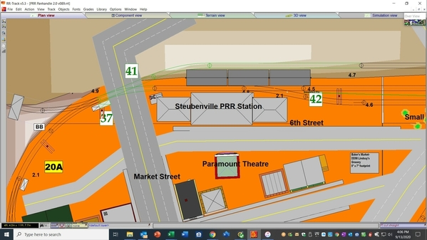
So I'm about to rip up the track I laid last week when a thought occurred to me.  Just how big will the Steubenville Station be?  Will it fit in the allocated space?  What will it look like?  So I went to the trouble of playing around with Visio and generating what I thought would be a realistically proportional foot print.  The real station was enormous.  I don't have plans and dimensions, but it was huge.

43161245_10156074966434071_6411452829289938944_o

So I create the footprint and cut it out.  It's 9.5" x 4.5".  Uh, really?    To represent the above?  

I don't think so.  I re-examined the area and made a few executive decisions.

  • Baker's Market, which in the real world was on the west side of 6th Street, is moving to the other side of the street.
  • The space it occupied will be used to give the station a larger, more prototypical look.
  • All of 6th Street will be moved downward to create more space for the station.
  • The station will end up around 30-32" long.  Much better!

Here's the new area:

20200913 PRR Station Area

More when I know it.  

George

Attachments

Images (2)
  • 43161245_10156074966434071_6411452829289938944_o
  • 20200913 PRR Station Area

Updated 9/17/2020:

Today I began re-organizing the area around the Steubenville PRR station.

  • Created a footprint (white paper) for the new station (30-32" long x 9" wide)
  • Created a footprint (white paper) for Baker's Market (5"x7"), now restored to the west side of 6th street
  • Positioned the station and store further east (below the tracks).
  • Laid out the approximate positions of these items and the tracks on the layout itself

IMG_0261

More when I know it.  

George

Attachments

Images (1)
  • IMG_0261

Updated 9/24/2020:

A fair number of things have been started in motion since I last posted:

  • The PRR Station at Steubenville has again been re-sized, this time to account for its total footprint from track to Sixth Street. It's now ~36"x10".
  • Additional research materials on the station have been acquired.
  • An order for flemish bond brick sheets for the station walls has been placed with The N Scale Architect.
  • JTT red clay tile sheets (for the station roof) have been ordered.
  • A number of downspouts and other details have been ordered from Crow River Products.
  • A case (50 pieces) of GarGraves WT101-37 rigid phantom 37" straight track has been ordered.


Things are moving!

More when I know it.  

George

Last edited by G3750

Updated 9/26:

While I wait on the rigid GarGraves to arrive (it's immediate use will be on the eastern approaches to the bridge), I am focused on buildings and scenery in the Steubenville station area.  Right now, there are several projects underway:

  1. I am working on accurately determining the outside dimensions (including the indentations and ornate pilasters) of the Steubenville PRR station using photographs.  Once those are right, I will transfer them to a Visio floor plan of the model.  Material selection comes after that.
  2. My cut stone arch bridge from Crow River arrived.  I washed it to remove any mold release agent.  I need to determine its final width and then paint and assemble it.  It will be mated with some stone retaining walls near the end of the passenger siding.  Precise final positioning is still to be determined (TBD).
  3. The Steubenville hillside directly beyond the passenger siding is still in the concept phase.  That's vague but I expect it to solidify soon.  Hand in hand with that is the area in the corner which will house the (fake) Gould No. 5 tunnel (inaccurately and conveniently moved very near to the station ).  There's a lot of scenery work left in this step.

Once all that is done, benchwork construction south of the station can commence. I really don't want to build scenery by popping up out of an access hatch. Might as well do it while the area is open.

George

Last edited by G3750

Updated 10/2/2020:

Unfortunately, most of this week has been spent on trivia (finalizing the contents of 2 mid-term exams, uploading 22 video lectures, taking my wife to her appointments, etc.) instead of model railroading.   

However, some slight amount of progress happened despite the universe's headlong rush towards entropy. 

  • Track and roofing material have been ordered, as previously discussed.
  • I have identified the types of HO houses that I want behind the Steubenville station. They are:
    • Walthers Two Story Frame House (933-3786)
    • Walthers Tillman Farm House (933-3789)
    • Branchline Trains Albion Catalog House (181-621)- quantity 3
  • I mocked-up the footprint and approximate locations of the houses.  Shoot, they even fit the allotted space!  

More when I know it.  

George

George, I am with you on doing other things besides the layout!  I'm sure your wife wouldn't call her appointments "trivia"!    I had to take Kim to get trigger finger surgery on her thumb Monday.  Due to reschedules, it was completely locked up!  Now it is fine other than a sore incision.

  • I mocked-up the footprint and approximate locations of the houses.  Shoot, they even fit the allotted space!    How in the world did that happen??  

Updated 10/3/2020:

Sometimes things just "click".  While waiting on various items to arrive, I decided to search for the HO houses that will go above the Steubenville station.  The Walthers website is a great source;  they seem to have the largest number of HO structures on the planet.   I identified Dave's (luvindemtrains) grandmother's house and have acquired that kit.  I also have one of the houses to its right (Tillman Farm House).  I was intrigued by the 3 identical houses at the right of the photo. 

Hillside Above Station 001

They looked vaguely familiar to me.  They are Albion Catalog Houses.  Yes, you buy them from (get this) Sears!  They come unassembled on a truck.  Unload the truck and assemble!  (Note to Moderator:  This is a very old (1920's) advertisement; copyright (if there ever was one) has to have expired).

70-the-albion

Here's the kicker.  The reason the house looks familiar is that my maternal grandparents lived in one!  My father told me that his father-in-law built his own house in the 1920's.  I never explored the subject, but I remember the floorplan and outside appearance of the house.  It seems to have been an Albion home with some modifications (expansions).  And being a carpenter, cabinet maker, and ship builder (remember the model ships he created?), this makes a lot of sense.

Thank you, Dave!  Your interest in this scene sparked my curiosity and helped me learn something!

George


Attachments

Images (2)
  • 70-the-albion
  • Hillside Above Station 001

Yeah, there's a subset of folks out there that look for Sears houses and other kit homes that were offered during the interwar period. Montgomery Wards sold a line too, I think called Wardway Homes. Another outfit was Bennett. Quite a few of the "Craftsman" style homes, some call them four-square homes for their symmetry, like the one your grandparents had, were kit homes. Kinda amazing that there was a time that you could order a house from the Sears or Wards catalog.

Anyway, the Walthers kits look sharp...I'll be interested to see how it works out in your application.

Last edited by pd

Updated 10/9/2020:

Despite life's best attempt to derail me with trivia , some progress has been made.

  • A friend (who I will give a shout-out to when all is done) provided a circuit design and test circuit for taking 3 inputs to a signal head.  Below are 2 still photos on my testbed showing the position of a DZ-2500 switch machine controlling the aspect of an MTH signal.

BB-Test 001

BB-Test 002

  • I am planning to install that signal bridge soon and decided to pull the wire for the Western Switch Bus.  That's three 100' lengths of 16 gauge wire.  RED for AC hot; BLACK for Ground; WHITE for the Data Wire Driver (TMCC control of DZ-2500 switch machines).  Here's what 300' of pulled wire looks like.Pulling Switch Bus 1 [Western)
  • I have found a source for 4 of the HO Albion Catalog Houses at a decent price and placed an order.  They are on back-order and I expect them in 3-4 weeks.  I got to use my NMRA discount, making the deal even sweeter!

More when I know it. 

George

Attachments

Images (3)
  • BB-Test 001
  • BB-Test 002
  • Pulling Switch Bus 1 (Western)

Sounds like progress to me. That's pretty cool to have a legit working signal. I never got that far on my last layout but it's on the wishlist this time around.

I have a question about your backdrop. I have decided NOT to build a coke plant. I want to represent one with a backdrop. Did you have to provide the photo for the back drop? Or did they have stock stuff on hand?

Add Reply

Post

OGR Publishing, Inc., 1310 Eastside Centre Ct, Suite 6, Mountain Home, AR 72653
800-980-OGRR (6477)
www.ogaugerr.com

×
×
×
×
Link copied to your clipboard.
×
×