I have an FA-2 ABA set. The Powered A unit is Proto-Sound 3 and the unpowered B and unpowered A units are from an older Proto-Sound 1 set. They are all the same liveries so they look like they belong together on the outside, but the components are obviously not 100% compatible on the inside.

Typically, there is an operating coupler on either end of both A units and the dummy A unit has a tether that connects back through the B unit to the powered A. Because the powered A is ~12 years newer than the dummy units, the connectors are not compatible, so the rear coupler will not function. Strangely enough though, the front coupler wont function either even though it is attached directly to the powered engine.

So my questions:

1. Is the front coupler not working because there is no connection to the rear coupler? Or is there another problem altogether? I bought the engine used but it functions perfectly other than the coupler problem.

2. Is there some way I can get the rear coupler to work as well? I figure it would involve wiring the 2 coupler leads that head to the rear tether up to the dummy A unit, but what is the best way to go about this?

Any insight would be appreciated.

Original Post

Replies sorted oldest to newest

The front coupler malfunction has nothing to do with the tether going to the rear engine, there's no connection between the two.

The PS/1 couplers are not compatible with the PS/2 or PS/3 couplers.  First step will be to obtain and install a proper coupler on the rear unit.

Good to know. The effort / price involved in trying to acquire and replace the rear coupler with a PS-3 compatible coupler is probably not worth it. Especially considering shipping & import prices to Canada (Unless I happen to find spare parts at a train show once Covid is done).

As for the front coupler, any idea what the malfunction could be? Loose wire? I always thought the couplers were a fairly fool-proof element of the engine, with not much that can go wrong with them.

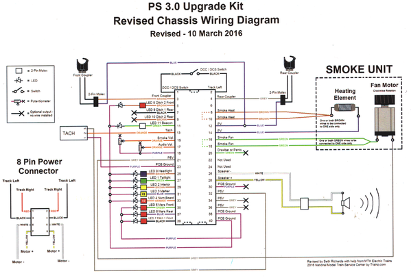
As a final check, you can use a meter to check end to end from the 40 pin connector on the PS/3 board through the coupler.  If it measures end to end the coupler resistance and nothing is grounded, it's most likely the board is bad.  The front coupler goes from pin-3 to PV on pin-12, the rear coupler goes from pin-4 to PV on pin-12.

Click in image to expand graphic

PS 3.0 Diesel Upgrade Kit Wiring Diagram

Attachments

Images (1)
  • PS 3.0 Diesel Upgrade Kit Wiring Diagram

Huh, John you are wrong.  For PS-3 Diesels the front coupler will not work with out a rear coupler sensed or a jumper with a resistor in place.  F units should come with that jumper. 

So you can get a ps-2/3 type coupler and replace the Trail A PS-1 coupler with the PS-2 type and then both will function when you wire it up to the Rear coupler connection on the PS-3 engine.  G

The PS3 diesel boards need a load on both couplers to prevent the FET on the board from failing.  If only one coupler is connected, it may work for a while, until the FET fails.  That is why newer F units that have protocouplers on both ends  include a resistor load for when a dummy coupler is substituted for close coupling.  This is not a problem with the stacker boards.

Last edited by Jon G
@GGG posted:

Don't believe me huh:-).   Tech bulletin 07-27-16A

Oh, I believe you, and you got back up from Jon, can't ignore both of you!   Besides, now that I cruise through the service notes, I find Jason even provided a diagram.   For some reason, I missed this when it came out, and the issue never actually bit me.  I do note indeed this issue surfaced years after I attended the training classes.

I'm still at a loss as to why the couplers are interlinked, that's very odd.  I have to believe that was some design screw-up, I can't imagine it was intended that way from the beginning.  However, now I know, and I'll strive to remember in the future.

Attachments

Images (1)
  • mceclip0

Hadn't checked the forums for a few days, interesting to see there was further development on this topic.

So in the short term, how would I go about making myself one of those resistors to "fool" the engine into thinking a rear coupler is plugged in? Also, where does this resistor go? Does it just plug into the tether port at the back of the engine?

Add Reply

Post
This forum is sponsored by MTH Electric Trains

OGR Publishing, Inc., 1310 Eastside Centre Ct, Suite 6, Mountain Home, AR 72653
800-980-OGRR (6477)
www.ogaugerr.com

×
×
×
×
Link copied to your clipboard.
×
×