PROBLEM SOLVED. SEE POST BELOW, Dated September  2, 2022

I have a Kohs GG1 that has been retrofitted with PS3 extracted from a Railking GG1.  Rail King part number is 30-5118-1.  The GG1 has two 9000 series Pitmann Motors

After about 3-4 minutes of running, on the rails, the GG1 stops abruptly (no gentle slow down).  Within a second or two it restarts.  The restart is just as abrupt, and the loco resumes at the original speed setting.  It then repeats this behavior.  During these halts, I can control the horn and the headlight stays lit.  It is as if power from the motor board (if there is such a thing) is momentarily cut and then restored, while everything else is uninterrupted

This is a new phenomena.  The PS 3 was installed in the fall of 2019

My three questions are,

1) Based on my tests below is my analysis correct that the motor driver board cutting in and out is the cause of this?  Or can it be something else?

2)  The current through the DCS motor driver board when the loco is moving is 1.40 A.   I assume this is within the capabilities of the PS 3 board?

3)  Can this be repaired?

Any help will be appreciated

*******************************************************

Here are the tests I performed

ROLLER TEST:  I placed locomotive on test rollers.  2 rollers per truck (total of four), but only one roller is powered through the DCS. There is a test light across the wheel pickups, just before going into the DCS board. But there are a few inches of wire between the pickoff point and the board connector.  Current is measured with a high quality Fluke multi meter in the input to the TIU (variable channel #3). Both 4 wheel trucks have been removed

0.450 A: Current measured without loco on the track

0.606 A: Current with loco on track (after about 1 min…initial current is 0.8 A)

0.634 A: Locomotive started up

1.26 - 1.32 A:  Start test, locomotive at 35 SMPH

1.20 – 1.27 A:  End test after 10 minutes.  Ran continuously and smoothly without problem.  This means the motor driver board can continuously drive 1.27 minus 0.63 = 0.64 Amps


TRACK TEST:

Added a headlight (LED)

0.450 A: Current measured without loco on the track

.610 A: Track power on

.619 A: Locomotive started up.  (A bit higher than in roller test)

1.7 to 2.0 A:  Locomotive running on track, running at 35 SMPH. This means the driver board must be putting out 2 minus 0.62 = 1.4 Amps

After about three minutes, the locomotive started the abrupt momentary halting routine.  During these halts

1) Pick up lamp stays lit—indicating the board is getting power

2) Current drops to .620 A, indicating motors are not getting power

3) Headlight stays lit and I can activate the horn, indicating board is still “active”  (The fact that it abruptly resumes its original speed suggests the same thing)

When motors start turning again, the GG1 rapidly returns to the pre-halt SMPH

Running at 25 SMPH, decreases current to 1.5 A.  But I get same halt/restart behavior after 5 minutes

Last edited by John Sethian
Original Post

Replies sorted oldest to newest

I’ve never been inside a Koh’s & Company anything, …..too rich for my blood, ….but nonetheless, how is this engine powered by Kohs?…..I see in your write up that this engine was converted in 2019, but that don’t really mean a hill of beans if it’s been a ticking time bomb waiting for 2022 to go off……I’d check mechanicals first, then disconnect the motor(s) from the board set and test them individually. Find out the max amp draw testing the motors on a straight power source,…..somebody might be able to note on here the max draw that board set can handle before it goes wonky……if your locomotive creeps up on or exceeds the allowable amperage being run on straight power, , then it’s game, set, match, time for plan B ……

Pat

Pat

Thanks for your input!  And I am glad you recalled my article!

The "roller test" I did (as cited in my original post) tells me there is nothing funky with the motors, the wiring, or the mechanicals.  I should have also mentionned in my original post that nothing felt warm during the roller test.

But your comment about "somebody might be able to note on here the max draw that board set can handle before it goes wonky" is why I asked the question if the PS 3 board can handle a motor drive of 1.4 Amps. If I am indeed exceeding the limits of the board, than that's the time bomb you have referred to. But if the board capability is more than that, then it would suggest something else is going on

Last edited by John Sethian

Pat

Thanks for your input!  And I am glad you recalled my article!

The "roller test" I did (as cited in my original post) tells me there is nothing funky with the motors, the wiring, or the mechanicals.  I should have also mentionned in my original post that nothing felt warm during the roller test.

But your comment about "somebody might be able to note on here the max draw that board set can handle before it goes wonky" is why I asked the question if the PS 3 board can handle a motor drive of 1.4 Amps. If I am indeed exceeding the limits of the board, than that's the time bomb you have referred to. But if the board capability is more than that, then it would suggest something else is going on

How is that chassis powered/driven?…..what motor(s)?….what’s the drivetrain makeup?

Pat

@harmonyards posted:

How is that chassis powered/driven?…..what motor(s)?….what’s the drivetrain makeup?

Pat

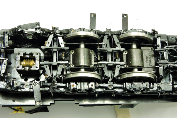
Chassis powered by two Pitmann Series 9000 motors one at each end.  Each motor drives a gearbox that powers three axles through worm gears.   There are ball bearings everywhere. The photos below show the arrangement

4620

4621

4538

4611

Here are the specs on the motors, third column over for 12 volt

5459

Since I was not running anywhere near maxium torque in any of my tests, the current I measured for two motors is consistent with the above

I just ran a similar running test with an MTH FM Train Master with PS 3.  Using the same protocols, the motor current draw was only .80 Amps. So I may indeed be up against a PS 3 current limit. But I'd like confirmation of that before changing to more efficient motors.

Thanks again

Attachments

Images (6)
  • 4522
  • 4620
  • 4621
  • 4538
  • 4611
  • 5459
Last edited by John Sethian

Ain’t gonna be the motors that are the problem, ….doubt you’ll get any more efficient than the Pittmans it came with……what I see is just ALOT happening under the hood of that GG1!…..don’t get me wrong, it’s a work of art,…even though they’re smaller Pittmans, I’d be willing to bet the 2 are kinda amp hungry given all the machinery that shaft has to go through to transmit power to the wheel sets…..correct me if I’m wrong, but all PS2 or 3 diesels and or electrics that are double motored, are powered by two small Mubachis …..not two honking Pittmans driven through an entire planetary gear arrangement…..😁

Pat

“Since I was not running anywhere near maxium torque in any of my tests, the current I measured for two motors is consistent with the above”

the motors aren’t running out of their intended specs, but I do believe the board set can’t deliver what the motors want via what the tach sensor is telling the board set to do …..the tach sensor doesn’t care if the board set eats itself alive trying to feed two grown adults vs. two small children…..all it knows is more, more, more….meanwhile, the board set is just like Scotty on Star Trek, …..” I’ve given er all she’s got Captain!” …”She’s gonna shake herself to pieces!” ….

Pat

You could very well be correct about the planetary gear arrangement, so I need to look into that.  Incidentally, these are not the motors it came with...those were even longer 9000 series motors.    I also think they are overkill for this (to give Kohs bragging rights, no doubt).   I am sure there are mor efficient motors out there

And you are correct about the MTH set ups.

Again though, I'd like to know the current spec on that PS3 motor drive. Anyone else know?  My tests show 0.64 Amps should be good.

And for that matter, I'd like to know what is actually happening!

Last edited by John Sethian

You could very well be correct about the planetary gear arrangement, so I need to look into that.  Incidentally, these are not the motors it came with...those were even longer 9000 series motors.    I also think they are overkill for this (to give Kohs bragging rights, no doubt).   I am sure there are mor efficient motors out there

And you are correct about the MTH set ups.

Again though, I'd like to know the current spec on that PS3 motor drive. Anyone else know?  My tests show 0.64 Amps should be good.

How exactly are you concluding actual motor consumption being delivered via the driver portion of the board set?……and can you conclude consumption (amps) when the locomotive is on your layout at the point of failure?……you’d have to correct me if I’m wrong, but if you’re pulling your amp readings from the AC output, ie; reading it from the rails, that’s a different deal than what’s happening between the driver and the DC motors….in other words, the board set might be consuming what’s considered tolerable, but what’s happening between the driver and the motors might not be,……

Pat

@harmonyards posted:

How exactly are you concluding actual motor consumption being delivered via the driver portion of the board set?……and can you conclude consumption (amps) when the locomotive is on your layout at the point of failure?……you’d have to correct me if I’m wrong, but if you’re pulling your amp readings from the AC output, ie; reading it from the rails, that’s a different deal than what’s happening between the driver and the DC motors….in other words, the board set might be consuming what’s considered tolerable, but what’s happening between the driver and the motors might not be,……

Pat

Measuring the current input into the TIU with the motors running and not running, then subtracting the difference.  Unless there are current  multipliers or transformers in the PS 3 board, the RMS current should be continuous. As a check,  the current I got with the roller test where the meter was in one of the leads to the rollers, matched the current input to the TIU.

Last edited by John Sethian

Assuming current is continuous.  Are there current  multipliers or transformers in the PS 3 board?   The current I got with the roller test where the meter was in one of the leads to the rollers, mactched the current input to the TIU.

Wellllllllllllll,……it’s not 100% conclusive of what’s actually happening between the driver and the motors, …yes, it’s continuous, but reading the amps on the outside doesn’t really tell us what’s happening on the inside ….( per say )  …..we know the motors are hungry, ….they have to be with all that motion happening….and we know you’re going into fault. So rather than trying to figure out a mathematical ah-ha ….can you perform a couple tests?…is there any way to uncouple one motor, and make that truck in sense a dummy with out having a baby??…or is that gear train just so complex you’d need a degree in Astro Physics to pull it off?….also, I see what looks like two huge weights??…are they super heavy?…does that engine weigh as much as a real GG1 ( I mean we are talking Kohs here) so can we take things away and perform another running test to determine if we’re on the right path??…..it might be too late for the board set, but nothing beats a try but a fail,….If you can run on one motor, and it’s successful, maybe an option ( If space is available) is to add a second board and treat the one engine like a lash up, or maybe John or George could suggest some sort of slave option??…I don’t know 100% but my mind says those two motors just have alot to do and the board set finally said enough is enough…..😉

Pat

WOW!  I never saw that kind of complexity, that sucker should be a real stump puller!  The PS/3 board should be able to deliver more than 1.4 amps, but then we don't know what's happening with it's on the rails and running.  Pat is right, the MTH GG1 has two 3xx series Mabuchi motors, and they don't have that tortuous path to get to the wheels!

Thanks John! That current limit is exactly what I need! 

I am not sure this is as tortuous a path as you two think it is. I am not sure there are planetry gears in that tower.  The overall ratio between motor and drive  shaft is 0.875:1.  So I think there are probably just spur gears.  In which case it's a common O scale drive system to have a tower drive from motor shaft to drive shaft, and then a worm gear boxes to transmit the power to each axle.   Think Sunset with spur gears replacing the belt drive.

I have other more efficient motors on hand, which can provide the same torque at 2/3 the current. But if John's limit (and my mesaurement technique)  is correct, I should not be having problems with what I have  So, I can measure the current directly to one of the motors with the roller test. That should answer Pat's concerns. I will report back. Probably won't happen until tomorrow.

Last edited by John Sethian

You could very well be correct about the planetary gear arrangement, so I need to look into that.  Incidentally, these are not the motors it came with...those were even longer 9000 series motors.    I also think they are overkill for this (to give Kohs bragging rights, no doubt).   I am sure there are mor efficient motors out there

And you are correct about the MTH set ups.

Again though, I'd like to know the current spec on that PS3 motor drive. Anyone else know?  My tests show 0.64 Amps should be good.

And for that matter, I'd like to know what is actually happening!

How did they fit longer 9000’s in there?…..the stubby motors already look like they’re at the space limits now, ……what’s the full Pittman model number of the OE motors?…do you have that handy?….and why go to the stubby motors in the first place?…what was the criteria for going backwards in motor size?….

Pat

I'm only adding one cent here and I only glanced over your issue.

Obviously there are factors that change what the board can do. If you ran at lower track voltage for example, or if something isn't providing full power to the board, I'd guess that would seem like the board would handle less.

I believe these PS3 boards handle good loads. I have them in other brand one gauge engines that are power hogs without issue.

I had a one gauge engine that had a power path burn out. It was a printed circuit board that carried power from wheel pickups and the actual printed path was burned so that was one less point of power. That engine did not run right until I fixed it.

Of course none of this may apply, I'm only throwing something at you to consider looking at everything.

I've seen MTH board equipped engines stall because the tach didn't get the expected response from the motors. I've had chaffed wires rubbing the frames. Even a missing insulator inside a truck power point causing havoc. An old PS1 Allegheny I upgraded, had an intermittent short from a protrusion touching a smoke unit power pad. Took me near a year to finally find that one. It only occurred on certain turns or shell twists.


I will watch this thread and try to stay out of the way. Good luck and I will try and help with the little I can add.

Last edited by Engineer-Joe

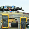
In response to Pat’s concern that I may not be measuring the motor current properly, I added a current meter to the leads to one of the motors:

5460

The meter on the right (set at AC) measures the current to the TIU, the meter on the left (set at DC) measures the current to the front motor. To keep things unambiguous, the rear motor is out of the circuit.  The meter on the right stabilizes at 0.620 Amps

Note this is a roller test

This is what I got

SMPH   One Motor         TIU          TIU (adjusted)

0            0                    .620                    0       

15          0.57             .844                  ,224

20          0.60             .902                  .280

25          0.64             .954                  .334

30         0.68             .975                  .350

35          0.70             1.02                  .400

It appears that measuring the current through the TIU is not an accurate way to measure the current through the motor (Thanks Pat) AND at 35 SMPH on rollers I am right at the limit that GRG cited (0.70 x 2 = 1.4 A), so that explains why I had the drop outs when running on the layout.

As I said in a previous post, I have other motors I can try.

Attachments

Images (1)
  • 5460
Last edited by John Sethian
@harmonyards posted:

How did they fit longer 9000’s in there?…..the stubby motors already look like they’re at the space limits now, ……what’s the full Pittman model number of the OE motors?…do you have that handy?….and why go to the stubby motors in the first place?…what was the criteria for going backwards in motor size?….

Pat

Yes.  In order to fit the longer OEM 9434 motors, Kohs had to resort to a "Unique soft universal joint"  which was two discs which engaged each other via nylon pegs. A conventional U joint would not have fit

4513

As you can see above, these pegs break easily.  (Which by the way, is how I got this thing so inexpensively).  Going to a 9232 Pittman allowed me to use a more conventional universal joint:

4610

Attachments

Images (2)
  • 4513
  • 4610

Given the fact that the motors are driven using PWM, you may not be getting an accurate reading as well.

It’d be nice to know the amp draw of the two combined motors without the PS3 board set in play,  …..maybe via a simple rectifier set up, or straight DC track power, and then determine consumption requirements under load on his layout, ….no??

Pat

@harmonyards posted:

It’d be nice to know the amp draw of the two combined motors without the PS3 board set in play,  …..maybe via a simple rectifier set up, or straight DC track power, and then determine consumption requirements under load on his layout, ….no??

Pat

That would be a good approach, set the DC meter on the chassis and run it around and see what the current draw is.  Probably even easier to use DC on the tracks and just measure the current.

Last edited by gunrunnerjohn

Given the fact that the motors are driven using PWM, you may not be getting an accurate reading as well.

That's why I originally measured just the AC input. I know what the Fluke's algorithms are for a simple 60 Hz sinusoidal waveform.   I don't know how it interprets a pulse width modulation waveform

As for rewiring to work on straight DC and measure that current..  I am not up for doing a science experiment here, and I am not sure it will give useful information anyway. Other motors have a higher Nm/A  (torque per amp), so that seems to me to be the most expedient approach.

Besides John, I remind you of your tagline

In response to Pat’s concern that I may not be measuring the motor current properly, I added a current meter to the leads to one of the motors:

5460

The meter on the right (set at AC) measures the current to the TIU, the meter on the left (set at DC) measures the current to the front motor. To keep things unambiguous, the rear motor is out of the circuit.  The meter on the right stabilizes at 0.620 Amps

Note this is a roller test

This is what I got

SMPH   One Motor         TIU          TIU (adjusted)

0            0                    .620                    0      

15          0.57             .844                  ,224

20          0.60             .902                  .280

25          0.64             .954                  .334

30         0.68             .975                  .350

35          0.70             1.02                  .400

It appears that measuring the current through the TIU is not an accurate way to measure the current through the motor (Thanks Pat) AND at 35 SMPH on rollers I am right at the limit that GRG cited (0.70 x 2 = 1.4 A), so that explains why I had the drop outs when running on the layout.

As I said in a previous post, I have other motors I can try.

I wasn’t trying to be condescending, let me be clear on that, ….John put it in better terms than I did….beings it’s PWM driven, the meter readings ain’t exactly true …is there anyway you can simply disconnect the entire PS3 board set and rev this guy up on a rectifier, or straight DC power?….with both motors parallel?…thats will tell the true story of the amp consumption by both motors,….beings the board set is constantly adding or subtracting voltage ( in an attempt to cruise ) your Fluke can’t take this into account, …Id think your meter is seeing some float, because by your numbers, everything seems honky dory …..I’ve built a lot of large heavy articulated steamers with gigantic Pittmans, and believe me, id be ok with 1.4 amps raw ( that’s pulling a train BTW) ……most big straight frame engines ( 4-8-2s, 4-8-4’s etc, etc,.) with large 9400’s singles I try to get well below an amp before sending them down the road to have electronics added, ….but I do my testing long before the package is added, …..I use my Z4000’s amp meter as a start, but I back it up with my Fluke, cause Z4000’s can be known pathological liars…I can’t say for sure, but my gut is telling me your Kohs with two Pittmans and a dizzying array of drive train might be tugging closer to 2 amps, or even above ….and that might be too much for the PS3 to handle under load…..

Pat

That's why I originally measured just the AC input. I know what the Fluke's algorithms are for a simple 60 Hz sinusoidal waveform.   I don't know how it interprets a pulse width modulation waveform

As for rewiring to work on straight DC and measure that current..  I am not up for doing a science experiment here, and I am not sure it will give useful information anyway. Other motors have a higher Nm/A  (torque per amp), so that seems to me to be the most expedient approach.

Besides John, I remind you of your tagline

A rectifier is 4 wires …6 in your case,….swapping motors is gut the tool box time ….I’d opt for the easier approach…..this will tell the story for sure…..tossing motors at it in hopes of a solution seems like dart board diagnostics…….especially given the testing you’ve already gone through…..

Pat

1.1 to 1.4 A on straight DC

Voltage 10.4 Volts

Power: MRC Pure Power DC

Pickup wires go directly to the motors

PS3 board completely disconnected

Current and voltage measured with Fluke digital Multimeters at the power supply

Loco orbiting the track, no train per previous tests

           25 laps

           10 minutes continuous, no incidents

           Estimate 70 SMPH based on lap times

           This is twice as fast as previous tests in which halts were observed after 3 minutes

           Its also much faster than I would run a train

Conclusion?  (I have my own thoughts, but I shall await input from others)

Last edited by John Sethian

1.1 to 1.4 A on straight DC

Voltage 10.4 Volts

Power: MRC Pure Power DC

Pickup wires go directly to the motors

PS3 board completely disconnected

Current and voltage measured with Fluke digital Multimeters at the power supply

Loco orbiting the track, no train per previous tests

           25 laps

           10 minutes continuous, no incidents

           Estimate 70 SMPH based on lap times

           This is twice as fast as previous tests in which halts were observed after 3 minutes

           Its also much faster than I would run a train

Conclusion?  (I have my own thoughts, but I shall await input from others)

Well now you know what the real draw is, ….1.1-1.4 shouldn’t have killed the PS3 board,…those are numbers I ship off custom builds to have electronics added with no fears,…..so you’re not seeing any spikes, any lurching, motors are fairly cool to the touch after 25 laps?…I have no clue how big your layout is, but I go by time, not laps made….I see you went 10 minutes, so if there was something going askew, I’d expect to see it happen within that time frame…..SO before you go bananas ripping out motors, reach out to GGG ( George ) …..his email is in his profile, ….George can do component level repair to those boards when it’s possible…..I don’t know if John does or not, so I’ll let him defer it back to George, or himself if he wants….I’d let George take a look at the board, and see if he can breathe life back into it….those amp draws on that engine with two Pittmans, going through all that rotating mass is way better than I would think……..I surely wouldn’t be doing motor swaps at those numbers…..I doubt you can clean it up much better than that,…..BUT since you’ve got it running on DC, pull your train and THEN let’s see your numbers…….the numbers I quoted you on my builds, are same as yours, but pulling 35 scale freight cars for hours…..😉

Pat

@harmonyards posted:

Well now you know what the real draw is, ….1.1-1.4 shouldn’t have killed the PS3 board,…

GOOD TO HEAR!

those are numbers I ship off custom builds to have electronics added with no fears,…..so you’re not seeing any spikes, any lurching, motors are fairly cool to the touch after 25 laps?…

NOTHING.   VERY SMOOTH RUNNING,  MOTORS COOL

I have no clue how big your layout is,

115 feet per lap

but I go by time, not laps made….I see you went 10 minutes, so if there was something going askew, I’d expect to see it happen within that time frame…

TWICE THE SPEED, FOUR TO FIVE TIMES THE DURATION THAN WHEN FAILURE MODES OCCURRED BEFORE

..SO before you go bananas ripping out motors, reach out to GGG ( George ) …..his email is in his profile, ….George can do component level repair to those boards when it’s possible…

YOU WILL RECALL MY ORIGINAL POST WHERE I ASKED IF COMPONENTS CAN BE REPLACED/REPAIRED.

..I don’t know if John does or not, so I’ll let him defer it back to George, or himself if he wants…

I'LL WAIT FOR JOHN TO REPLY BEFORE REACHING OUT TO GEORGE

.I’d let George take a look at the board, and see if he can breathe life back into it….those amp draws on that engine with two Pittmans, going through all that rotating mass is way better than I would think…

AS IS SAID ABOVE, THAT IS A PRETTY COMMON DRIVE TRAIN FOR 2 RAIL O SCALE.  THAT IS HOW THEY GET SUCH SMOOTH RUNNING LOCOMOTIVES.  A LOT OF THEM HAVE HO SCALE DCC DECODERS IN THEM, SO CURRENT DRAW HAS GOT TO BE SUB 1.5 AMPS

…..I surely wouldn’t be doing motor swaps at those numbers….

I WILL WAIT TO SEE WHAT JOHN/GEORGE SAY FIRST.

.I doubt you can clean it up much better than that,…..BUT since you’ve got it running on DC, pull your train and THEN let’s see your numbers……

I KNEW YOU WOULD ASK THAT!  THE ONLY THING I COULD EASILY ADD ARE PASSENGER CARS, BUT I DIDN'T WANT TO COMPLICATE THE MEASUREMENTS WITH LIT CARS  (YES, I KNOW HOW TO SUBTRACT, BUT ....)  WHAT I DID WAS SUCH AN OVER TEST IN SPEED AND TIME COMPARED TO WHEN THE FAULT WAS OBSERVED, THAT I DON"T THERE IS A PROBLEM WITH THE MOTORS OR DRIVE.   

.the numbers I quoted you on my builds, are same as yours, but pulling 35 scale freight cars for hours…..😉

UNDERSTOOD

Pat

THANKS AGAIN!

JOHN

MTH one scale that use larger motor have the rectifier heat sunk.  In addition, when they used PS-32 board they added brass heat sink to the motor fets.  PS-3 boards do a have a temp thermistor sensor that will kill power if temp gets too high and it is possible the Flash code may have a temp setting.

A lot of info to read above.  Are you saying this worked fine since 2019 and just started to act up?  If the engine stop but lights and sounds remain on, and you have control which I think you said you do, then the board still has power and I believe the motor fets are overheating, or some component related to motor operating.  That is shutting down the motor and you get the abrupt stop.  G 

Maybe George can take a look at your board, and build it with a little overkill, …add the one scale heat sinks??..and set up a better flash code??…as I recall you did harvest this set up from a Railking engine, so it’s possible what George says rings true ……all the way back to the beginning when we mentioned this might’ve been a ticking time bomb, ….waiting for 2022 to go off!….😁

Pat

Nothing is so easy as the job you imagine someone else doing!  Thanks Pat. I can't "harden" the board and the problem is if this worked for a few years, then something happened to the board.  I can test board but chances it will run fine on a test unit which only uses a single HO motor.

I would transplant the board into a MTH PS-3 engine and see how it behaves.  If it runs fine the issue is those 2 big motors.  If it behaves poorly even in a MTH engine, the board did get damaged.  You could solder a test bulb to the DC output of the rectifier.  This is primary PV for the Motors.  Run it.  When it stops see if the bulb goes out.  If it does that mean the Rectifier stopped rectifying.  But more likely is heat generation around the motor fets.  The current draw does not seem excessive, but they put a thermistor in there for a reason, so I assume there is some limitation.  Additionally, only one of the motor fets drive the motor, the other is in there for some fully unexplained reason (when I asked years ago).  Something about controlling heat in the motor drive circuit.

I am out of diesel boards and used up my G scale PS-32 boards.  Which would not be a good fit anyway since they drive bulbs not LEDs and the whole upgrade would need to be modified.  G

@GGG posted:

Nothing is so easy as the job you imagine someone else doing!  Thanks Pat. I can't "harden" the board and the problem is if this worked for a few years, then something happened to the board.  I can test board but chances it will run fine on a test unit which only uses a single HO motor.

I would transplant the board into a MTH PS-3 engine and see how it behaves.  If it runs fine the issue is those 2 big motors.  If it behaves poorly even in a MTH engine, the board did get damaged.  You could solder a test bulb to the DC output of the rectifier.  This is primary PV for the Motors.  Run it.  When it stops see if the bulb goes out.  If it does that mean the Rectifier stopped rectifying.  But more likely is heat generation around the motor fets.  The current draw does not seem excessive, but they put a thermistor in there for a reason, so I assume there is some limitation.  Additionally, only one of the motor fets drive the motor, the other is in there for some fully unexplained reason (when I asked years ago).  Something about controlling heat in the motor drive circuit.

I am out of diesel boards and used up my G scale PS-32 boards.  Which would not be a good fit anyway since they drive bulbs not LEDs and the whole upgrade would need to be modified.  G

I distinctly used the words “maybe” and “ when possible” ……pretty sure I didn’t commit you to anything!……😉…..or at least I didn’t mean to commit you!…

Pat

Add Reply

Post
The DCS Forum is sponsored by

OGR Publishing, Inc., 1310 Eastside Centre Ct, Suite 6, Mountain Home, AR 72653
800-980-OGRR (6477)
www.ogaugerr.com

×
×
×
×
Link copied to your clipboard.
×
×