
Mario

Thanks! I may call on you for these.

In the meantime I have established the board is OK, and that the GG1 won't pull squat with only one motor driving one truck, and the other truck totally free wheeling.   I have also established the Kohs pickups are quite a drag.  And they are on both sides.  Not a good design.  I partially addressed that, and improved the run time.

I am currently pursuing two options

1)  Go to more efficient motors (my original course).   My goal is to get below 1 Amp, where I know it will run for a long time.

2)  Put a second PS 3 board to drive the second motor and run the whole thing as a Lash Up. Per Pat's suggestion. Space is a challenge, but we'll see

Your fan gives me a third.

Incidentally, I considered dunking the board in a thick copper mini bath tube of fluorinert.

https://www.3m.com/3M/en_US/p/d/b40045180/

Would have solved the problem.  But sealing against leaks would have been a challenge.

John

I'd be looking for more efficient motors, but I'd think the Pittman's would be pretty good.

Have you considered dropping in a different PS/2 or PS3/2 board and seeing if it is actually the motors?  FWIW, the PS/2 board or the PS3/2 board shouldn't have an issue with a couple of amps to the motors.

Yes.   I don't want to risk trashing a second board!   I'll make this thing as efficient as I can first!

Last edited by John Sethian

Mario

Thanks! I may call on you for these.

In the meantime I have established the board is OK, and that the GG1 won't pull squat with only one motor driving one truck, and the other truck totally free wheeling.   I have also established the Kohs pickups are quite a drag.  And they are on both sides.  Not a good design.  I partially addressed that, and improved the run time.

I am currently pursuing two options

1)  Go to more efficient motors (my original course).   My goal is to get below 1 Amp, where I know it will run for a long time.

2)  Put a second PS 3 board to drive the second motor and run the whole thing as a Lash Up. Per Pat's suggestion. Space is a challenge, but we'll see

Your fan gives me a third.

Incidentally, I considered dunking the board in a thick copper mini bath tube of fluorinert.

https://www.3m.com/3M/en_US/p/d/b40045180/

Would have solved the problem.  But sealing against leaks would have been a challenge.

John

I wouldn’t say a third option; more like a 1b and 2b.  Either way, they wouldn’t hurt. I’d say power them off a unused lighting feed off the PS3 board.  Cab light perhaps?

Well, if you could find one of the modified PS32 boards for one-gauge, those were beefed up with a heatsink on the motor driver FET, that would probably be one to try if you wanted to swap boards.

If you want to stick with the PS/2 board, adding a heatsink to the driver FET, even if you have to dispense with the plastic carrier, might be a smart move.  I'd also make sure the bridge rectifier has a GOOD heatsink, perhaps a custom one with a better bond to the chassis.  Those are the two high current critical components in the motor drive circuit.

Truthfully, I think just blowing air on it with a tiny fan is going to be a lot less effective than better heatsinking.  Adding the fan as well can't hurt...

Well, if you could find one of the modified PS32 boards for one-gauge, those were beefed up with a heatsink on the motor driver FET, that would probably be one to try if you wanted to swap boards.

Not a first choice, as I could not find one, AND I would have to change all the lights

If you want to stick with the PS/2 board, adding a heatsink to the driver FET,

Could I prevail upon you to show me where the driver FET is?

even if you have to dispense with the plastic carrier, might be a smart move.

I had actually considered that, but need to know where the critical components are to make sure I have decent high thermal conductivity path

I'd also make sure the bridge rectifier has a GOOD heatsink, perhaps a custom one with a better bond to the chassis.

Same request about the bridge rectifier

Those are the two high current critical components in the motor drive circuit.

Thanks in advance!

Truthfully, I think just blowing air on it with a tiny fan is going to be a lot less effective than better heatsinking.  Adding the fan as well can't hurt...

Last edited by John Sethian

Here's the motor driver FET.


A 1mm thick copper strip soldered along this edge and folded under the PCB (with some Kapton tape to insulate the board), would be good.

Can't miss the bridge, it's the big flat component that already has a heatsink.  My point is making that heatsink better as leakage through the bridge when it gets hot can compromise the motor driver FET.

Attachments

Images (3)
  • mceclip0
  • mceclip1
  • mceclip2

You may be better off using thermal epoxy and gluing a large heatsink on the FET instead of trying to solder to the FET.  It's not as effective, but it's much easier to do without killing the board.

I’d check to see if it’s tab is soldered to the board, and if it is, see if they’re using thermal vias to get the heat to the bottom of the PCB. If it’s not soldered, then I’d try bending the legs up and get it to stand and then you could attach a larger heat sink to it. I wrote a paper based on lab work I did soldering these to heat sinks for Rockford Fosgate way back in 06, before they moved production out of Arizona. They were driving so much power through there that they used tin plated copper bus bars as heat sinks. I’ll see if I could dig up my presentation. As for the bridge, last build I did I mounted the board upside down and used thermal tape to use the frame as the heat sink. Good times.
- Mario

I’d check to see if it’s tab is soldered to the board, and if it is, see if they’re using thermal vias to get the heat to the bottom of the PCB. If it’s not soldered, then I’d try bending the legs up and get it to stand and then you could attach a larger heat sink to it.

It's clearly soldered to the board, it's a D-PAK surface mount part.  The only connection to the center pin is the pad.

I eliminated the stop/start cycling of my dual Pittman driven Kohs GG1 by enhancing the cooling to the PS3 circuit board.  It now runs for at least 20 minutes (whereas it used to run only 2-3) and pulling more passenger cars. I have no reason to believe it could not run much longer

The enhanced cooling was accomplished with the following

  1. Raised the PS3 board, and opened up both the plastic carrier board and the brass mounting plate so air can flow freely underneath the board
  2. Added commercial finned heat sinks to the two FETs under the board and to the bridge rectifier aluminum heat sink.  These were attached using Thermattach: an aluminum mesh with an adhesive applied to both side.
  3. Re-applied thermal paste between the factory heat sink and the bridge rectifier, and improved the thermal connection of the heat sink to the chassis
  4. Added twin miniature muffin fans to blow air onto the underside of the board, and specifically to the new FET heat sink.  (Thanks Mario for the idea!)

Details and photos to follow, so everyone will know

HOW I DID IT…….

I built this from the bottom up, so I started with the fans. The Kohs GG1 came with twin speakers sandwiched between the chassis and the interior floor.  Both are made from brass.  The speakers were too small and tinny, so I chucked them and used my own speakers mounted behind the grilles on the shell.

The fans I used were from Amazon:

Operating voltage: 5V Current: 0.2 A

  • Brushless DC fan
  • Fan dimensions: 30mm x 30mm x 8mm
  • Adafruit 4468
  • UNSPSC Code 43201619

https://www.amazon.com/gp/prod...00?ie=UTF8&psc=1

Here is what one looks like:

5492

I bored out two 1 1/8” holes for the fans in the chassis, using a hole saw and a 3/8” chuck adapter for my precision drill press:

5474

If you look through the sawdust (which came from drilling into the underlying wood support I needed to hold this chassis) you can see the original speaker holes. Everything cleaned up rather nicely, but I painted the chassis with VHT Satin paint just so it looks nice.   Here is the chassis all cleaned up with the holes for the fans in the floor.  You can see where the speaker holes were, and in some places they guided my drill to a different spot than I had intended:

5475

Here the fans have been screwed in place. They fit in the location of the original speakers (which I could not use because they were the wrong impedance and fairly poor quality):

5476

Here is the underside view of the floor.  Note I managed to keep the Kohs nameplate:

5477

I cut a rectangular hole in the interior floor.  Those cylinders are tungsten weights added for traction. You can just see the cab seats at the extreme right and left of this photo

5478
As you can tell, I ended up having to pull the outboard retaining screws for each fan, as they interfered with the truck rotation. At this point the running gear has been installed.  The green and white wires go the motors, the black and white wires that protrude through the two holes just below the fans go to the electrical pickups.

The good news is the fans only stick up about 1 mm above the false floor, so I am not compromised for height.

I installed the brass mounting plate for the PS3 board on the chassis with four aluminum stand offs.  The mounting plate is about 0.150” above the fans

5479

The brass plate has been hollowed out to allow the free flow of air. I used NT-H1 Thermal Paste at both ends of the vertical standoffs, and I cleaned the paint off the chassis underneath the standoffs. Anything to encourage heat to leave the boar

In this photo the plastic carrier board has been installed on the brass mounting plate.  I cut out most of the cross supports in the carrier board to encourage air flow.  I later even cut out the bar at the left end, and replaced it with a .040" Phosphor Bronze wire  The green and white wires are from motors, black and white from the pickups, and the red and white are for fans:

5480

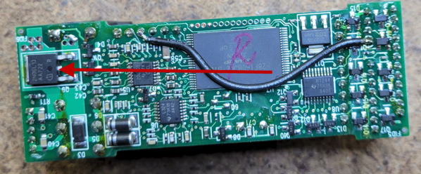
This is the underside of PS3 Board.  The two large square black units, Q201 and Q 309, are the FETS which will get the heat sink

5481

I applied Kapton tape over the components next to the FETS, so the heat sink can’t possibly short them out. It shouldn’t anyway, but no harm being sure

5482

I used Thermattach #411 to make good contact between the FETs and the heat sinks. It is essentially an etched aluminum sheet with adhesive applied to both sides

5483

It available from Digi Key.  This is what the Thermattach looks like.  In this photo one of the protective sheets has been removed, and the heat sink attached (DIGI-KEY #TGH-0220-04,  Aluminum Heat Sink 22 x 22 mm).  The heat sink has been trimmed to just cover the FETs and to clear the board carrier:

5484

The Thermattach was trimmed to match the heat sink, the other protective sheet was removed, and then the heat sink attached to the FETs.

5485

To encourage air from the fans to flow from right to left, I oriented the heat sink fins along the longitudinal axis.  In the photo above you can see the aforementioned Phosphor Bronze wire in place of the left hand slat.   Here is the board installed:

5486

You can see the finned heat sink attached to the factory supplied rectifier heat sink.  This side view shows the fans and the FTE heat sink right above them.

5487

Not the most optimal aerodynamically efficient design, I’ll admit.  But there should be enough airflow past the heat sinks…..

I had to install a main bus (made from two HO rails) to distribute AC power from the track:

5488

Connections are (from left to right): harness to the number boards (they are always lit and powered by one of those John Will LED drivers), AC to the DCS board, AC to the fan driver circuits, and AC power from the track via the pickups.   Obviously with this arrangement the fans are on whenever track power is applied. But I did not want to draw any more current through the PS 3 components than needed.  Besides, the fans are designed to be on all the time.

This is the other side, showing the fan wiring.  Note the fan rectifier is attached directly to the chassis. Not that I expect any cooling issues with only 0.4 A going through it.  You can also see the buck convertor that drops the 18 Volts DC from the rectified track power down to the 5 Volts DC needed for the fans

5489

And that’s about it.

I still need to put the shell on, but I don’t see any problems.  The Kohs has real photo etched cooing vents on both sides and both ends just like the real GG1, so there should be no problem getting the hot air out. If there is, I have two additional fans I can add to extract the air.

A few more notes:

  1. Per my original thinking. I found two high efficiency Faulhaber motors and tried them out. The good news is they dropped the current by about 0.3 Amps.  The bad news, they are substantially lighter than the Pittmans (a full 5.2 oz), so I had to add weight back to the chassis to climb an uphill curve. Which, you guessed it, caused the draw to go right back up to within a statistically insignificant range of the Pittmans.
  2. Readers may recall that the GG1 ran fine for several years,  and only recently started this stop/start cycling.  It was postulated that this may have been caused by the board going bad.  The real culprit is much simpler… I reversed the directions of my Sunset GG1-pulled Congo passenger train and this Kohs GG1 pulled passenger train. Running in this new “direction” the Kohs-pulled train had to traverse an uphill super elevated curve, whereas in the original direction the uphill was shallower and straight.
  3. When I installed the fans I hoped they would be loud enough to give the GG1 the sound of real blowers.   No such luck. They are too quiet.
  4. My sincere thanks to everyone who offered helpful suggestions, advice, and ideas in this thread.  Most notably
    1. Gunrunnerjohn
    2. GGG
    3. Harmonyards
    4. CentralFan1976
    5. Engineer-Joe

With that the saga ends, and I am ready to go on to less challenging problems.  Like developing a clean, plentiful, compact source of energy.

Attachments

Images (18)
  • 5492
  • 5474
  • 5475
  • 5476
  • 5477
  • 5478
  • 5479
  • 5480
  • 5481
  • 5482
  • 5483
  • 5484
  • 5485
  • 5486
  • 5487
  • 5488
  • 5488
  • 5489
Last edited by John Sethian

Irrelevant at this point since you solved the problem, but I'd think this would scare off anyone else thinking of using a PS2 or PS3 board to drive a non-MTH chassis.  I only scanned this thread and forgive me if I missed it, but I did not see discussion of the body-diode heat issue in the motor FETs.  That is, a motor current of 1 or 2 Amps should be NO SWEAT for the FETs MTH uses.  They are rated for tens of Amps!  How can they overheat with 1.4 Amps?

Answer: when pulsing FETs at high-frequency PWM like the PS2/3 boards, the so-called body-diode can actually warm up substantially since this diode turns on each motor pulse.  I'm not saying this is/was your problem, but I recall MTH modified the design of some higher power engines with an external body-diode.  Understood, this is techno-babble and has to do with the inductance of the motor windings and flyback energy in PWM circuits.  But when I read that this was being installed in a non-MTH motor chassis, the flag was thrown on the field.

Bottom line.  For the next guy looking at using a stock PS2 or PS3 board to drive a 3rd party motor/chassis, if you have a heat problem in the motor FET, consider using an external body-diode with lower power dissipation (such as a Schottky).  They are less than $1 and arguably less work than installing fans and heatsinks.

Another issue is the main bridge rectifier.  Many of the std-gauge engines use a tethered bridge to keep the diode bridge from overheating and causing excessive leakage which will kill the FET's.  Lots of early Legacy engines used a tethered bridge on the DCDS as well for the same reason.  Jon Z. mentioned this several times for the ERR products, he specifically told me that the limiting factor is usually the bridge rectifier.  I recently used the ERR Cruise Commander to drive the six motored K-line A-B-A set using a tethered bridge.  I used a 12A bridge and bolted it to the chassis for heatsinking, the FET heatsink on the Cruise Commander barely gets warm.

@gftiv posted:

As I Remember from my experience over 30 years ago, Shottky diodes have a very low reverse voltage rating. In an application with 18 VAC and lots of transients, They may not survive. Be aware of the problem.

Schottky diodes are available in higher voltage ranges nowadays, but they do still have lower reverse voltage ratings than traditional diodes.  Remember, Stan was talking about the internal Schottky diodes in the FET, so you're dealing with that limitation in any case.

Add Reply

Post
The DCS Forum is sponsored by

OGR Publishing, Inc., 1310 Eastside Centre Ct, Suite 6, Mountain Home, AR 72653
800-980-OGRR (6477)
www.ogaugerr.com

×
×
×
×
Link copied to your clipboard.
×
×