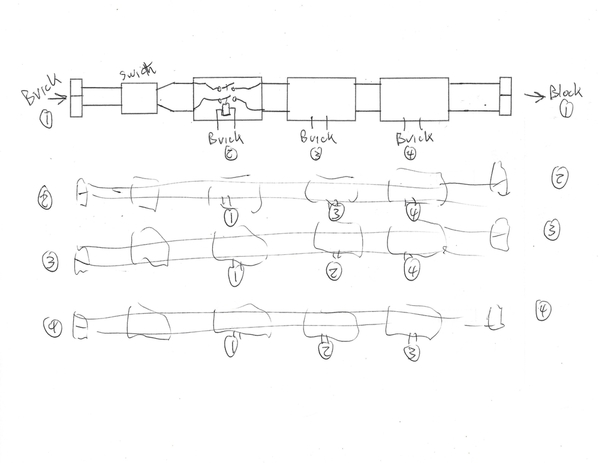
I am hoping somebody here can help me out for I don’t understand Relays and electrical stuff very well.I need help in putting safety relays in my layout I have 4 blocks in my layout. I would like to run pusher engines.So my problem is If my engine derails in block 1 block 2 needs to stop sending power. I have dcs also and 1 180 watt brick to each block. Can somebody help me. Thx and possible diagram that I could follow if possible thx again Rick
Replies sorted oldest to newest
As I see it, you need to define the qualifying event(s). Then, we can determine how to detect that event(s). And then what to do about it.
For example, if a pusher drives cars into a swan-dive from a lifted bridge, the cars are certainly derailing! You'd want to immediately cut power to the engine...but it is electrically difficult to detect that cars are derailing since the power to the engine does not change much.
If you (your eyes) are the detector in all cases, then I'd think pressing the DCS red E-STOP button is the simplest way to remove power to blocks.
So to use your example, the qualifying event is a derailment in Block 1 which should instantly remove power from Block 2. What if the derailment is in Block 2? Should this remove power from Block 3? Or if operating CW instead of CCW should this remove power from Block 1?
The relay part (removing power) is relatively easy. And relays are inexpensive...maybe a couple bucks per relay. We can provide exact wiring instructions. It's defining exactly what you want to do that's the issue...in my opinion.
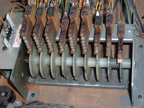
I had the same problem. Long trains with engines at both ends and across multiable blocks. I had a friend build this for me, this is above my pay grade. Works great, same system as you, DCS, 4 blocks and four bricks. All blocks shut down. So it is doable, just need someone to build this for you. This was built off site then installed.
PS when I asked this same question a few years ago on this forum I was told it can't be done.
Clem
Attachments
Clem, did you get a wiring diagram with that setup that you could share? Looks very interesting to me and just out of curiosity I'd like to see how it is wired, if that's possible. It might help the OP in duplicating the setup if it could also work for him.
I found these two OGR threads which I believe are what Clem K is talking about:
"can't be done" thread from 2015: https://ogrforum.ogaugerr.com/topic/track-blocks
"yes we can" thread from 2017: https://ogrforum.ogaugerr.com/...ong-trains-installed
Apparently, for Clem's system, the qualifying event is the breaker in ANY of the 4 bricks/blocks trips. This event is detected by the loss of voltage coming from that brick. The resulting action is power to all 4 blocks is removed. There are additional switches to reset/override this behavior.
I was thinking the problem might require coming up with a method to detect a derailment that does NOT cause a breaker to trip. That is, you want to quickly detect the derailment BEFORE it causes a problem (like a breaker to trip).
I do not have a wiring diagram, the gentleman that built it for me, just like some of you, likes to tinker around with electronic stuff.
clem
Need to add to posting I want all 4 blocks to shut down I would like something like Clem has
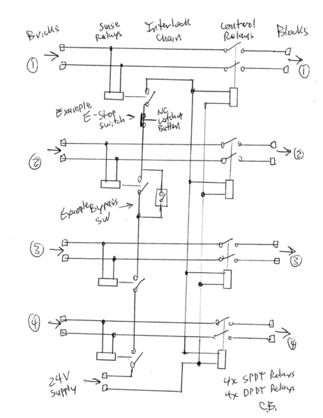
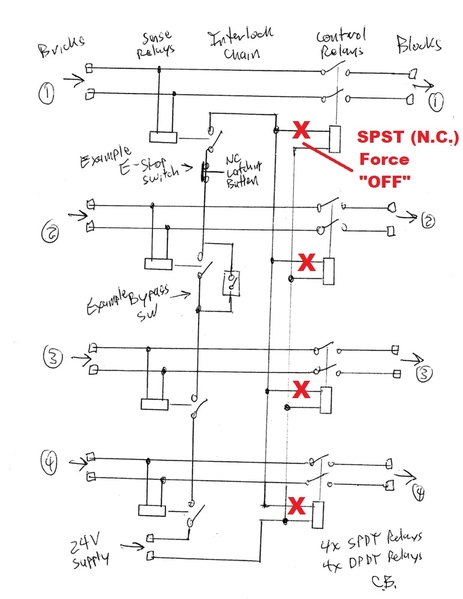
Here is a rudimentary circuit. There seems to more going on in the photo. The power for each block passes through a control relay. The set of control relays are driven by an interlock chain made up of a sense relay for each brick.
As shown, a bypass switch could be added to each sense relay to allow you to take that brick out of service. Also normally closed switches could be added into the interlock circuit to manually kill the blocks. These could be red mushroom buttons - they would need to be the type that latches where you twist the button to release it.
A small 24 volt ac power source is needed to drive the control relays. All relays are 24 V ac, assuming the 18 V from the bricks will work for these. Only Normally Open contacts are used on the relays.
Cam
Attachments
I was thinking sort of along those lines in the earlier threads Stan linked to, only I think I misunderstood the complete shutdown process Clem was wanting at the time. My thought with the working panel model in the picture was that it didn't seem to have enough relays? I am obviously still missing something here?
Maybe Clem's electronic friend will see this thread, have mercy on me and post a schematic for us...
Not quite clear why 12 relays are used in the photo. As Cam suggests, no doubt there's more going on than what's been posted.
Anyway, I like Cam's approach (8 relays). Should meet the requirements that have been so-far described.
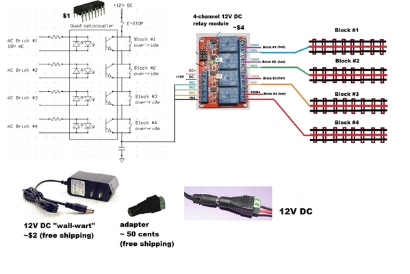
Here's a similar approach using 12V DC (instead of 24V AC) as the "control" voltage. I don't suggest this unless you're a determined DIY'er since it requires working with and soldering small components. But it can be done for about $10 out-of-pocket and only uses 4 relays. Again, this is posted in the spirit of kicking around ideas being that OGR is a discussion forum...
This uses low-cost solid-state optocouplers (vs. electromechanical relays) to detect the presence of brick voltage. The 4 optocoupler transistor outputs are connected in series so all 4 optocouplers must be triggered to present ~12V DC to the 4-channel relay module. This relay module is about $1/relay and the relays are 10 Amps. These are single-pole relays so this assumes the outer-rails of all the blocks are in common; Cam's diagram uses double-pole relays which switch both center and outer-rails. As Cam suggests, you can bypass/over-ride one or more bricks by placing a toggle switch at the output of the respective optocoupler.
Attachments
Has anyone thought of a way to sense when a car derails without tripping a breaker in the block?
I started with the premise of controlling both sides of each brick and not making any other connection. This is the most flexible but depending on how common is handled SPDT relays could be used to break only the hot side. The control relays must handle the full current output of the bricks. The sense relays only need to handle the combined current of the control relay coils. The sense relay coils are driven by the 18V brick outputs. The control relay coils could be any voltage, even DC. It would be possible to avoid the extra power supply by using one of the bricks.
Some time ago I sketched out a design to enable track power only if the TMCC signal is present. The command base was powered first. After a delay a relay turned on 120V to the bricks and transformers if the command signal was present. Then if the command signal dropped out the power was shut down. It used an Amperite time delay relay tube - I inherited a bunch of these in various voltages and delay times from a friend.
CJACK - Detecting a derailment that doesn't trip the breaker is a challenge. How to differentiate this from a normal current load. It might have to be a dynamic check looking for a sudden change in current? Maybe use a video camera with derailment recognition software. ![]()
PS when I asked this same question a few years ago on this forum I was told it can't be done.
Clem
Whats that quote, "When THEY say it's impossible or can't be done, someone in their garage is working on the solution" Or something similar to that effect....![]()
It's pretty easy to detect the command signal, the TMCC Buffer has a detection and monitoring circuit that shows signal strength. You could just duplicate that capability and add a relay to trigger the shutdown.
penn station posted:
CJACK - Detecting a derailment that doesn't trip the breaker is a challenge. How to differentiate this from a normal current load. It might have to be a dynamic check looking for a sudden change in current? Maybe use a video camera with derailment recognition software.
I was thinking maybe a short piece of rail outside each of the two outside rails for the wheel that's off the outside rail to bump against and trigger the shutdown...
John - I was thinking of hacking an R2LC. I could either just look for the 455kHz signal or do something with the detected command data. It would be connected directly to the base as I just wanted to see if the base was up and running. I am impressed with all your hard work on the buffer. Dale was a genius and it's hard to believe he is gone.
At one time I proposed making a TMCC receiver using sub-miniature tubes. I have loads of these in my vacuum tube collection. There is no valid reason to do this except, why not?
CJACK - that would work in some scenarios. Inside rails would probably work too. Perhaps use an accessory track.
I just found Dale's response regarding a tube based TMCC receiver. We were corresponding about the TMCC signal data encoding. This was from 2004.
You must be crazy!!  Glass bottles in TMCC?  Is that to get the full 'toob'
sound that so many of the recording studio people talk about?  Honestly, it
sounds like fun, but WHY??  Then again, you could try Nuvistors....
penn station posted:I just found Dale's response regarding a tube based TMCC receiver. We were corresponding about the TMCC signal data encoding. This was from 2004.
You must be crazy!!  Glass bottles in TMCC?  Is that to get the full 'toob'
sound that so many of the recording studio people talk about?  Honestly, it
sounds like fun, but WHY??  Then again, you could try Nuvistors....
Ah yes RCA Nuvistors, those tiny tubes in a tin can. Remember them well, especially since old tube testers didn't have those sockets so you needed adapters that plugged into a checker socket. Then there were the 10 (or was it 12?) pin glass bottles used in portable TVs...
Now I am showing my age. ![]()
Anybody remember the Raytheon CK722 Germanium transistor...?
cjack posted:Anybody remember the Raytheon CK722 Germanium transistor...?
Me, Me, ME!!!
My dad managed to locate one of them and gave it as a present (cost something like $4 in 1950s money). I then built a one stage audio amplifier attached to my Quaker Oats cylinder coil-cat whiskered crystal radio (later upgraded to a 1N34A germanium diode) to drive headphones. I then found plans to put in a transformer to drive a small speaker but the results were so so compared to headphones. I still have that little square can transistor somewhere as a memento to my electronics youth. Good old days.
cjack posted:Anybody remember the Raytheon CK722 Germanium transistor...?
My very first transistor, I bought one mail-order, as I recall it was pretty expensive, something like $6-7, a kings ransom in the 1950's! I was super careful with that part and built a few different circuits all the while following all the handling precautions. I finally broke a lead off right at the base and killed it, but by then more transistors were available at lower prices. ![]()
Rick R posted:…. I would like something like Clem has
The thread has meandered somewhat. Did you get the info you need?
Seems to me if you want what Clem K has, I'd think the individual who built it for him kept some notes and might be available to build another.
The first transistors I had were similar to GE 2N107. I now have two GE 2N107 and three Raytheon CK722 transistors in my collection. They come up on eBay occasionally. The blue CK722s are highly sought after.
I started with tube circuits. I built a Geiger counter using the Raytheon CK1026 Geiger-Muller tube, and a capacity operated relay using the Miller 695 coil. The CK1026 tubes are very hard to find. The 695 coils are near impossible. I've got several of each in my tube collection. Thank you eBay.
My first job out of college was with Raytheon, new CK series parts were still being released.
Ah yes RCA Nuvistors, those tiny tubes in a tin can!
yes I remember them they were used in the tv tuner when there was a mechanical tuner for television! that sure brings back memories!
Alan
The relay board in Clem's picture is very neatly laid out. The power flows from bottom to top with four similar circuits. A close up of the relays in each of the three rows and a shot of the back would probably be sufficient to work out the circuit. My first question is what to the toggle switches do?
Alan Mancus posted:Ah yes RCA Nuvistors, those tiny tubes in a tin can!
yes I remember them they were used in the tv tuner when there was a mechanical tuner for television! that sure brings back memories!
Alan
Tektronix used them in the input of the 454 oscilloscope. They drifted for about a half hour causing me to have to chase the DC vertical position of the trace. The 454A used fets and was much more stable.
penn station posted:The relay board in Clem's picture is very neatly laid out. The power flows from bottom to top with four similar circuits. A close up of the relays in each of the three rows and a shot of the back would probably be sufficient to work out the circuit. My first question is what to the toggle switches do?
Toggles turn the system off
clem k posted:penn station posted:The relay board in Clem's picture is very neatly laid out. The power flows from bottom to top with four similar circuits. A close up of the relays in each of the three rows and a shot of the back would probably be sufficient to work out the circuit. My first question is what to the toggle switches do?
Toggles turn the system off
There are 4 switches at the bottom of photo.
So to be clear, does each switch turn off (i.e., force OFF) 1 of the 4 blocks irrespective of the shutdown feature of your system?
And those are the ONLY switch/configuration controls to your "Safety Relay" system?
We're trying to help the OP here! In absence of diagrams/schematics/parts-lists from your custom built system since the OP wants what you have, I think we can get there if you let us know exactly what your system does. In my opinion that is...
What's the p/n for the optocoupler?
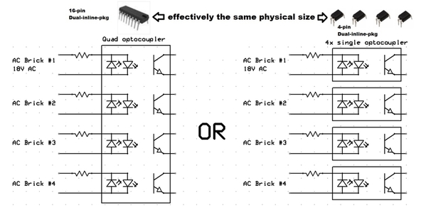
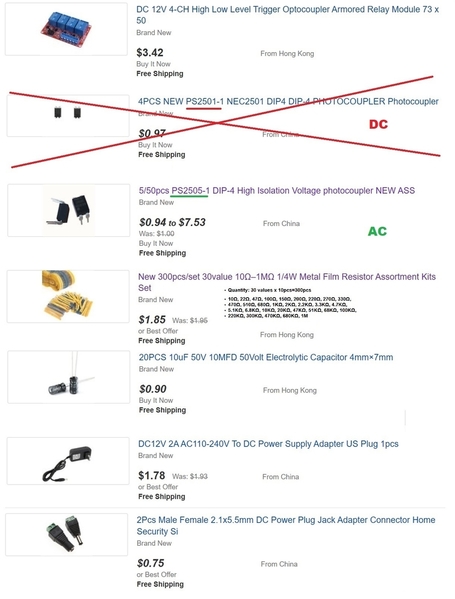
Just about any AC-input optocoupler will work. I just checked on eBay and for about $1 (free shipping from Asia), you can get 5 single-channel PS2505-1 optocouplers. You'd use 4 of them. Note that these devices come in 1, 2, and 4 channel packages and can be "stacked" so that 4 1-channel devices looks like 1 4-channel if that makes sense.
The PS2505-1, PS2505-2, and PS2505-4 are shown above from DigiKey though minimum shipping from DigiKey is over $4 these days.
As I type this out, I now recall and dug up a previous discussion about AC-input optocouplers:
https://ogrforum.ogaugerr.com/...89#69285198810032689
So I see there I recommended if only going to "stock" one optocoupler type in your DIY parts stash, use the AC-input LTV-8141. This part would work too. And it too comes in 1, 2, and 4 channel versions though their numbering scheme is LTV-8141, LTV-8241, and LTV-8441 respectively.
--------------
But as I stated earlier, you have to be a determined DIY'er. Some comments that may help or confuse depending on your comfort zone. I measured the input trigger current to the 4-channel relay module. Each trigger measured about 1 mA with 12V applied. So it takes 4 mA to trigger all 4 relays.
Each optocoupler is essentially acting as a bridge rectifier to convert AC to DC. Drive each optocoupler at, say, 10 mA. In other words an input resistor of 1K-5K. You need a capacitor to smooth the full-wave rectified output otherwise the relays might chatter/buzz at the line frequency. Something like 1uF - 10uF should work.
If someone/anyone is actually contemplating wiring one up I can peel additional layers of the onion; it may bring tears to your eyes ![]() .
.
Attachments
If it had universal appeal, it might even suddenly pop up with a circuit board design. ![]()
Here is a possible circuit explaining the 12 relays. From the photo each column covers one power channel. The brick power comes in at the bottom then flows through the switch and three relays in series. All the coil wires sneak through holes to the back. Clearly the magic happens on the other side of the board. My surmise is the relays are driven by the three "other" bricks in each channel.
I am still trying to sort out the terminal strip at the top. Also the red wire on the right side may mean the relay coils are connected to the track sections instead of locally on the back of the board.
Cam
Attachments
I agree that explains how 12 relays could be deployed...but I don't see how it performs any different/better than your 8-relay method. The force-OFF switch in your method could be placed on the output relays (red X) and these switches would not need to be heavy-duty 10-Amp (or whatever) switches.
Plus, with the presumed 12-relay method, the nominal condition is all 12-relays are "active". And for heavy-duty relays which might draw 1 Watt per coil... that's 12 Watts of overhead. OK, 12 Watts does not break the bank. But all 12 relays carry the full load current per block...whereas with your 8-relay method only half of the relays carry full block power so lower capacity relays can be used for the sense function so less expensive relays could be used.
In the absence of further information, I vote for your 8-relay method which AFAIK meets the known requirements.
Attachments
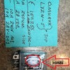
OK here are more photos, the toggles take that particular block off line, four toggles makes the safety feature total off. some of the fine wires on top of board go to micro pilot lights to tell which block tripped the circuit. the digital readouts for each block are...." I forgot".
This is hard to photograph. holding a flashlight ,camera and the board in position.and I don't like taking photographs because they always turnout poor.
Hope this helps the cause ![]()
Attachments
Stan - in my diagram the control relays need high current contacts. All the other relays and switches including the ones you added only need to handle to the current to the control relay coils. This was a quick sketch, I would probably select an lower coil voltage for the control relays like 12VAC, or perhaps DC - with the relay supply selected accordingly.
I agree with your comment on the power consumed by the always-on relay coils in both designs.
Clem - thanks for the additional photos. I love reverse engineering.
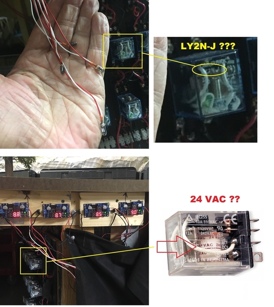
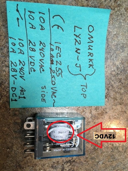
So for the record, could you confirm that all 12 relays are marked "LY2N-J" as it appears to be above?
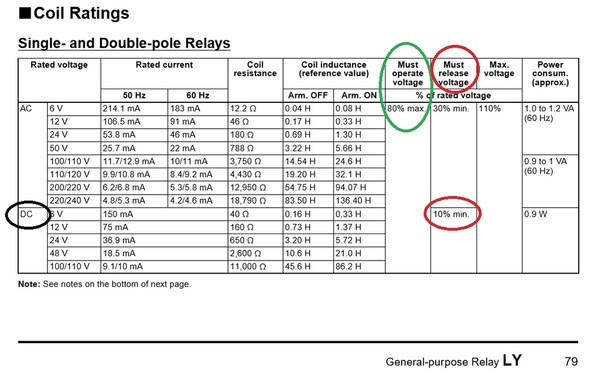
And, if so, could you read the marking on the coil wrapping. For example, in above the coil is repeatedly marked "24 VAC". This tells us the relay coil voltage...which for the LY2N-J type relay might be 12V DC, 12V AC, 24V DC, 24V AC, etc.
clem k posted:... the digital readouts for each block are...." I forgot".
Yes, this is a head scratcher. ![]() Those digital readouts are part of a DC voltage regulator module. It's not clear to me why DC voltage is being used - much less 4 separate DC voltages around 9V DC! Makes me think the relay coils are operating at 9V DC. Interesting!
Those digital readouts are part of a DC voltage regulator module. It's not clear to me why DC voltage is being used - much less 4 separate DC voltages around 9V DC! Makes me think the relay coils are operating at 9V DC. Interesting!
Attachments
Thx everybody giving me all the great information
I have to think this is killing gnats with a sledgehammer. Am I missing something? Why not just remove the 120V power from the layout with a trip, why all the high current relays? One big control relay on the input power and then any sensing you desire for the power districts.
stan2004 posted:I agree that explains how 12 relays could be deployed...but I don't see how it performs any different/better than your 8-relay method. The force-OFF switch in your method could be placed on the output relays (red X) and these switches would not need to be heavy-duty 10-Amp (or whatever) switches.
Plus, with the presumed 12-relay method, the nominal condition is all 12-relays are "active". And for heavy-duty relays which might draw 1 Watt per coil... that's 12 Watts of overhead. OK, 12 Watts does not break the bank. But all 12 relays carry the full load current per block...whereas with your 8-relay method only half of the relays carry full block power so lower capacity relays can be used for the sense function so less expensive relays could be used.
In the absence of further information, I vote for your 8-relay method which AFAIK meets the known requirements.
A few random thoughts-
Why couldn't you reverse the logic of the whole thing; use the NC contacts on the control relays and put the sense relay contacts in parallel? That way the control relays would normally be de-energized, no heating and no power consumption. Yes, if the control supply fails you would have no protection.
I'm guessing that the DC supplies were intended to permit the use of 12 VDC sense relays, but the filter caps in the supplies caused the sense relays to hold in for a while after the power was lost, so the 8.x volt setting was chosen to put the relays right on the edge of dropout to speed up the response to a power loss.
Because there are no inexpensive 18 VAC relays, the sense relay function is going to require a bit of fudge. I think the original design is a good attempt to use plain old stock parts.
I understand that the builder of the original unit may well have used what he had on hand. No criticism of the original design is intended.
Just talking........
gunrunnerjohn posted:I have to think this is killing gnats with a sledgehammer. Am I missing something? Why not just remove the 120V power from the layout with a trip, why all the high current relays? One big control relay on the input power and then any sensing you desire for the power districts.
That's a good thought too.
gunrunnerjohn posted:I have to think this is killing gnats with a sledgehammer. Am I missing something? Why not just remove the 120V power from the layout with a trip, why all the high current relays? One big control relay on the input power and then any sensing you desire for the power districts.
I too may be missing something but isn't that a Catch-22 situation? That is, if you remove 120V AC to all 4 bricks then obviously all 4 brick outputs immediately drop to 0V (including the brick that is already at 0V from its derailment trip). Now there is no indication of which brick tripped in the first place. I think it's kind of neat how there are 4 "micro pilot lights" that run to the top of the board that directly indicate the status of each brick/block.
OTOH, I suppose one could say it's obvious by looking at the layout to see which block caused the problem, feel each brick's reset button to see if popped out, etc..
Then, after MOW clears the derailment and resets any brick breakers, how do you "restart" the safety circuit? That is, all brick outputs are now 0V so the sensing devices are continuously trying to remove 120V AC. I suppose it could be as simple as a momentary bypass switch...but, as they say, the devil's in the details.
PLCProf posted:...I'm guessing that the DC supplies were intended to permit the use of 12 VDC sense relays, but the filter caps in the supplies caused the sense relays to hold in for a while after the power was lost, so the 8.x volt setting was chosen to put the relays right on the edge of dropout to speed up the response to a power loss.
...
Just talking........
Agreed. We are just talking. ![]()
So if these are indeed the LY series relays, note that for the 12V DC version it Must Operate at 9.6V and Must Release at 1.2V. I think that would be walking quite the fine line (i.e., delicate balancing act) to trim the DC voltage to 8.7V, or 8.8V, or 8.9V, whatever to drive a 12V DC coil that will hold until the capacitor drops to what could be as low as 1.2V!
Practically speaking, other than ASAP, how quickly must a safety system respond to one brick tripping? Given momentum, if you instantly remove power the consist might nevertheless coast several car lengths...and of course the prototypes much further without dynamic braking. So for a model train setup, I'd think maybe 1 second is a reasonable goal? That is, consider a human operator visually watching. A derailment is detected. Now, in a panic, find the E-stop button on the remote fob which was supposed to be hanging on your neck but in all likelihood left somewhere because you had meant to change the battery! ![]() .
.
Attachments
stan2004 posted:gunrunnerjohn posted:I have to think this is killing gnats with a sledgehammer. Am I missing something? Why not just remove the 120V power from the layout with a trip, why all the high current relays? One big control relay on the input power and then any sensing you desire for the power districts.
I too may be missing something but isn't that a Catch-22 situation? That is, if you remove 120V AC to all 4 bricks then obviously all 4 brick outputs immediately drop to 0V (including the brick that is already at 0V from its derailment trip). Now there is no indication of which brick tripped in the first place. I think it's kind of neat how there are 4 "micro pilot lights" that run to the top of the board that directly indicate the status of each brick/block.
I don't see this as a problem. Your detection circuit could be independently powered and maintain the status of the trip, but the main layout would all be killed with a single power control. I'm just at a loss why I need a ton of high current relays and the associated wiring and complexity if I want to shut the whole thing down anyway on a sensing circuit failure alert.
What I wanted to show is how the sense relays and relay logic* could be used for an interlock chain. In logic terms it is and AND gate. Outputs are enabled if Brick 1 is on AND Brick 2 is on AND Brick 3 is on AND Brick 4 is on.
Since the control relays interrupt the power to the track, the bricks are still powered. If you have a pilot light on the output of each brick you will see which ones that are on.
The sense relays could be replaced with simple sense circuits on each brick. Optocouplers would allow the logic be done using low voltage DC that drives a single relay which in turn drives the power relays or with suitable output drive could control the power relays directly. There are endless approaches here.
Controlling the 120V power only requires one control relay and it operates at lower current. You do need to deal with 120V though. There are prepackaged relays from controlling appliances so you don't have to deal with 120V - but I don't know if the right specs would be available. Driving four fully loaded 180W bricks would be 720W. That is 6 Amps on the AC side. If you don't expect to use that much on average you could use a 5 Amp relay but you'd need a circuit breaker to protect the relay contacts.
With the 120V approach the system will latch in the off state when it shuts down. Also it will power up in the off state so you do need a Start switch after power up or to reset. If you have a power failure the system will be off when power returns until you press the Start switch - this is an added safety feature.
If you start using normally closed contacts you can avoid relays being constantly energized. However you will lose the fail safe aspect of the relay power supply failing. But if you stipulate the relay power supply will be on you can take the NC approach.
*Relay logic - I have an EM (electro-mechanical) Space Odyssey pinball machine from 1976. EM pinball machines are all relays, switches and solenoids. These machines have a score motor, essentially a washing machine timer switch on steroids, that turns until certain conditions are met. The score motor is what makes the score roll up multiple steps on one switch closure. Mine has a common problem where the score motor does not stop running. Debugging this is no easy task. The schematic is a ladder diagram (one way of showing relay logic) - it is 4 feet wide.
Attachments
To Stan's earlier point about the original question. These approaches address the problem of shutting power to all blocks if one brick trips. Does this in itself adequately solve the pusher problem?
Tried to take photos of relays, but no luck. to much glare, tiny printing on clear background, I have extra relays so i took those out side still no luck with photos. Soon you have to trust my poor eye site, and and no short term memory to wright things down correctly. There is two different brands of relays, Taking a long time to type this, ill wright it down and take photo.
Well this message took over 45 minutes and still not sure of what I wrote and got the photo standing on end. Sure wish you guys would just stop by and look at it. There is some wiring diagrams on it also, good luck in copying that down.
Attachments
The circuit of for this type of relay is simple. Looking at the base with the the two vertical terminals at the bottom: the vertical terminals are the coil. The horizontal terminals are the contacts. You can see how these directly exit the base of the relay. The top terminals are Normally closed, the middle terminals are the normally open. then the movable contacts. One pole is on each side.
This is an Omron part. I have attached a datasheet. The part number should be something like LY2N-xx where xx is the voltage.
I can find the LY2N-J part numbers on the web but haven't determined this significance of the suffix.
(Forgive all earlier versions of this post - not having a good day.)
Attachments
Glad it helped ![]()
penn station posted:Since the control relays interrupt the power to the track, the bricks are still powered. If you have a pilot light on the output of each brick you will see which ones that are on.
Depends on the brick, the Lionel PowerHouse 180 light doesn't go off when the breaker trips, for instance. In any case, simply having the control logic remember the trip condition solves that problem. ![]()
penn station posted:*Relay logic - I have an EM (electro-mechanical) Space Odyssey pinball machine from 1976. EM pinball machines are all relays, switches and solenoids. These machines have a score motor, essentially a washing machine timer switch on steroids, that turns until certain conditions are met. The score motor is what makes the score roll up multiple steps on one switch closure. Mine has a common problem where the score motor does not stop running. Debugging this is no easy task. The schematic is a ladder diagram (one way of showing relay logic) - it is 4 feet wide.
FWIW, I used to own a bunch of pinball machines and in high school I worked at a pinball and jukebox supplier fixing the machines. I had to fix all the pinball machines I had later in life, that's how you get them cheap! I had some of the relay models and a few of the electronic models. There are tons of Internet sites dedicated to pinball repair, and you can get a bunch of expert help if you look around. The fact that you have a a schematic of the logic is a huge plus, that should make it tons easier to track down your issue.
clem k posted:….There is two different brands of relays, Taking a long time to type this, ill wright it down and take photo.
Clem, the 2nd photo is exactly what I was looking for. Note that the relay coil white wrapping (inside the plastic case) says 12VDC (upside down in photo).
But when you say two different relays, I wondering if some of the coils are printed with something other than "12VDC" or just two different brands of the same 12V DC relay. I appreciate the time you've spent scurrying around gathering photos and such!
Again, getting back to the matter at hand. You have a system that works and have been kind enough to share what you have in response to the OP. Practically speaking, I think it's unlikely that the OP will be able to exactly duplicate your configuration.
At some point "we" need to agree upon exactly what this gadget has to do and come up with a complete parts lists and wiring diagram. Many different ways to solve the problem. It's just that all ideas eventually degenerate into actual work, and Nothing is so easy as the job you imagine someone else doing.
Attachments
Stan, I am trying to imagine the easiest solution. ![]()
John - Yes I have a good EM repair guide. I also have a Williams Whirlwind (1990) with System 11 electronics.
Well, Clem apparently has a buddy who built it off-site and it just showed up plug and play. Doesn't get easier than that.
As I see, there are 2 things going on here.
Thing 1 is a general discussion about what features might be useful in a safety relay system and how one might go about implementing it...using Clem K's system as the proverbial dart board.
Thing 2 is the specific task of building a system for the OP where at this point there are still some TBD requirements and logistical unknowns. Who exactly is building this? Is soldering and working at the component level OK? Budget? And so on.
Stan........ he will need someone to build this.... or get all the correct parts and an excellent diagram. I could work with him on this so very clear simple directions are needed and the correct components. Like I told him I could take mine off layout and copy it, but I would not bet it would work, or the original (mine) would work again.
Stan same relays two different brands? Hard to read printing. Here is what I think s on the other one.
CLION
HHC68A-2Z
JDX-13F LY2
THEN SOME WIRING DIAGRAMS I CANT MAKE OUT
10A 240VAC/28VDC
MORE STUFF I CANT MAKE OUT, I THINK BRAND NAMES ?
Ps lighting seems better, I can read easier now.
Attachments
If we're at the point of Thing 2 - actual implementation - then it's a matter of who exactly is going to do the work.
Again, there have been several proposed alternatives in the Thing 1 category. The actual material cost is quite modest. The relays WITH socket are a couple bucks each (no soldering required). Toggle switches with screw-terminals (no soldering required) are about $1. Screw-terminal barrier strips (no soldering requried) are also modestly priced. DC voltage regulator module with digital LED voltmeter are about $2 (no soldering required).
So taking a somewhat cynical view of the matter at hand, the material cost for all the proposed variations/alternatives will be small compared to "labor" even at minimum-wage whatever that is these days!
Attachments
Since I live close to the OP I'm willing to help with the build, However that means, myself or the OP will probably be asking a lot of questions here.
First question, what gauge wire ?
Clem
For the track power stuff, at least #14 I would expect, that's good for 10 amps. For short runs between relays and the like, you can get away with a bit smaller wire.
One thing interesting that Dale M mentioned back awhile is that the wire tables for wire gauge are designed for 120 vac and 240 vac. The issue is that there is an allowable voltage drop as a percentage of the line voltage. When the line voltage is only 18 vac then that voltage drop which was ok for 120 vac is too much for an 18 vac circuit.
I always compute actual wire drop when I'm working on wiring for train layouts. For short runs, it's a bit less critical as the current carrying ability of the smaller wire normally isn't in question, but it's the voltage drop at the max current it'll see.
Good I have a lot of 14 gauge,
I searched for a packaged power control relay. I found this controlled power strip. The control input operates from 3-48VDC or 12-120VAC. It has 2 normally open outlets, 1 nomally closed, and 1 always on. It controls up to 12 Amps. This avoid the need to work with high voltage wiring.
This could be used to control the power to the bricks. The brick outputs could be monitored with optocouplers and a few other components, plus a reset switch. The input resistance of the control terminals is not specified. Based on examples it does not require much input current.
The price is $27 at site is https://dlidirect.com/products/iot-power-relay. Could be useful for other applications. It can be used with an Arduino for example.
Attachments
Reminds me of those power outlets that turn ON at dusk and OFF at dawn. About $10 at Home Depot:
The Thing 1 idea is to make a simple circuit that monitors the 4 brick outputs and turns ON a "fault" bulb or LED if one or more bricks trips its breaker. This "fault" lamp would be placed against the outlet light sensor. Ta da! When the bricks are all working, the fault light is OFF and the outlet thinks it's night-time and turns on. If any brick trips the fault light is ON and the outlet thinks it's day-time and turns off. This widget only has 2 AC outlets so a 4-outlet power strip could be used to power 4 bricks. Other similar light sensing strips have more outlets but I figure the existing bricks are probably already connected to a multi-outlet power strip.
Attachments
Would either one of these do the job we want done ? cutting track power to all four bricks if one trips ?
Yes. The proposed method of cutting wall-outlet 120V AC voltage to all 4 bricks is another alternative. These controllable power outlets usually have a relay inside but as pointed out, you don't have to mess with high-voltage wiring.
But again these controlled outlets are a Thing 1 discussion item...not a Thing 2 solution.
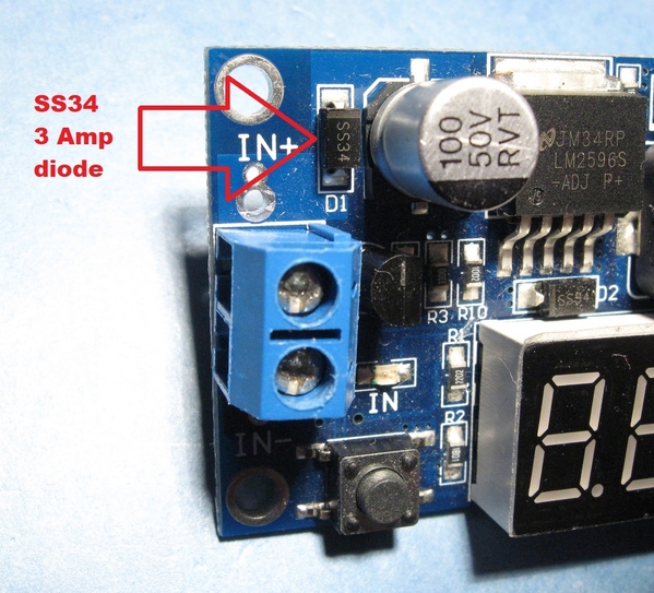
Anyway, along the lines of Thing 1 discussion, it may not be common knowledge that many of the DC-to-DC converter modules have a reverse-protection diode on the input. Here is a close-up of what I believe is the DC-to-DC module that Clem has:
What this means is you can apply 18V AC brick voltage to these modules. And for low power applications, then the half-wave rectification and modestly sized input capacitor (100 uF shown here) might just do the trick! It might even turn out that ~9V DC (average) was all this module could put out when driving multiple 12V DC relays! I was wondering where the diodes and/or bridge rectifiers for AC-to-DC conversion were in Clem's various photos and this is what I came up with. Again, this is Thing 1 "just talking..." ![]()
Attachments
Seems to me just one of the above pre made controls is the way to go. Just plug the bricks in ?
K.I.S.S. certainly applies here, switching the 120V always made more sense to me for the intended result. ![]()
Some how this won't be as easy as it seems, so could someone print exactly which components to use and how to connect them.
Thanks
stan2004 posted:Not quite clear why 12 relays are used in the photo. As Cam suggests, no doubt there's more going on than what's been posted.
Anyway, I like Cam's approach (8 relays). Should meet the requirements that have been so-far described.
Here's a similar approach using 12V DC (instead of 24V AC) as the "control" voltage. I don't suggest this unless you're a determined DIY'er since it requires working with and soldering small components. But it can be done for about $10 out-of-pocket and only uses 4 relays. Again, this is posted in the spirit of kicking around ideas being that OGR is a discussion forum...
This uses low-cost solid-state optocouplers (vs. electromechanical relays) to detect the presence of brick voltage. The 4 optocoupler transistor outputs are connected in series so all 4 optocouplers must be triggered to present ~12V DC to the 4-channel relay module. This relay module is about $1/relay and the relays are 10 Amps. These are single-pole relays so this assumes the outer-rails of all the blocks are in common; Cam's diagram uses double-pole relays which switch both center and outer-rails. As Cam suggests, you can bypass/over-ride one or more bricks by placing a toggle switch at the output of the respective optocoupler.
Hey Stan 2004 I like this and so does my son Likes this system. Can you send me a drawing from bricks to optocoupler? If its not to much trouble. Need to peel onion a little more, Thx for your help
Rick R posted:...Hey Stan 2004 I like this and so does my son Likes this system. Can you send me a drawing from bricks to optocoupler? If its not to much trouble. Need to peel onion a little more, Thx for your help
Are you saying you're going to dive into the deep-end of DIY component assembly, soldering, etc.?! ![]()
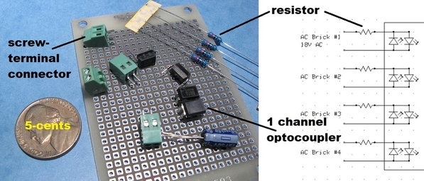
The connection(s) from each brick to the optocoupler is thru a ~5-cent resistor and possibly a ~15-cent screw-terminal connector to make wiring neat. I would mount the components on a ~50-cent prototyping board as illustrated above. As mentioned above, if using the optocoupler it appears cheaper to buy 4 1-channel optocouplers (~25 cents each) than 1 4-channel optocoupler. The behavior will be identical.
Note that you can use this optocoupler method to drive the IOT relay widget you bought too. As I've mentioned before it all comes down to EXACTLY what features you want - for example over-ride switches, status lights, and so on. You said you want what Clem has; I appreciate that but we really don't know exactly what Clem has and I'm not the guy that will ask him to dis-assemble his system, take photos, etc.
Attachments
stan2004 posted:Rick R posted:...Hey Stan 2004 I like this and so does my son Likes this system. Can you send me a drawing from bricks to optocoupler? If its not to much trouble. Need to peel onion a little more, Thx for your help
Are you saying you're going to dive into the deep-end of DIY component assembly, soldering, etc.?!
The connection(s) from each brick to the optocoupler is thru a ~5-cent resistor and possibly a ~15-cent screw-terminal connector to make wiring neat. I would mount the components on a ~50-cent prototyping board as illustrated above. As mentioned above, if using the optocoupler it appears cheaper to buy 4 1-channel optocouplers (~25 cents each) than 1 4-channel optocoupler. The behavior will be identical.
Note that you can use this optocoupler method to drive the IOT relay widget you bought too. As I've mentioned before it all comes down to EXACTLY what features you want - for example over-ride switches, status lights, and so on. You said you want what Clem has; I appreciate that but we really don't know exactly what Clem has and I'm not the guy that will ask him to dis-assemble his system, take photos, etc.
Yes My son and I are going to try. I sent the Iot relay back thx for help My son is going to school for controls engineering So we need diaghrams to go by, The optocouplers are new 2 him. and me.So Me, Erick my son and Clem are on a learning project
I don't know if this is what you mean by a "diagram" but see if this helps.
To be clear this uses the method of switching the "hot" brick power. It is assumed that all the brick commons and track block outer-rails are tied together.
I found the following items available now on eBay though these have the 2-3 week delay from Asia. I'm sure all these items are available domestically (Amazon, eBay U.S. sellers) though my experience is this double or triples the cost. As shown it looks like between $10-15 not including wire.
The electronics operates on 12V DC supplied by a wall-wart so you obviously need an available wall outlet. IF this is a nuisance, an option is a ~$3 AC-to-DC converter module that would convert 18V AC from one of the AC bricks into 12V DC. For example:
Everyone has there favorite way to assemble electronic circuits so to each his own. One way is to use so-called prototyping board which has solder-able holes on a 0.1" (2.54mm) grid. I show below the use of an IC socket for the optocouplers. This way you solder the interconnection wires to the socket and not to the IC terminals. The current flowing within the board is very small so something like #30 gauge solid would work fine. It's also negligible current flowing between the bricks and this board, and this board to the relay module so thin wire can be used too. Practically speaking these interconnections would use, say, #24 or #26 gauge or whatever you have lying around for hook-up wire.
I suggest using 2-pin screw terminal blocks on the board: (4) on the input side from the 4 AC bricks, (1) to provide DC+ and DC-, and (1) for the trigger signal to the relay module.
I also don't show the use of terminal blocks, wire nuts, or whatever hookup method to distribute brick power as that's dependent on your layout and what you use today.
If you're using Clem's system as a model, I see he has some indicator/status lights and toggle switches to bypass/over-ride the safety shutdown function. We can explore exactly how those would integrate or if you even need/want them. First though, I suggest contemplating the above to re-affirm your decision to jump in.
But to your point, if your son is going into Controls Engineering, he and optocouplers will soon become BFFs. ![]()


