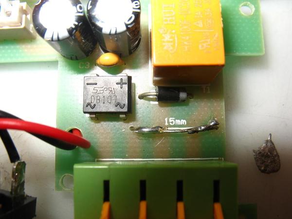
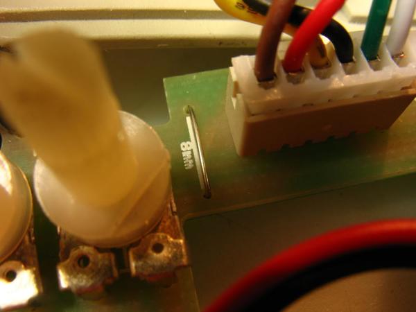
I was helping a friend swap a 153IR on my layout last night. I had the 5 wires laid out in order above the hole in the layout. His job was to attach them to the contacts. His hands slipped on the wires and when I saw it, I thought the order was changed, but he thought he got it right. Wrong. We connected it up and....fried. I opened it up and found what looked like a wire through hole mounted on the board that was melted. There were actually 2 of them.....one marked 8mm and the other (melted) was 15mm. As I had nothing to lose and not knowing what that "wire" is, I stripped a length of wire that seemed to have the same gauge, measured a piece 15mm long and soldered it to the melted pieces. Still didn't work. A couple of questions......first......what is that wire like component?  Second......nothing else looked fried. Any ideas?

Roger

Original Post

Replies sorted oldest to newest

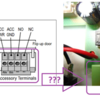
If this diagram from the 153IR manual matches the photo, the 4-contact connector has the AC power on the 2 left contacts and relay outputs (NO and NC) on the 2 right contacts.  In which case that 15mm jumper wire appears to simply jumper AC power to the relay contacts (yellow component?).  If this is what's going on it's hard to understand why the unit no longer works if you repaired the 15mm wire.  In other words, what's there to "break" even if you mis-wired it?

Can you hear the relay click when you activate the occupancy sensor (put your hand or whatever in front of the beam)?  Presumably the unit was previously working. 

153ir

Attachments

Images (1)
  • 153ir

Hi Stan,

I don't know if it was previously working as it's brand new. I say that facetiously because my experience with them has been that I've had a bunch that don't work out of the box. If it does work, it seems to not break down over time. In fact, this one was a replacement for the one I received last week which was dead out of the box. They exchanged it and sent me this. 

The photo does not show everything that is on the board.   There's also the possibility the infra red "eye" is non functional. And there is no "relay click". But I see no evidence of other "damage" in there.

Roger

If the 15mm wire is the only thing that failed I don't think it affected the low-voltage electronics.

Are you interested in attempting a DIY fix/repair? 

For example, with your digital camera you should see a purple glow from an active Infrared LED. 

IR LED glow

The lettering on the yellow relay, suggests it is 5V, so I'd bet there's a 5V DC power supply; should be fairly simple to confirm 5V is present.  Etc..

hk4100f relay


Attachments

Images (2)
  • hk4100f relay
  • IR LED glow

Stan,

I was downstairs working on it before your message came up. Yes.....I'm always up for a DIY......you helped me on my reverse unit earlier.  But here's what I discovered in tinkering just now. I took all the boards off the frame to check to see if anything (components or traces looked burned). Nothing. Then I tightened up the two harnesses. The use for this one was going to be a Gateman variation, so I had the first three outputs (from left to right). I wasn't getting a click. But just for the heck of it, I measured the voltage output on the first two....access power, access ground.  15V.   Measured the third (which is NO) with the access ground after running my hand in front of the "eye".  15V (very, very faint click....almost inaudible compared to my others). So......I'm thinking it should work. Thing is.....before I run my hand in front of it, I measure 6V from access ground and NO. Normal?

I can't go back down for a couple of hours, but I will try your suggestions above. But first I want to swap this one out with one of my others that is also operating a Gateman.  The couple of times I tried that, I got no response.  But I'm thinking I should now.  I'll post back when I get a result later

Roger

ROGER1 posted:
...Thing is.....before I run my hand in front of it, I measure 6V from access ground and NO. Normal?

Possibly.  A typical DMM might have an input resistance or, say, 10 Million Ohms which negligibly burdens the measured circuit/voltage.

If there is any residual solder flux (or whatever) on the circuit board between the ACC PWR voltage and the NO contact, there is a high resistance path that can be measured as a stray voltage.  For example, if this stray resistance was 15 Million Ohms, that would create a voltage divider with the DMM input resistance such that 15V AC would "leak" through to the NO contact and read as 6V on the meter.


Well, it fried again. The good news is.....it was working. I alligator clipped it up, the light went on in the Gateman and the door stayed open. Then I smelled smoke. LOL    I think the contacts shorted underneath as the chassis was off it. But.....I think it was isolated to a small capacitor. There are three little ones in there......104 written on it. They are not can shaped.  Tan tear drop. The third one which fried is not unreadable, but I think it's the same one. There are 2 220uf cans behind it. I was thinking of removing them to get a reading on them as they read 0 connected to the board. But that little cap is gone. I think it was a harness problem as the door did open before it cooked off.

Roger

No......not the accessory. I have a separate transformer bringing power to my accessories......2 busses from a KW. So power was off to the track. I clipped up the bad 153 to the wires that controlled a functional 153 which controlled a Gateman. However, I thought I had insulated the whole bottom of the board and laid it on the track as there was no room anywhere else and the track power was off. But.....obviously, the rails are conductors and a rail must have contacted an exposed part of the underside of the board.      I'm thinking I want to get a new cap and try again. I'm thinking this is a non-polarized cap. Correct?

Well, here's what I discovered last night. I found a 104 on a circuit board from an old accessory I scrapped for parts. Installed it and it was fine, but the bridge rectifier in front of it was the real culprit. Melted underneath.  I didn't have one that small, so I removed it and alligator clipped a big 6amp one that was part of the order I placed when adding them to Williams engines. Powered up and.....no heat and nothing was frying. I got voltage output on Access Power and Access GND. But the infra red "eye" was not triggering the NO.  As I mentioned, that seemed to work again after fiddling with it, but doesn't now. I'll give it another shot later as it got too late.

Wired up the bridge rectifier again and checked power in and power out. The NO switch does not seem to work with the light sensor. No click of the relay. As mentioned, I replaced the 104 cap. The light sensor board appears to have no damage. I'm thinking maybe I should get another relay. I can't seem to locate it on DigiKey website. If I can find it, maybe I'll order the original rectifier and the relay. I'm not finding any other damage. Although, I can' seem to repeat your photo of the infra red "eye" glow. 

Roger

Can you post additional photos of the circuit board?  Somewhere there ought to be a 5V regulator IC chip.  That would be a simple thing to check (for presence of 5V DC).  If you're looking for that actual "original" rectifier, the marking in your photo says DB107 which is a common part.  For example, 43 cents at DigiKey.

If messing around, try that digital camera aimed at the MTH IR window to see if you get the purple-glow.  Also, if messing around I'd think you could aim your TV IR remote at the window and trip either the Lionel or the MTH sensor.  In other words, this might be a way to test if you have a broken IR emitter.

Like GRJ says, measure if you get 5V across the relay coil when you are supposedly tripping the sensor (with your hand or whatever).  Of course you need 5V DC present in the circuit as mentioned above; IIRC in at least one version of the 153IR there's a common 7805 3-pin regulator IC chip which, if used in your version, should be easy to locate and measure.  I see that relay on eBay for less than $1 shipped...

hk4100f relay on ebay


Attachments

Images (1)
  • hk4100f relay on ebay

Stan,

A few things......I had found the rectifier on DigiKey but was unable to locate the relay.  I'll take the info off the Ebay listing as I have to place a DK order anyway (need other things). The main board does not have the 5V regulator.....not a lot there. However, the IR board is much more complex and I'll look there. The 5V regulators I've worked with a fairly large compared to what I saw on there, but I'll look again later when I check the voltage on the relay coil.    I suspect something is wrong with the IR. The one I originally ordered 2 weeks ago (and I sent back) did not work out of the box. No relay click and it didn't trigger the NO switch. I'm thinking this one has a similar issue. Won't send this back, though as I've burned it and cannabilized it. LOL   This will be for practice.

Also, with the digital camera.....photo with flash or flash off?

Roger

Ok......did some tests.   I tried the camera with my TV remote and saw the glow.  Didn't have to take a picture.....saw it in the screen.  I didn't see it with the 153.  I tested the contacts on the relay. I wasn't sure if it should be constant 5V or just when triggered. But aside from what I thought was a spurious 6V reading, I got nothing there. But I did put the meter on the diode next to the relay and got 4.9V.   Below is a pic of the IR board. I'm not recognizing a 5V regulator. See what you think. IMG_0028

Attachments

Images (1)
  • IMG_0028

Interesting in seeing the evolution of these widgets.  Here are some photos from an earlier thread on 153IR repair showing previous revisions of what appear to be the same two boards.  On these boards there's a 3-pin 7805 5V regulator IC to the right of the adjustment knobs.  I would have thought since they retained the 2-board design that 5V DC would still be generated on the board of your first picture - and that 5V DC would be piped to the board with the IR emitter/detector over that 6-wire harness...but who knows! 

IMG_2187%20-%20Copy

IMG_2191

Anyway, if not obvious, the emitter (or what I'd think might glow purple viewed by a digital camera) is the clear lens component.

IMG_0028

Attachments

Images (3)
  • IMG_2187%20-%20Copy
  • IMG_2191
  • IMG_0028

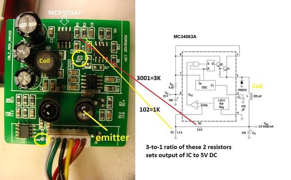
The LM567CM is a good number and makes sense for a pulsing IR detector; I can actually make out that number from your photo.  But that MC3406 is an odd marking - could it actually be MC34063A if it's the part shown below?  If so that would make sense as a voltage regulator IC chip.  In which case perhaps this version pipes the higher track level voltages on the harness and generates the low-voltage (5V) DC on the IR board.

GZ407 is a mystery.  Seeing as to how I can make out the LM567CM, I wonder if you tilt the camera at just the right angle if you can show those markings.  I might be able to identify the manufacturer logo or something that would help.

IMG_0028

Also note circled in yellow are two test points "5V+" and "GND".  Unless they are being particularly coy, I'd think you should measure 5V DC between those two points.

Attachments

Images (1)
  • IMG_0028

Stan,

I checked a number of things from your post.  You are correct about the MC chip. There's a 3A at the end. I did see that but didn't realize it was part of the part #.  On the GZ chip there's another line of lettering above.     741C         And before the 67407 it says      ST

But I think what is most telling.....I measured the voltage at the "test points".        0V        Not good

That makes sense now - it's undoubtedly the MC34063A which is a voltage regulator IC... less than $1 at Digikey.  You'll pay more for shipping so I suppose wait until you have other stuff to order seeing as to how you have a working MTH ITAD to keep the revenue rolling on your railroad.

It looks to be essentially a "textbook" configuration where the MC34063A is surrounded by a half dozen or so components; the following diagram is from the datasheet.  I suppose you could follow the board traces to draw out the circuit but the tell-tale is there are 2 resistors that set the output voltage.  When the resistors are in the 3-to-1 ratio, this means the output voltage is being programmed to 5V DC so that pretty much confirms its role in life.

Replacing that 8-pin surface mount component can be tedious and everyone has there own soldering technique...one of which is to let someone else do it!    Anyway, I suppose one of the supporting components could have failed, but if you are measuring DC voltage going in, and nothing coming out, then I'd suggest it's just as expedient to replace the chip rather than trying to analyze how the circuit works. By DC voltage going in, that would be from the bridge-rectifier on the other board...and you should measure, say, 18V DC or so on the Vin (input) pin relative to GND if powered from 14V AC Accessory voltage.  Vin is on pin 6 of the IC chip.

IMG_0028a

P.S. the pin assignments as drawn in their diagram is mirrored which might be confusing.  Here's the pin assignment should you choose to probe around the chip itself.

mc34063a pins

Attachments

Images (2)
  • IMG_0028a
  • mc34063a pins
Last edited by stan2004

Well, it would be pretty cheap if I was just replacing the Bridge and this chip (if that's all I replace). I already swapped out the 104cap.   But getting that 8 pin chip off is harder than soldering one on I think. Not sure how I could get heat to many pins at once.....enough to lift off one side. One at a time won't do it. Unless I cut it off with my flush cutters (like I did with the old bridge) and remove the pins one at a time. 

You don't try to heat them all at one time.  For taking those off, I use a pair of small "nippers" and just cut the leads next to the chip body.  Then you can just sweep the left-over leads off with the soldering iron after the chip body is out of the way.

To solder the new one on, start with one let in a corner and just use the tweezers to align the chip to the pads and remove the heat.  Then you can tack down and opposite corner and finally work your way around soldering the rest of the leads.  There's some other methods for finer pitch parts, but this one has enough lead spacing to solder them individually.

Note that you have to be careful with the clipping so as not to put a great strain on the PCB pads, you can pull them off.  I use a pretty pointy pair of clippers to nip the leads right at the chip body.

FWIW, if it's a thru-hole part, I do the same thing, only of course I have to remove the lead.  For smaller boards, I heat the pin from the backside and just rap the board against the bench, the pin and solder fly right out.  If they're not conducive to that technique, I use a solder sucker.

ROGER1 posted:

...

How can I test the relay to see if that's bad as well?

If I understand your board-pair, there's a 6-pin harness.  By inspection, I'd think some of the pin assignments are:

* GND

* unregulated DC+ from the bridge rectifier to the sensor board for regulation to 5V

* sensitivity control signal (assuming that adjustment is on the power board)

* time delay control signal (assuming that adjustment is on the power board)

* relay coil voltage to trip the relay

* maybe 5V DC regulated...not sure about this one

In any case, with the harness disconnected you should be able to find 2 traces going to the relay coil as shown in the relay diagram posted earlier.  Note that there will likely be a diode across the relay coil...so if you place 5V DC across the coil to make it "click" you have to impress it in one polarity.  Otherwise the diode will "short" your 5V supply.  So 5V+ goes to the cathode of the diode (the end of the diode with the band).  For example you might have 5V DC from a USB supply or a wall-wart.

Add Reply

Post

OGR Publishing, Inc., 1310 Eastside Centre Ct, Suite 6, Mountain Home, AR 72653
800-980-OGRR (6477)
www.ogaugerr.com

×
×
×
×
Link copied to your clipboard.
×
×