
My first ERR installation is about to begin and, for good or bad, I am replacing a TAS EOB board.  My question relates to the connections I need to make and to be sure I am not missing anything on this transition.

Pin outs for the two boards are below for reference.  Per the CCM instructions it appears I need to do the following:

1. CCM Power and motor- J3: No issue, these appear to match.

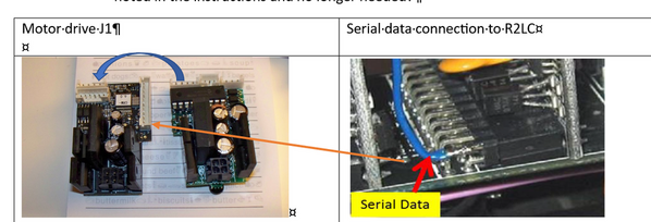
2. CCM Motor drive J1 and EOB 4 position connector: The ERR instructions note that in some installations, it is possible to move the former command unit to the CCM. It looks like I have this situation since the four-pin connector seems to match the CCM as shown by the blue arrow below on the left.

3. The 3 pin sensor connector at top of EOB- ignore, no longer needed.

4. Middle 3 pin connector on EOB: connect "Serial In" to Pin 1 on J4 of the CCM.  Do I need the serial out or chuff input connections for anything?

Other than this- looks like that is it for connections. Any land mines I am missing?

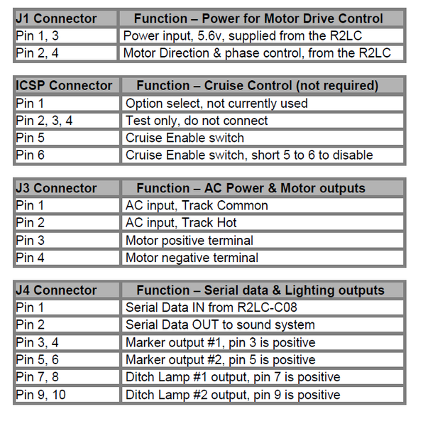
For reference, ERR and TAS EOB board pin connections.

Attachments

Images (5)
  • 102_8513
  • mceclip0
  • mceclip1
  • mceclip2
  • mceclip3
Original Post

Replies sorted oldest to newest

The serial data may be overloaded and not being seen by the CC-M.  The only connection necessary to the CC-M besides the black 4-pin power & motor and the 4-pin PWM connection would be the serial data from pin-24 of the R2LC.

Note that you have to then program the TMCC ID AND the engine type before it'll run correctly.

If that doesn't get it going, I'd suspect you may need to buffer the serial data from pin-24 of the R2LC.

Take the wire from the indicated pin...

Connect it here...

Attachments

Images (2)
  • mceclip0
  • mceclip1

Thanks, for the ideas. I will go through things again this afternoon and report back.  I will first do the TMCC ID and engine type setting again- can't hurt to do one more time. then will test Rail sounds disconnecting J4.  I " think" I am properly connected on the serial data from the R2LC but will check that too. 

If we have a buffer issue, this is the item we are talking about: Improved R2LC/R4LC Serial Data Buffer | O Gauge Railroading On Line Forum (ogaugerr.com)

Good news this morning. Per the excellent guidance, I found an "anomaly" (either me or the original install are guilty- your call) and made sure of the connection from pin 24 on the R2LC to the J4 pin 1 on the CCM. All works according to plan. This is a new CCM board and it appears the buffering is ok, but I plan to contact GRJ for future CYA needs.

I do have one odd thing going on.  I have a battery installed and when I shut down (zero volts to track and TMCC off), the sounds on the locomotive continue until I lift it off the "dead" track. Am I in the twilight zone or bermuda triangle here?

For anyone who finds this thread in the future, here is the pin out for the R2LC.

r2lcDWG pin out

Attachments

Images (1)
  • r2lcDWG pin out
@hokie71 posted:

I do have one odd thing going on.  I have a battery installed and when I shut down (zero volts to track and TMCC off), the sounds on the locomotive continue until I lift it off the "dead" track. Am I in the twilight zone or bermuda triangle here?

I suspect there's some kind of voltage leakage to the track, enough to fool the RS4 sensing circuit to thinking the track is still powered.  There was an issue with certain sound boards that they wouldn't shut down with power off and would kill the battery, but that was when they were even off the tracks.

When the power is shut off, measure the track voltage near the locomotive and see if there's some residual voltage there.

The rest of the story as Paul Harvey used to say......   

Nothing like working on a 15 + year old locomotive that has had an obvious history of modifications. At any rate, I decided to do a bit more disassembly and I found a broken / missing pin in the R2LC connector (blue arrow below), the famous pin 24 for serial data.  A past modification had made a solder connection to this pin on the back of the R2LC board and this is what I used to get my connection to the CCM board.  It appears there was no serial data going anywhere else due to this missing pin. Based on how the TAS EOB was originally wired, this missing pin has been missing for a while....  I did not realize why a wire was soldered there when I took out the TAS EOB.  This turned out to be an important connection. You can see the remains of the solder on the right side of the pin 24 connector in the picture.

Thanks again for the help to @Norton and @gunrunnerjohn - it appears my first CCM installation is complete (I hope).

missing pin a

Attachments

Images (1)
  • missing pin a

WOW, I've seen several of these installations, and none had the pin cut.  I never installed the drop-in EOB, so I never actually looked that closely at the instructions.

It's a low-class way to solve the problem, you have to break out the soldering iron if you need to remove the R2LC!

Just happen to be working on one of Dave’s engines now adding your chuff generator and that pin is cut.  I said WTH, why did Dave do that LOL

I usually can’t offer much to these discussions. I can follow instructions on how to do things but that’s about it. When I saw the mention of the cut pin. I remembered dealing with it recently. With no motherboards available I’m guessing there’s no elegant way to repair this other than a jumper wire. I guess at the time the EOB conversions were popular. No one was thinking down the road in 20 years of changing to something else.

The engine of mine that Gary has to add a chuff generator was one of the 2 I converted with a drop in board. Mainly to get 4 chuffs versus 1 and more usable speed steps. The other conversion was to get rid of the Odyssey lurch and to get 4 chuffs. I added a working back up light and changed the headlight to an LED to match it. What I thought was going to be a simple hook up wasn’t once I looked through the Forum archives. A shout out to Gunrunner John for a post with what was needed and how to do it.

Add Reply

Post

OGR Publishing, Inc., 1310 Eastside Centre Ct, Suite 6, Mountain Home, AR 72653
800-980-OGRR (6477)
www.ogaugerr.com

×
×
×
×
Link copied to your clipboard.
×
×