Hello All, this is my first post here and i hope i am posting this is the correct area.  If not then the Admin can move it.

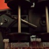
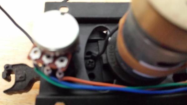
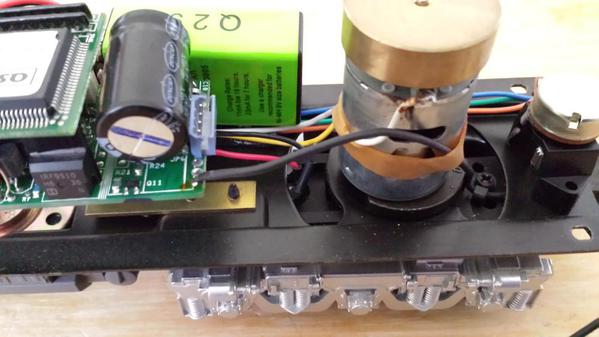
Anyway, i just purchased this UP Gas Turbine with Proto Sound One.  All is working well, but i am confused if anyone knows what the black wire is that is comming out of the back of the Diesel?  I also noticed that on the 2 other cars with the set, have some wires wrapped around the trucks both front and rear?  So can someone please tell me what these Mystery Wires are for.  Thanks Steve...

P.S. this is the set that was made in the late 90's

Last edited by mrnavy2
Original Post

Replies sorted oldest to newest

Hello mrnavy2, welcome to the Forum, in answer to your question the wire from the head end diesel is a plug that connects to the second unit above the coupler, since it's been a few years since I've run mine (its packed away) and if you are talking about the Coal Turbine which has 3 units, I believe the second unit also plugs into the third unit.  I'm in the process of building my layout and can't get to it at this time.  Also if your purchase is from the 90's it would be a good idea to replace the battery with a BCR, which looks like a 9 volt battery but holds a charge after the first minute you put power to the track.  Hope this helps.


Jack  

Steve, the first 2 units have smoke units in them and the third has tail lights among any other electronics each unit may have.  So when you  connect them all together all the functions built in will work.  Once you start reading all the postings on this form you will learn more every day, also you can search topics available to answer most questions you may have.  Although you have the Rail king version I have the Premier, which most likely both have the same electronics.  So plug them all together and have a fun time, and Happy Easter.


Jack    

Last edited by Dr. Jack
First I want to say Happy Easter to all. 2nd, I believe the wire I am talking about gets connected to wires from loco to car, then the third car for the electronic coupler. I was hoping it was for additional lights or for the diesel steam. Anyway here are the pictures that I took after I remove everything. Steve. 20150405_13280520150405_13283520150405_13291920150405_13583020150405_14080920150405_14084420150405_140924

Attachments

Images (7)
  • 20150405_132805
  • 20150405_132835
  • 20150405_132919
  • 20150405_135830
  • 20150405_140809
  • 20150405_140844
  • 20150405_140924

mrnavy2 -


Not to smart-off, and I am not, but you mentioned being new to this, and I'm not, so:


This loco is not a "diesel"; it is a gas turbine loco, and would be referred to as simply a "turbine", in short form. "Diesel" refers to the type of prime mover (engine) in the loco-

motive, not the looks of the loco. I have heard this before; just correcting. (Before I get

jumped on, these turbine locos did contain a small diesel engine inside, a few hundred HP, for moving around the yard and running auxiliary systems for which a 70,000 RPM or so jet engine was not appropriate or efficient).


Also, there is no "diesel steam" from any loco - steam locomotives exhaust steam (and smoke), and diesels (and gas turbines) exhaust only smoke. 


There were also -steam- turbine locos, but that's a whole other conversation.


None of that helps with your model, but it's all part of the Whacky World of Model

Railroading.

Last edited by D500

What is the product number?  This looks like a RK which is the O-27 version.  Normally the Lead unit would have a 4 wire tether coming out of the back.  This would plug into a receptacle (mounted on the truck on the next unit.  The back of that unit would have another tether coming out that would plug into the last unit if this was a 3 piece set.


I don't see any of that, but you do have a full PS-1 set in the lead.  For coupler you would only need one wire coming off the switch in the lead unit and the other wire for the coupler is just grounded to the chassis.


So if this is a very early model maybe a single wire was used.  But normally the rear unit had a directional light and you would need that wire too, which is why the tether was 4 wire for a PS-1. 


If you find the switch.  The center post goes to the PS-1 board at the edge.  one outer post goes to the forward coupler of the lead engine, and the other post get the wire that goes out the back to the trailing unit.


Happy Easter to you too.  G

G, yes it is a 027, 3 car set. I do not have the product number. Wish I did. I have the instructions but it does not show the product number either.  I did hear it was made in the late 90s. And it does have a single black wire without any clip, but the B unit has a small male plug and the other wires have no clips at all. .. Happy Easter to you also. Steve.

If you look at the rear of the circuit board you see a blue 4 pin plug.  That is for the couplers.  I don't see a switch on the side of the frame on this one.  Not sure if you have one on, or near the fuel tank under the chassis.


I do see one black wire solder near the blue connector.  Some models soldered vice using a connector.


If you look under the board at the blue connector you will see the pins labelled Coil ACG Coil ACG.  The ACG are chassis ac ground.  the Coils at the trigger.  Both fire together for PS-1, which is why you had a switch.  You could select which coupler you wanted to open.


Does the plug on the B unit have the same shape as the blue coupler plug?  It normally does, just black.


Any PS-1 loc instructions will tell you have to operate PS-1 engine.  A few tricks with the bell and whistle button to activate features.  G

Add Reply

Post

OGR Publishing, Inc., 1310 Eastside Centre Ct, Suite 6, Mountain Home, AR 72653
800-980-OGRR (6477)
www.ogaugerr.com

×
×
×
×
Link copied to your clipboard.
×
×