This may help.
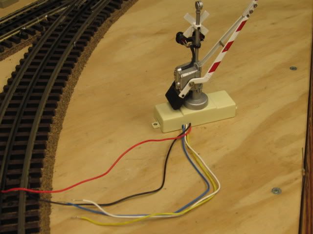
Crossing gate needs Power. Black and Red wire. Note connection to the outside rail and the center rail. Gate power could be any accessory power 12 to 18 volts AC.
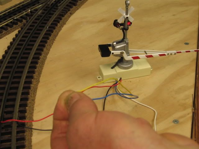
Touch the Blue and Yellow wires together. Gate goes down, and lights flash.
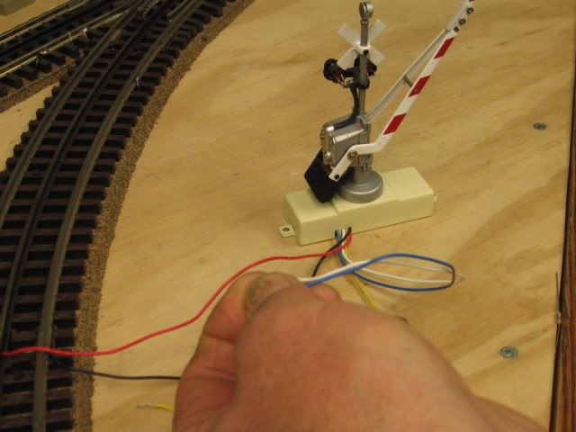
Touch the Blue and White wires together the gate goes up, lights off and stays up.
Note the relay pictured. There are (6) terminal on the left side, (2 sets of 3) top and bottom as the relay lays. You only need to use one of the sets.
One of the three terminals should be Common, connect to the Blue wire.
One of the terminals is NC (Normally Closed in the energized state) White wire.
And the last terminal is NO (Normally Open in the energized state) Yellow wire.
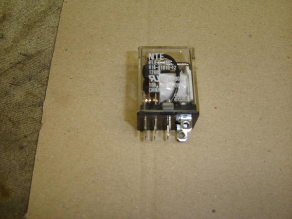
To operate the relay. (2) flat horizontal terminal that power the relay coil. Right two terminal in the picture.
I would prefer using an AC relay. Accessory common and Track common are one in the same.
Apply Track Power or Accessory Power to one of the two flat terminals of the relay.
Apply Track Common to the other flat terminal of the relay. Note that this wire is from an isolate, (outside) rail section. When a wheel/axle set applies common to this isolate rail section, the gate should operate via the energized relay.
Added note: The length of the isolate rail section should be long enough to accommodate both trucks of a car, to keep the relay engaged, gate down, for the length of the train.


