
@bmoran4 posted:

Generally speaking, most Lionel documentation recommendations are around one single common ground circuit.

This is entirely true. With the advent of DCS, and recommendations in Barry B's Bible, we got into further complexity in wiring, moving a bit away from the buss and more into star and home-run.

Last edited by Bruce Brown
@Bruce Brown posted:

This is entirely true. With the advent of DCS, and recommendations in Barry B's Bible, we got into further complexity in wiring, moving a bit away from the buss and more into star and home-run.

I think I'm using star/home run for the power lines, and the bus line for the common/ground only.

Last edited by Arnold D. Cribari

Great advice, Bruce.

Thanks to all you guys, I now have the information and knowledge I need to re-wire my layout. I have also bought the supplies I need for this project, including a good crimping tool that I just bought from Lowes. I also have fork/spade lugs, the terminal blocks and screws to mount the terminal blocks and TIU on a plywood board.

I will definitely replace the copper strips with the terminal blocks, and will color code the wiring, after which I will decide whether to keep my current feeder wires or replace them.

Concerning timing, part of me wants to get started immediately, and part of me wants to wait till I get a couple of locomotives back that are being repaired. Also, I know that once I disconnect the wires from the copper strips, my layout will down for a while, but I'm not sure how long.

I will give updates periodically.

Yes, we're getting close to Christmas. I am delaying any work on the layout that might make it 'dead' when kids and other guests visit for the holidays.

So, does it follow that if I simply connected wires between a U Post for each of my transformers (two Z4000 and two ZW), and all transformers are otherwise phased, that all ground wires can be connected to one common ground bus wire without any problems?

As others have answered Yes to this, I believe it requires clarification as long as that one common ground bus wire is sized large enough to carry the return of potentially four transformers. This is where my previous comment on think of the weakest link came in. If you continue to use the TB with the 18 wire between the terminals as you string these together the next TB sees increasing additive current. These TBs towards the end of the string could eventually see excessive current. Therefore, using the current TB with 18 wire would benefit from being returned to individual U terminal on the transformer.  Arnold hope this helps.

Arnold here is a visual that might help, assuming the transformers have been phased together.

This would be an acceptable buss wiring scheme

8FC5E663-6073-4E51-B44B-1D6B4B16A48D

This would not be as the weak link is the 18 TB jumper in TB 3 or 4 as the currents start to add up and potentially exceed the carrying capacity.

6EEBAEAF-D1F3-45C3-8419-C6A60A0010AE

This would be ok also going back to the same transformer as the hot.

7A6C3384-8843-4551-AA50-8D97F14E8735

Attachments

Images (4)
  • 8FC5E663-6073-4E51-B44B-1D6B4B16A48D
  • 6EEBAEAF-D1F3-45C3-8419-C6A60A0010AE
  • 55E626B0-2CBE-4548-92B5-94C05DD48F4A
  • 7A6C3384-8843-4551-AA50-8D97F14E8735

Arnold, I give you credit for rewiring your layout. Not an easy task. I kept mine pretty simple. I ran a buss around the layout, and have drops wired into the buss. I used neutral bars (AKA ground bars) to make the connections. I tinned the ends of the wires before I terminated them. I got the idea from Alan Arnold. I use DCS and have a signal strength of 10 at all points on the layout.

Andy


Attachments

Images (2)
  • mceclip0
  • mceclip1

For those considering re-wiring an existing layout, the hardest for me was all the crawling I had to do on the basement floor.

My layout is 48 to 50 inches off the floor, which is fairly high and should make the re-wiring easier. Nonetheless, it was still difficult for me.

The good news is I think I'm done with most of this crawling on the floor. What a relief!

While doing all the crawling, I had a funny thought that provided me with some comic relief:  "I'm the crawling king snake, and I rule my den." That is a line of lyrics from one of my least favorite Doors' songs: Crawling King Snake. That song appeared on the 2nd side of their Waiting for the Sun album.

The lead singer of The Doors, Jim Morrison, identified with snakes and other reptiles and often wore leather pants during concerts. He would also make primal screams during songs that sometimes had a reptilian quality. He was one strange dude but, IMO, had a great voice as a lead singer for a rock and roll band.

I tried to sing like him as a teenager, including the primal screams jumping an octave at the end of the song like he did in Light My Fire, and ruined whatever little voice I had.

LOL, Arnold

Today, I finished installing the hot wires for the 2 main lines. The primary hot wires are long 14 gauge stranded red insulated wires. Each one runs from the red or hot side of the MTH Terminal Block (MTB) for the particular main line loop (I have an MTB for the outer loop and another MTB for the inner loop). The other end of each primary hot  is connected to a short 16 gauge solid insulated drop wire from the lock-on.

The only exceptions are at the far left side and far right side of the outer loop main line of my 35 to 40 foot layout. There, I have a terminal strip at each end (with a bare 18 gauge wire threaded through the lower row of screws) to service the 3 or 4  hot/power drop wires from the lock-ons in that vicinity.. A primary hot wire (long 14 gauge stranded red) with a fork lug at the end is attached to the 1st screw on the lower row. The short hot drop wires are attached to the upper row of screws in the terminal strip.

Prior to seeing Rich's wiring diagrams that he recently posted, I had made a rough diagram showing the common bus wire and each terminal strip along it. The next step for me is to refine my diagram incorporating Rich's ideas.

Hopefully, tomorrow I will begin installing the common bus wire tomorrow with the terminal strips for it. Arnold

I am now about half way through installing the ground bus wire, including the terminal strips.

Next step is for me to connect all of the ground drop wires from the lock-ons to the terminal strips along the ground bus wire.

I have a question. I think I know the answer but am not 100% sure. I have my MTH Terminal Blocks (one for the inner main loop and one for the outer main loop) at the mid-point of my long and narrow layout and in front of my transformers. Can I simply run a short 14 gauge stranded and insulated wire from the black ground main terminal of each MTH Terminal block to a screw on a nearby terminal strip?

Arnold

Arnold I’m having trouble visualizing your wiring layout with the MTH TB placement. Is the MTH TB being supplied from your transformers? And than is the MTH TB the supply for the ground bus/terminal strip loop?

Yes, the MTH TB red post for the outer loop is getting power from the right Z4000 throttle (A terminal) with DCS, and the MTH TB red post for the inner loop is getting power from the left Z4000 throttle (D terminal) with DCS.

The black post for each MTH TB has a wire that is connected to a nearby terminal strip for the ground bus wire.

What do you think of this?

I'm confused as to why you're using a ground bus wire and terminal strips for this setup.

Wouldn't it be easier to just run a black wire from the black posts on the rear of your Z-4K (possibly the B and C terminals) to the respective black posts on each of your MTB's and then just run a paired, stranded wire from each post on the MTB to each power drop or whatever you're powering ? 

@SteveH posted:

Arnold is something like this what you're thinking aobut?

Star Ground

Steve, your diagram essentially shows what I am doing with my ground bar wire under the middle of my layout near my transformers and two MTH terminal blocks.

Since my layout is fairly long, about 35 to 40 feet, the ground bar wire runs the entire length of it and has about 7 or 8  terminal strips spaced 10 to 12 feet apart, which connected to the 14 gauge stranded ground bar wire and the 16 gauge solid ground drop wires from the lock-ons.

@Richie C. posted:

I'm confused as to why you're using a ground bus wire and terminal strips for this setup.

Wouldn't it be easier to just run a black wire from the black posts on the rear of your Z-4K (possibly the B and C terminals) to the respective black posts on each of your MTB's and then just run a paired, stranded wire from each post on the MTB to each power drop or whatever you're powering ?

Ritchie, thanks for your input.

I used the ground bus wire and terminal strips to reduce the length and amount of wires under my layout and near my transformers.

Your idea of using paired wire would also reduce the number of wires under the layout but, if I understand your approach correctly, I would need a lot more MTH Terminal Blocks (MTH TBs) than the two 12 post MTB TBs that I currently have. Also, I have a lot of lock-ons (35) on my 40 foot layout with 2 main line loops with 4 reverse loops (one on each end) and 9 sidings. I believe if I did what you propose, I would have a lot more long wires under my layout than what I will have when I complete my re-wiring scheme.

Rich Wiemann, I misunderstood Richie C's diagram.

What I have is 14 gauge stranded insulated wire connecting a ground (U) post of each of the two Z4000 transformers to the main black ground post of the MTH Terminal Blocks. There is no 18 gauge wire between the transformers and MTH Terminal Blocks. Therefore, I don't think I have an overloading problem.

Steve, your diagram essentially shows what I am doing with my ground bar wire under the middle of my layout near my transformers and two MTH terminal blocks.

Since my layout is fairly long, about 35 to 40 feet, the ground bar wire runs the entire length of it and has about 7 or 8  terminal strips spaced 10 to 12 feet apart, which connected to the 14 gauge stranded ground bar wire and the 16 gauge solid ground drop wires from the lock-ons.

I think your scheme, Steve, would work well with a more square shaped layout where MTH Terminal Blocks would be in the center.

A few things about re-wiring in general.

Electrical tape often comes undone in a couple days. I'm going to use wire nuts to re-connect wires wherever I crimped and soldered wires together and applied electrical tape over the connection, which I can do fairly easily because I have plenty of slack in my wires.

Patience is a virtue when re-wiring a medium to large size layout. IMO, it is a big mistake to rush a re-wiiring project. I try my best to keep my wits about me and remain ruthlessly rational throughout the project.

It's a very good idea to make a diagram of the re-wiring you want to do. That was a great idea someone else shared on this thread.

Take your time to carefully label the wires so if any get disconnected, you know the correct way to re-connect them.

Don't give up if mistakes happen early on and/or the project seems to take forever. For me, the beginning was the hardest part. Later on, you get into a good routine and find that the project is moving along more quickly than it did at the beginning with much fewer mistakes.

Get good equipment like a good soldering gun. I recently spoke to a Forum member with a great layout who recommended a Weller Professional D 550. I got it and it works great; much more powerful than the prior soldering iron I was using.

Ritchie, thanks for your input.

I used the ground bus wire and terminal strips to reduce the length and amount of wires under my layout and near my transformers.

Your idea of using paired wire would also reduce the number of wires under the layout but, if I understand your approach correctly, I would need a lot more MTH Terminal Blocks (MTH TBs) than the two 12 post MTB TBs that I currently have. Also, I have a lot of lock-ons (35) on my 40 foot layout with 2 main line loops with 4 reverse loops (one on each end) and 9 sidings. I believe if I did what you propose, I would have a lot more long wires under my layout than what I will have when I complete my re-wiring scheme.

You're right that it would use slightly more wire and longer runs but, to me, those are non-issues and more than offset by, a) only having to essentially make one connection from the MTB to the lock-on versus having to make two connections to the lock-on doing it your way - positive from the MTB to the lock-on and negative from the ground terminal strip to the lock-on and b) the ease of identifying which wire goes to which lock-on if you ever have an issue (the MTB comes with a nice pre-printed sheet so you can list which port goes to which connection) - your way you have to make up your own sheet (not a big deal), but then identify which two wires are going to each lock-on.   

If running out of ports on the 12 port MTB is an issue, you have two alternatives - one, you can string (daisy chain) together multiple 12 port MTB's by simply using one port on the first MTB to connect to the red and black posts on the next MTB or you can always go to the 24 port MTB's, which would give you 24 lock-on connections per handle/loop and, of course, you can always string more 12 or 24 port MRB's to those if you don't have enough.

Today, I awakened the Frankenstein monster and applied power to the largely, but not completely, rewired layout. Initially, the inner main loop ran fine, but not the outer main loop.

After 2 or 3 hours, I finally discovered one wire in the wrong position. When I corrected that, the outer loop also ran fine.

Next problem I need to solve is a Passing Siding that gets no power. I'm not sure, but I think the problem has to do with an Atlas Heavy Duty (HD) Switch not working, probably because of a short. They are on back order at Atlas so I see I'll need to hunt one down to replace the burnt out Atlas switch.

Problem with the passing siding is solved. On a relatively new piece of tubular O Gauge track, the insulation (between the center rail and the metal tie) was out of position so the metal tie was touching the rail. This is the 1st time this has happened in my 6 decades of model railroading. I repositioned the piece of insulation so it was where it's supposed to be.

It took me about 2 hours in the early morning hours (ideas for solving the problem came to me in the middle of the night) going through a process of elimination to diagnose the cause of the short in the passing siding.

I still have more to do in this re-wiring project, but I am now well over the hump, and am a lot more productive than when I started.

The crawling king snake (me) will be crawling on the basement floor a lot less, and even that is less of a PITA. LOL.

The rest of the re-wiring will be less tedious and burdensome, more satisfying (I feel like I've acquired more skills and better tools, including a high quality soldering gun), and even fun at times.

However, it still looks like a rat's nest of wires, just a substantially smaller rat's nest than before. LOL.

I've seen in person, and on this Forum thread, extraordinarily well organized wiring systems under masterfully built layouts, and wonder, at this point, if I will ever even approach that level of wiring.

Arnold….great that you fixed the siding issue. Yes, insulating piece issues are few and far between. Even with that track record I still use my multimeter to check between the hot and outside rail before installing.

Oh well, it may not be the neatest but if its functional that’s all that matters. All the trains care about is getting the hot to the center rail and the return back to the transformer. Just run them and look at the journey you made in less than two weeks.

All electrical problems can be resolved with two agendas😁

KISS…keep it stupid simple😃…translation: start with the simple stuff first…is it plugged in?; is it getting voltage or current? Should it be?


Second-Don’t let the smoke out…unless it’s supposed to smoke😁


glad you got your issue solved.

I’m still trying to squeeze 25 hours out of the day to get Time to work on my new Distribution panel…had both Grandchildren for the last 7 weekdays-so no alone time there

Then the weekend 😀Wife had projects-obviously they included me 👍

Then today-she drove over a deer two others just drove over right after someone else hit it…it ripped the wiring harness for the fuel gauge off —so naturally she assumed someone siphoned all her gas when she wasn’t looking😀

So, now the insurance is involved

And I wonder, why does God keep sending the Fates to take away my Time for non model railroading activities???


anyway…

@fastman posted:

Switch power  Depending on what light bulbs your using on the switches, you have an abundance of electrical supply. How many switches can you operate at once? Cheers Charlie

Charlie, I use 18 volt blue tinted LEDs in the 022 switches and 18 volt incandescent bulbs in the controllers. The 16 remote control 022 switches haved fixed voltage plugs and are independently powered by a ZW used exclusively for the 022 switches, so you are correct in saying I have an abundance of power for the switches. Arnold

The following is a puzzle for you electrical geniuses out there.

One of my goals for this re-wiring project was to eliminate a voltage drop and resulting slowdown/stop of my conventional locomotives in 1 spot and in 1 direction of my layout.

I share this here because I suspect I'm not alone and that many of us have, or had, similar voltage drops.

I will post a video of this later, but for the moment, will share some information about the voltage drop.

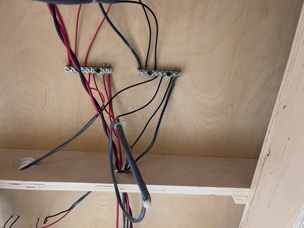
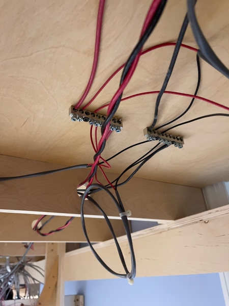
The location is in "My Little Town" at the far left side of my layout where 2 reverse loops (1 for the inner loop and 1 for the outer loop) converge, and where I have 4 crossing gates activated by insulated track sections.

The 4 crossing gates draw power directly from a ZW, not the track.

The reverse loops are independently powered by the throttles of a Z4000.

Now it gets interesting: the voltage drop only occurs on the reverse loop for the outer main loop, not the inner main loop, of the layout  and only in 1 direction. Specifically, it occurs when the locomotive is running counter-clockwise, not clock-wise, through that reverse loop, and on, and in the vicinity of, the 022 switch. All 022 switches are independently powered by a 2nd ZW.

To be even more specific, this morning I ran a Williams NW2 diesel at 8 volts, and the amps were 1.0 amp that dropped to .7 amp near that 022 switch. The diesel slowed down, almost stopped, but did not stop, at that switch.

There is no slow down when running an MTH Proto 2 or 3 on DCS.

What is your answer to this puzzle?

Arnold

Here is a video I took a couple of years ago demonstrating this voltage drop:

Some more info: there are 4 lock-ons with drop wires for power and ground on that reverse loop (1 just before the O22 switch, 1 just after that switch, and 2 before the insulated track sections). The power is drawn from the right throttle of a Z4000.

Attachments

Videos (1)
20181223_070649

Arnold, something to ponder: Even though the ZW is sending power to the crossing gates (hot side), since they're activated by the insulated rails, their common connection is through the track Common.  Gate activation increases the current flow which causes a slight voltage drop through the Track Common part of the wiring back to the Common ground bus connection.  Another matter is since the slow down only occurs in one direction, it may have something to do with the fact that only one outside rail has a hard connection to the Z-4000.  The other outside rail has the added resistance of the train wheels and axles.

All that aside, since the major slowdown evident in the video only appears to occur just before the switch where the train re-enters the mainline, there may be a couple of causes for this.  Depending on which outside rail is insulated and where the common feed is tied into this section of track, there may be poor conductivity between track sections on the Common powered outside rail.  If this Common powered outside rail is also the side which has the fibre insulating pin at the switch, then that last piece or two of track just before the switch only has it's Wired Common connection feeding in from one side and not the switch side.  Without more details on exactly how the Common wiring is configured, its difficult to know for sure how much any of this may be affecting the slow down.

If a locomotive has traction tires and they are all on the same side or has traction tires on the same side and the Common collector is only on one truck, that's also something to consider.

If you haven't already tried this, tightening the track around the Common connected outside rail pins, cleaning track, train and loco wheels may help.

Last edited by SteveH

My thought it was on the ground side as well, I don't think this is voltage drop caused by the hot side.  If you run a lighted car over the area, do you see the bulb dim (was thinking of this bc of the thought about traction tires). If the traction tire is on the ground rail that isn't insulated, it could cut down the return side significantly. You could try running several drops (ground) to the rail in the insulated section that is the return (non insulated) side and see if that helps (me I would find a way to attach them temporarily, like to each section of track in the insulated section, and see if it helps).

I would say maybe the transformers are out of phase (since they have to share a common ground for your setup to work ie one transformer powering the gates, the other the track), but it wouldn't be like this, I don't think they can be 'slightly out of phase' to cause a small power drop, it would be pretty evident, and not one way, either.

One other way would be in the insulated section to solder the rail joints on both common rails (within the section), to make sure that there is good flow on the negative rails, insulated and not and see if that helps, but making sure the connection is tight may be easier.

Steve and Bigkid, I believe what you say sounds like it has merit, though I don't fully understand all of it. Thank you for your input.

One reason I have not left no stone unturned in correcting this voltage drop is because for the train to slow down going through My Little Town is prototypical. A real train would also down down going through town.

Arnold- I just fixed the exact same problem on my upper loop. I only had one common wire connected in the rear of the loop. When I tested the voltage, it would go from say 10v with nothing on the track to 6v when a loco was drawing power. I added a second common drop on the front, and on the opposite outer rail from the rear connection. Problem solved. The current couldn't make it back to the transformer between the three switches. Good common connections are just as important as good hot connections. You would be amazed at the damage a loose neutral can do in building wiring.

This is a WbB conventional loco running at 8v. It would stall out before.

Bob

Attachments

Videos (1)
2021-10-24 21.54.49

To re-iterate, I'd suggest starting by improving the outside rail conductivity (lessen the resistance) at the track joints by either tightening the rail connection around the pin (pliers or crimpers) or as Bigkid mentioned by soldering the joints at the problem area.

If that doesn't improve operation, then identify where the Outside rail connection back to your Track Common is located in relation to the problem area.  If you do add another Common connection to the outside rail, you'd need to keep DCS track drop numbers and location recommendations in mind.

Last edited by SteveH

Continuity is King!

Big improvement:

I simply wired in series the ground terminals of 3 lock-ons around the curve and ending just beyond the switch as the train completes the reverse loop.

After having the trains down for 10 days or so while I re-wired the main lines, I am luxuriating in running trains again and - they have never run better thanks to all the outstanding advice I got on this thread.

Most of the re-wiring is done.

Next main project will be to get the sectional couch in the basement out of the house and then adding a 6 foot extension to the layout on the far left side where I will have a weathered custom made Lionel factory and a 2 stall engine house. That will give me 2 additional sidings to park trains. This layout expansion will be a very exciting and fun project and I will run a new Forum  thread about that project too. Arnold

Attachments

Videos (1)
20211105_153744

Early this morning I noticed 2 more lock-ons with no wires running to the ground clip, so I added drop wires from the ground clip and connected them to the Common/Ground bus under the table

Continuity was further improved. Below see an MTH Proto 2 Pennsy diesel hauling freight cars at perfect prototypically slow speed on DCS:

Arnold

Attachments

Videos (1)
20211107_071343

Early this morning I noticed 2 more lock-ons with no wires running to the ground clip, so I added drop wires from the ground clip ….

Continuity was further improved….


Arnold

Arnold sounds like your track pin connections have loosened up or has built up resistance internally to the track rails over the many years on your layout.  You may want to also check that the existing lock-ons are making good, tight and clean connection to the track rails. Removal of the lock-on and cleaning the outside rail connection points is straightforward.  You can also check the wire tightness under the holder clip. Additional lock-ons are certainly the easier and effective workaround for the pin issue.

Last edited by Rich Wiemann

Arnold sounds like your track pin connections have loosened up or has built up resistance internally to the track rails over the many years on your layout.  You may want to also check that the existing lock-ons are making good, tight and clean connection to the track rails. Removal of the lock-on and cleaning the outside rail connection points is straightforward.  You can also check the wire tightness under the holder clip. Additional lock-ons are certainly the easier and effective workaround for the pin issue.

Thanks, Rich, all of your ideas make perfect sense.

I'm having fun on a continuity crusade of sorts. LOL.

Incidentally, the real test is to run conventional or Proto 1 engines at slow to moderate speed. Before I added the lock-ons and drop wires for the ground, my Proto 2 and 3 engines on DCS were already running very evenly.

Arnold

Last edited by Arnold D. Cribari
Incidentally, the real test is to run conventional or Proto 1 engines at slow to moderate speed. Before I added the lock-ons and drop wires for the ground, my Proto 2 and 3 engines on DCS were already running very evenly.

Makes perfect sense, DCS engines have cruise and will maintain an even speed even with varying track power.

Thank you, Leroof.

I totally agree with you, John, about cruise or speed control. IMO, it is the most important change in modern locomotives (PS 2 and 3, LC+ and Legacy) vs. Postwar, enabling trains to run prototypically slow and smooth even on layouts with mediocre wiring and trackwork and significant voltage drops, like mine has had until very recently.

Last edited by Arnold D. Cribari

To hold drooping wires in place under the train tables, what do you folks think of using insulated staples?

Today, I bought a Cable Boss Staple Gun and one-half inch Cable Boss staples, which I may use tomorrow to position and hold in place certain wires underneath and on the bottom of the plywood tables

I used clamps to position and hold in place bunches of wires under the tables well above the basement floor.

Last edited by Arnold D. Cribari

I definitely like insulated cable staples for running Romex inside walls and ceilings.

For train layouts, I prefer Cable Clamps like these.  Attached with screws, it's easier to remove or add wires as circumstances may change in the future.  Often I will only run the screw through the back hole as I'm still running wire to make placement (and removal) easier.

cable clamps

For a layout already having scenery and buildings, not jarring everything by hammering in staples is also a plus.

Attachments

Images (1)
  • cable clamps
Last edited by SteveH
@SteveH posted:

I definitely like insulated cable staples for running Romex inside walls and ceilings.

For train layouts, I prefer Cable Clamps like these.  Attached with screws, it's easier to remove or add wires as circumstances may change in the future.  Often I will only run the screw through the back hole as I'm still running wire to make placement (and removal) easier.

cable clamps

For a layout already having scenery and buildings, not jarring everything by hammering in staples is also a plus.

I'm with Steve. I use these all the time. They are very versatile and wire pulls through them easily. Other than a Arrow T-25 staple gun to hold wires right where they come through the surface, I don't staple any wires under the layout.

Bob

Last edited by RSJB18

More update:

I did not like using the Cableboss staple gun and insulated staples because it was hard for me to use (hard for me to pull the trigger) and when I tested it, it worked, but it was very hard for me to remove the insulated staples from a plywood board. This might be a great product for someone who is 100% sure of where he wants his wires to be permanently fixed, but I'm not like that. I may have reasons to move wires in the future.

My new, but smaller, rat's nests appear in the photos below.

The pictures still show a mess, but it's a much, much smaller mess than before. Also, now, none of the wires dangle down to the basement floor.

I found the wire holder clamps and plastic 11 inch ties (to keep a bunch of wires together and tied to a table leg or piece of wood under the layout) were very useful.

Another reason for the mess is that I have not yet rewired the power wires to the 022 switch track plugs and the accessory wires, which I will do as an ongoing, and much less intense, project over the next couple of months. Arnold

20211103_152411

20211103_152343


20211103_152338


20211103_152332

Attachments

Images (4)
  • 20211103_152332
  • 20211103_152338
  • 20211103_152343
  • 20211103_152411

I've taken to using "plumber's tape" to keep wires neat and up against the bottom plywood layer of my layout.

Plumber's tape is not conventional "tape", but rather a semi-hard plastic tape about 1" wide and 1/8" thick that plumbers use to hold pipes in place. It's the modern version of the old copper strips with holes that plumbers use.

The tape comes in rolls of 100' or so. Basically, depending on how many wires I need to staple in place and how thick they are, I cut about a 3"- 4" long piece of the tape off the roll; place it over the wire(s) so that an equal amount of the tape extends out about 1" on either side of the wire(s); and then just staple the tape ends to the plywood with a heavy duty or electric stapler using 3/16" to 1/4" heavy duty staples.

The tape firmly holds the wire against the plywood and, to me anyway, is easier than using cable-type clamps. You can even bend the tape in the middle to form a little "loop" for the wire(s) to sit in.

It's available in white or gray on the big A or at most hardware/big box stores.


PLUMBER'S TAPE

Attachments

Images (1)
  • PLUMBER'S TAPE
Last edited by Richie C.

Add Reply

Post

OGR Publishing, Inc., 1310 Eastside Centre Ct, Suite 6, Mountain Home, AR 72653
800-980-OGRR (6477)
www.ogaugerr.com

×
×
×
×
Link copied to your clipboard.
×
×