
Arnold your continuing to make great progress…keep it going. I’m glad your working on a loop at a time and verifying your work as you completed it. That’s the easiest way to troubleshoot work that was just completed.

Yes, backing out the screws was necessary to loop around the easiest. The terminal block looks good and will serve you well. Is the tail you left long enough? How do you plan to daisy chain? Remember you have the mounting  screws at each end, and you will need to double up the wire under the first screw on the new block.

Question for you, how are you connecting the power lock on wire to the stranded wire running to you MTH block?

Keep making progress and the trains will be running in no time.

Zachariah, your club project is much bigger than mine. Thanks for your input, which is very helpful.

How did you connect your feeder wires to your main bus wire?

Arnold

Finally got around to getting another picture. As you can see there’s only a couple of feeders on this one but some have more. The barrier strips are strung out every 8-10’.

6B49F2A7-AEC7-4790-8BDD-D2198F7740E1

Attachments

Images (1)
  • 6B49F2A7-AEC7-4790-8BDD-D2198F7740E1

Arnold your continuing to make great progress…keep it going. I’m glad your working on a loop at a time and verifying your work as you completed it. That’s the easiest way to troubleshoot work that was just completed.

Yes, backing out the screws was necessary to loop around the easiest. The terminal block looks good and will serve you well. Is the tail you left long enough? How do you plan to daisy chain? Remember you have the mounting  screws at each end, and you will need to double up the wire under the first screw on the new block.

Question for you, how are you connecting the power lock on wire to the stranded wire running to you MTH block?

Keep making progress and the trains will be running in no time.

Rich,

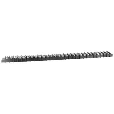
Here is my same photo of my terminal strip with the bare 18 gauge copper wire threaded through the bottom screws, illustrating what I say below:

20211027_233523

First scenario: my thought about daisy chaining, which may or may not work, is to connect the tail of the 18 gauge bare copper wire to a 14 gauge stranded copper wire that will run and be connected to a similar tail on the next terminal strip. I will make the connection by twisting,  crimping and soldering the bare 18 gauge tail wire to the 14 gauge stranded wire, then put black electrical tape over said connection. I would do the same thing with the tail of the bare wire at the other end of the terminal strip.

What do you think of the first scenario?

Second scenario: I could also cut off the tails and, using a fork lugs, attach the 14 gauge stranded wire to the 1st screw on the bottom (doubling it with the bare wire) or on the top of the terminal strip, and do the same thing at the other end if the terminal stripm

The 14 gauge stranded wire will start from the U or ground (common) post on the Z4000.

What do you think of the second scenario?

Concerning your question about how I will connect the power lock on 16 gauge solid drop wire to the 14 gauge power stranded wire, my plan was to make the connection the same way. That is, by twisting, crimping and soldering the wires together and covering the connection with black electrical tape. Do you think that will work?

By the way, to be clear, 3 or 4 of the top screws on the terminal strip will be connected to the ground 18 gauge solid drop wires from the lock-ons in the vicinity of the particular terminal strip. The series of daisy chained terminal strips connected to the ground 14 gauge stranded wire will serve as my ground bus wire running the entire length of my 35 to 40 foot layout.

Arnold

Attachments

Images (1)
  • 20211027_233523
Last edited by Arnold D. Cribari

Arnold think of the weakest link.

If I understand your concept the common terminal blocks (TB) will be daisy chain across your layout with the 18 solid on the TB and 14 stranded between each TB and lock on 16/18 solid drop with a return to the Z4000 by 14 stranded. Your weakest link being the smallest wire carrying the largest amount of current closest to the transformer. That would be true if you are connecting to one U terminal post. This would negate the need for using the 16 and 14 gauge wire.

Now if you split this daisy chain up by positioning strategically around and distributed this across the 4 U posts by running a 14 stranded from the U to your TB you would eliminate the weakest link of overheating your 18 wire.

I would personally just remove the short drop of 16 and replace with another 16 going directly to the TB and eliminate the connection with the 14. It will be cleaner and again less connections less potential problems.

This same method can be used for your hot connections also.

Hope this helps.

Last edited by Rich Wiemann

That can work, but electrical tape gets gooey and miserable over time and can fall off. Also, why go through the hassle of soldering upside down under a train layout?. Why not consider the Wago Lever Nuts discussed earlier?

@bmoran4 posted:

I enjoy using Wago lever lock connectors. They are infinitely better than suitcase connectors or wire nuts and less hassle to install than crimps. They are worth the extra costs hands down and are reusable! They also are good at joining varying sizes of wire (in this case AWG sizes 28 to 12 which is just perfect for our trains).

Here is are two assortments - one is the 222 style, the other 221 (40% smaller footprint):

https://www.amazon.com/Wago-22...rtment/dp/B01GVTVY12

https://www.amazon.com/Wago-22...018MGMFDI/ref=sr_1_3

Just be sure to get real Wago ones and not the off brand knock-off lever nuts as the knockoffs do not meet UL or other safety standards and are of inconsistent quality. That is not to say that one may not find that certain knockoffs are just fine for this low voltage purpose, but I can't justify taking the chance after getting burned.

@bmoran4 posted:

With the WAGO connectors, they actually act like mini terminal strips, but use surprisingly strong levers instead of screws to retain the wires. So yes, you need to cut/terminate your bus wire, but this is not a big deal at all. For illustrative purposes, the thick red wire could be the 14AWG BUS wire, the green could be 16AWG feeders:

In terms of command control signals or even just plain power delivery, the connectors themselves don't matter, but the quality of the electrical connection does matter, and that IS influenced by the connector type. Use of suitcase connectors are not typically used for connecting different gauge wires. Each gauge combination needs its own specific connector. The suitcase connectors actually sever the wire and can nick or even cut the copper conductor creating an intermittent hard to find wiring issue that can wreak havoc on command signals and power delivery. As such, I find suitcase connectors make a poor choice for quality electrical connections, especially compared to WAGO connectors that do not have these issues at all. Sure, some report success with suitcase connectors, but why invite the potential headache?

I used lever nuts to do my wiring, they were easy to use and allow for changes with no soldering and secure connections.

I used three position and five position models.

Lever Wire Nut 5 Conductor Combination

Lever Wire Nut 3 Conductor Combination

@bmoran4 posted:

That can work, but electrical tape gets gooey and miserable over time and can fall off. Also, why go through the hassle of soldering upside down under a train layout?. Why not consider the Wago Lever Nuts discussed earlier?

Just curious, how do you screw them to the underside of the layout? Do you use a Glue gun? I plan on using these going forward but don’t know how I’d connect them to the underside.

Nice to see you are making progress Arnold. A couple of comments;

I'm not sold on the 18 ga to act as buss wire for the TS, especially if you are going to daisy chain them. If you want to keep the 18 ga jumpers, then I would run separate feeds to each.

I like the WAGO connectors but don't overlook the humble wire nut. I've used them for years as an electrical contractor. Properly sized for the wire you are using, they provide solid connections with no need to tape over the splice. Look at the wire charts on the boxes until you find the proper size. You will quickly find soldering under the layout and overhead to be a giant PITA!

This is a chart for Ideal WN's.

https://elechut.com/wp-content/uploads/2018/04/wire-nut-color-code-nuts-fitted-vision-like-php-attachmentid-d-1.jpg

Properly securing stranded wire under a screw can be problematic. I would recommend forked crimps for all terminations........however....... I'm going to share an electrician's secret (so don't tell anyone) . Normally the wire strands are twisted clockwise, when compressed under the screw they will open up. Twist the wire in a counter clockwise direction instead, and when compressed, the strands will remain tightly twisted. Try it, you will be amazed.

I've soldered all of my track drops with a 40 watt pencil iron. I have 027 tubular track and it works fine. I usually place the wire at the base of the side of the rail where it forms the bottom flange. Clean the track well where you want to connect the wire and apply some soldering flux paste. Heat the wire and track with the iron and apply the solder until it flows nicely over the connection. The wire will need to be held securely until the joint cools and the solder hardens. I use a rosin-core solder as well.

2021-10-24 21.36.452021-10-24 21.36.492021-10-24 21.36.54

Keep us posted on your progress.

Bob

Attachments

Images (3)
  • 2021-10-24 21.36.45
  • 2021-10-24 21.36.49
  • 2021-10-24 21.36.54

For connecting wires, is twisting, crimping, soldering and then black electrical tape over the connection a good way to do it?

I realize this may be a belt and suspenders approach that may be overkill. Arnold

No, no, not a good way to do it. Bob RSJB18 and @bmoran4 are giving you good advice not use black electrical tape and, if you are only connecting two 14-18 gauge wires, using a spring wire nut (I like orange, but gray is good for smaller wire diameters). The lever nuts (suggested by GRJ, for example) or use of terminal strips with crimp spade terminals are great choices for terminating large numbers of wires. You should only be needing a soldering tool just to connect the wire to the track.

Last edited by Bruce Brown

Add Reply

Post

OGR Publishing, Inc., 1310 Eastside Centre Ct, Suite 6, Mountain Home, AR 72653
800-980-OGRR (6477)
www.ogaugerr.com

×
×
×
×
Link copied to your clipboard.
×
×