Hi All,

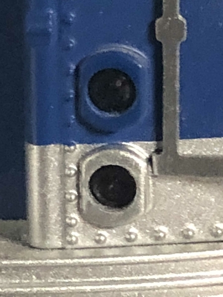
I'm about to swap all my NYC Subway cars over to LED's. probably about forty six car sets. I'd like to add head and tail lights to the last cars. The housings are there already. Only the LED's would have to be added. That's where my dilemma comes in.

If you not familiar with these sets, after start up with the DCS remote, the headlights and sound come on. If you hit the direction button, the tail lights come on and the train would back up if the speed roller was used. I'm looking for a circuit that would do the same in the last car, switch the lights when changing directions. I'm told it can be done in DCC by using a decoder, but I sure don't want to give up DCS.

Is there another way, maybe a circuit using an RF signal? The initial signal would come from the board lighting up the head and tail lights. Thanks for your help.

Brian

Housings

IMG_3482

Attachments

Images (2)
  • Housings
  • IMG_3482
Videos (1)
Video
Last edited by Rich Melvin
Original Post

Replies sorted oldest to newest

Thanks for the reply, are you still working on it, i noticed the last reply in that discussion was 9/30. Another thought I saw you mention four channels, Ideally I'd like to put the engine in the third or forth position because of the engine cover. Having the head and tail lights work the the lead and last car change switch, and the engine in the middle would be awesome.

Yep, I have prototypes, and most everything is working.  I'm just trying to get a ton of projects done, and some of them are slipping. I still have some work to do on the transmitter microprocessor code, I have a couple of glitches that I'm trying to sort out.

I'm also working on a Universal Sound Board that  offers both wireless and wired capability to trigger multiple sound files.  The sounds can be of any length from seconds to days, and they're user configurable using and SD-card.  I have the boards built, I just have to do the documentation and packaging.  So many projects... so little time!

Here's the production version of the sound board.

Attachments

Images (1)
  • mceclip0
@MCD4x4 posted:

Thanks for the reply, are you still working on it, i noticed the last reply in that discussion was 9/30. Another thought I saw you mention four channels, Ideally I'd like to put the engine in the third or forth position because of the engine cover. Having the head and tail lights work the the lead and last car change switch, and the engine in the middle would be awesome.

I'm sure I'll feel foolish for asking, but what do you mean by "engine cover"... i.e., reason you want the powered car in the middle of the consist.

Having the lead and last car change when switching direction should not be a problem with GRJ's design.  Each end car would have its own receiver board; both boards would listen to a single transmitter board in the middle-positioned powered car.  Only difference would be the headlights and tail-lights would be in swapped positions in the receivers.

Last edited by stan2004

Little by little John.  I got the rest of my switches in, and I'm soldering leads to the group on the liftgate so I can get that section nailed down.  That's kinda the anchor for a lot of the track, so that has to be right first.

It's real busy right here, and these have to be right to line up with all the rest of the track.  Any adjustments need to be made before I can move on.

Attachments

Images (1)
  • mceclip0
@stan2004 posted:

I'm sure I'll feel foolish for asking, but what do you mean by "engine cover"... i.e  reason you want the powered car in the middle of the consist  

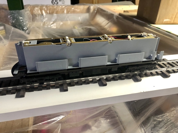
The MTH NYC Subways have a shell, or a cover over the motors to keep looking through the windows presentable. When the train is coming into the station, or leaving your vantage point, the first or the last two cars would look better seeing the interior, the seats etc.  so if the engine were moved to the third or forth position in a six car consist, ya really wouldn’t notice it. BBFE2BFC-0DA0-4728-9630-CE31C67CCA373C1BFEAB-73C8-4D1D-8BA0-94D426E4E73C

Attachments

Images (2)
  • BBFE2BFC-0DA0-4728-9630-CE31C67CCA37
  • 3C1BFEAB-73C8-4D1D-8BA0-94D426E4E73C
@MCD4x4 posted:

The MTH NYC Subways have a shell, or a cover over the motors to keep looking through the windows presentable. When the train is coming into the station, or leaving your vantage point, the first or the last two cars would look better seeing the interior, the seats etc.  so if the engine were moved to the third or forth position in a six car consist, ya really wouldn’t notice it.

Print out some passenger figures and glue them to the inner partition.

So for the record, I offer the following summary of various methods that have been discussed on OGR for directional lighting on subways.

Method 1.  Daisy-chained tether from the powered car to/thru intermediate cars and terminating at the end car(s).  If done with a wired tether, the power for the lights in the cars can come from the powered car.  This means the noisy pickup rollers can be removed all but the powered car.  Or the tethers could be wireless.  For example, some Lionel engines use a wireless infrared tether to talk between steam engine & tender.  I believe the Lionel Acela uses a wireless infrared tether to talk between cars.  However, I do not recall anyone actually implementing a daisy-chained tether (wired or wireless) for the matter at hand (end-car directional lighting in a subway consist).

Method 2.  Direction sensor on the end car. There is NO communication between the powered car and the end car(s).  In this case the end car is responsible for setting its own direction lights based on a sensor.  Ideas proposed in OGR threads have included an accelerometer sensor and a wheel-direction rotation detector.  The problem with this method is the direction lights only change when the consist starts moving.  Again, there has been discussion but I do not recall anyone actually implementing this.

Method 3.  Motor control board on the end car used just for lighting.  For conventional operation, the end car has an E-unit / reversing-unit.  It's "sole-purpose" in life is to provide direction information extracting the DIRECTION button track-power interruptions to alternate the lights.  The motor drive electronics is not used.  For command control, in the case of MTH subways, a PS2 or PS3 board is placed in the end car.  The PS2/3 board essentially "listens" to the same address as the powered car.  This seems like an expensive alternative but I seem to recall a relatively recent OGR thread where this was actually implemented.  MTH never offered a simple DCS accessory decoders for operating cars like ERR does for TMCC.

Method 4.  Wireless signal from powered car to end car(s).  This is GRJ's project presently under discussion.  In a previous OGR thread I showed a rudimentary version where the tail-light in the powered car turns on an RF transmitter whenever it is on.  A simple RF receiver in the end car detects this and turns on its tail-light.  This is/was very simple and inexpensive (maybe $5 total) but you could only have 1 subway consist in your train room!  That is, whenever in reverse, the powered car is rudely spraying RF energy every which way!  As discussed in the long thread about GRJ's project, the trick is to only send a short RF signal when the direction changes..and to only send that RF signal to the intended (addressed) end car.

@stan2004 posted:

So for the record, I offer the following summary of various methods that have been discussed on OGR for directional lighting on subways.

Method 1.  Daisy-chained tether from the powered car to/thru intermediate cars and terminating at the end car(s).

Method 2.  Direction sensor on the end car. There is NO communication between the powered car and the end car(s).  In this case the end car is responsible for setting its own direction lights based on a sensor.  Ideas proposed in OGR threads have included an accelerometer sensor and a wheel-direction rotation detector.  The problem with this method is the direction lights only change when the consist starts moving.  Again, there has been discussion but I do not recall anyone actually implementing this.

Method 3.  Motor control board on the end car used just for lighting. For command control, in the case of MTH subways, a PS2 or PS3 board is placed in the end car.

Method 4.  Wireless signal from powered car to end car(s).  This is GRJ's project presently under discussion.

but you could only have 1 subway consist in your train room!

Hi Stan, thanks for the reply.

For number one, I’m trying to stay away from the tether I’d possibly

for number two, the direction sensor is interesting, down side is the lights only working when moving. Not ideal.

For number three, a. PS2 or 3 board for this use would be big bucks, especially times forty.

For number four, I didn’t realize the channels would all be the same. The layout I am currently working on will easily accommodate thirteen subways running at once. hmm, so maybe this won’t work either.

Brian

@MCD4x4 posted:


...

For number four, I didn’t realize the channels would all be the same. The layout I am currently working on will easily accommodate thirteen subways running at once. hmm, so maybe this won’t work either.

Door number four is the way you want to go.  GRJ's method will support 13 subways at once.  In fact it would handle up to a million simultaneous subways if you are so fortunate to have such a ginormous train room!

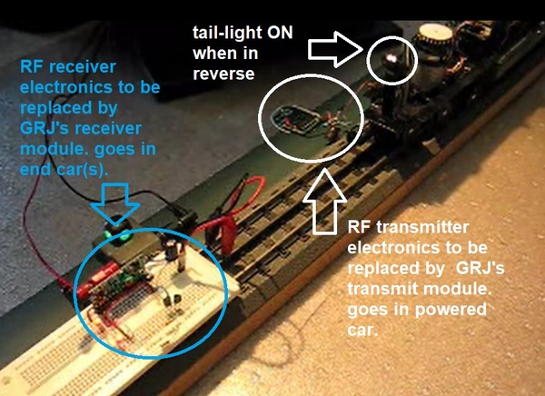
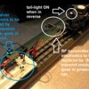
I was not clear.  I mentioned that years back I made a proof-of-concept video demo where a PS2 engine transmitted a simple ON/OFF RF signal whenever in reverse.  I can't find the original thread but here's a brief description from a 5 year old OGR thread on the topic.  Here's the video from that thread.  And here's a "new" annotated picture showing what's going on in the video.

subway hack

In the video, note the pair of white and pair of red LEDs in the receiver that toggle when the tail-light in the engine car turns on/off.

In the last 5 years (or so), inexpensive RF transmit and receive modules ($1) have become widely available on the likes of eBay that support a communications protocol allowing a million (or so) different addresses.  The trick is to only transmit for a brief fraction of a second when the transmitter has something to say...rather than transmitting whenever the powered car is in reverse.  So the powered car will only transmit a RF signal when the tail-light turns on...or when the tail-light turns off.  In other words only a brief transmission when the direction changes.

It appears that you are more than a Lookie-Lou!  Your application is a sliver of the capabilities of his "universal" one-size-fits-all project.  Obviously I can't speak to the pricing.  GRJ will certainly speak for himself, but I would be disappointed if the universal nature of the project would price it out of the ballpark for your specific application...times 40.

Attachments

Images (1)
  • subway hack
Videos (1)
ogr subway wireless backup light
Last edited by stan2004

I haven't gotten to pricing, and I don't know if I can justify a production run of these.  I think the transmitter module and the two single channel receiver modules would probably be the most in demand.  However, in order to offer assembled versions of these at a reasonable price, I have to run at least several hundred.  With three boards, we're talking about fronting thousands of dollars without any certainty of recouping my investment, never mind any profit on the venture.  Given that fact, I'm considering maybe I should try to re-spin the PCB for thru-hole and offer kits.  That is a much smaller outlay and I wouldn't be so nervous about fronting that kind of cash.

Yup.  I'm such a tight-wad and what I'll do to save a buck seriously clouds my judgment!  So don't listen to anything I have to say about what guys want and what they will pay for it! 

@MCD4x4 posted:

Hi John, would changing forward to reverse affect the train on the next track, make that ones light change?

1527 receiver

Perhaps a bit more of what is going on "under-the-hood" would make this more clear.  Each transmitter module (in the powered car) sends out RF commands with what amounts to a random digital address (about a million combinations).  On the $1 receiver module is a so-called "learn" button.  You press this button to put the receiver into "learn" mode.  Now the receiver is listening for a RF transmission.  You have the transmitter send a signal.  The receiver "learns" the address of the transmission and remembers it forever.  This is kind of like pressing the "pair" or WPS button to mate Bluetooth or Wi-Fi devices.  In your example of a middle-positioned powered car talking to 2 end cars you would have both end cars "learn" the address of the powered car.  You can have an unlimited number of receivers taught to listen to a specific powered car.  For example, you might want to command ALL the subway cars in a consist to turn their interior/cabin lights on and off together.  No problem!  Just put a receiver in each car and teach it to listen to the address of the powered car in the consist.  No other consist will pay attention to the goings-on of another consist!

Attachments

Images (1)
  • 1527 receiver
@stan2004 posted:

You can have an unlimited number of receivers taught to listen to a specific powered car.  For example, you might want to command ALL the subway cars in a consist to turn their interior/cabin lights on and off together.  No problem!  Just put a receiver in each car and teach it to listen to the address of the powered car in the consist.  No other consist will pay attention to the goings-on of another consist!

I understand that the head and tail lights become the signal for same to happen in the other two cars, but what would send the signal for the interior lights? This all sounds very promising. It seems like John has this pretty much figured out. The question is, are these going to be sold ready to plug in, or are they going to be sold as solder it yourself kits.

Brian

Add Reply

Post

OGR Publishing, Inc., 1310 Eastside Centre Ct, Suite 6, Mountain Home, AR 72653
800-980-OGRR (6477)
www.ogaugerr.com

×
×
×
×
Link copied to your clipboard.
×
×