


I own the  AC6000 #9876 but It says in the manual says It requires Lionel or Lionel-compatible O-42 or larger track curves  and this layout is  O36 curve and the layout is 8' x 13'  and it was built couple years ago and I would like to redo the tracks with O42 mth ReaTtrax on this track plan and not use  fastrack any more and only use ReaTtrax only on my layout

IMG_0821


IMG_0826

Attachments

Images (2)
  • IMG_0826
  • IMG_0821
Last edited by flemming
Original Post

Replies sorted oldest to newest

I didn't add the parts list because if you wanted to use the design I'd swap some of the 10" track for the longer 30" tracks and then post the parts list. So here's a version of that without the color-coded track to make thing easier to read. You should be able to download the jpg image and zoom in. Either way, you should consider swamping some of the 10" tracks for terminal tracks. Also, I'm curious, is there a reason you want to use RealTrax instead of FasTrack, especially if you already have some FasTrack?

Capture

Capture


Attachments

Images (2)
  • Capture
  • Capture
DoubleDAZ posted:

I didn't add the parts list because if you wanted to use the design I'd swap some of the 10" track for the longer 30" tracks and then post the parts list. So here's a version of that without the color-coded track to make thing easier to read. You should be able to download the jpg image and zoom in. Either way, you should consider swamping some of the 10" tracks for terminal tracks. Also, I'm curious, is there a reason you want to use RealTrax instead of FasTrack, especially if you already have some FasTrack?

Capture

Capture


Last edited by flemming
flemming posted:

because It says in the manual It requires Lionel or Lionel-compatible O-42 or larger for me to run the AC6000 #9876 and my  track  layout was made with O36 fastrack curve

Would you be interested in seeing what FasTrack O48 would look like if it will fit in the space? How about Atlas O45? Or do you prefer one of the tracks with faux roadbed built in?

Yes  DOUBLEDAZ  about the fastrack  O48  I have a question where the fire station is there is a tunnel there for some reason my locomotive stalls inside the tunnel any way to fix the problem ?? could you also show  what   it would like with the arch bridge on the layout if I stayed with the current layout and used O48 fastrack what would my current layout look like if i stayed with fastrack 


Last edited by flemming

I   came to realize  that replacing the layout with  mth  tracks  would be a pain   some one gave me an idea  using O48 curve fastack on my existing layout is there a way to fix the layout with the MTH arch bridge the same one in the in the photo i  would not know whereto start till I had a plan of my layout using O 48 fastrack

Last edited by flemming

Here's FasTrack O48 with an arch bridge someone put together. Photo 1 is color-coded to show the raised section. Photo 2 is bare track so you can hopefully see the track sizes. Photo 3 is a 3D view. The SCARM file has the color-coded track in it.

EDIT: Sorry, picked the wrong bridge file.

CaptureCapture1

Capture2

Attachments

Images (3)
  • Capture
  • Capture1
  • Capture2
Files (1)
Last edited by DoubleDAZ

This is what i have on the layout it's compatible with FasTrack  so I don't think I need 1 10"  MTH tracks

The Fully assembled and ready-to-install, M.T.H. RailKing RealTrax bridges are a great way to expand your O Gauge model railroad. Fully painted and compatible with any O Gauge track system, including Lionel FasTrack®, RealTrax bridges look great and are sturdy enough for even the heaviest of trains.

Last edited by flemming

Looking at the photo you posted, I can't tell how your tunnels are configured relative to the 2 crossovers, all I can see are the exits on the left, but not the entrances on the right. To be honest, I didn't really pay any attention to the photo, I just tried to reproduce the track design as close as possible using O48 curves. As you can see, that eliminated some of the straight tracks on the sides of the inside oval making it difficult to keep that building where it is in the center of the layout. It looks like you also have a spur to the right of the bridge and there is no longer room for that. Perhaps some more photos would help clarify things. Right now I can't see if you even have 2 crossovers.

Scarm has a learning curve. It is worth sticking to it. Each new trick mastered speeds you tremendously. I miss it (no windows to run it) What are the mountains made of? I'm wondering if "Dale's Booster" IN the tunnel is possible? ( Search "Booster Dale's legacy" GRJ, Stan & others continuing Dale M's work on a tmcc booster)

As Adriatic said, there is a learning curve to SCARM and I wouldn't expect you to pick it up the first day. However, you should be able to download the SCARM file and at least open it in SCARM. To download the file, you need to right-click on the filename and use the Save As option to save it on your computer and then you might have to change the file extension from txt to scarm.

Anyway, I've been trying to get close to what I think you layout looks like today, so here's what I've come up with. The pink/purple tracks are the grades to the bridge. The yellow bridge is at 5" elevation and as you can see, the grade up is 5.1% and the grade down is 3.7%. Unfortunately, that makes the inner oval fairly small and tight. In addition to the bridge, I added the tunnels and 2 buildings. The track centers are 4.5" from the edge of the decking and the centers of the tracks on the left in the tunnel are also 4.5" apart. I'm not sure how the fire station will fit in. The inner circle can't be any smaller it and the crossovers can't be moved to the right without increasing the 5.1% grade or lowering the bridge height. If you lower the bridge to only 3", then you can move things over by 2 of the 10" tracks and get the grade down to 3.9%. I didn't replace some of the 10" tracks with 30" tracks until you decide what you want to do with the bridge height, so the parts list is not accurate yet.

CaptureCapture2Capture3


Attachments

Images (3)
  • Capture
  • Capture2
  • Capture3
Files (1)
Last edited by DoubleDAZ

Outer loop. It stalls at the curve section marked  with a black dot on the layout right before the main big  mountain tunnel begins In this case my question how would i solve this problem would adding  wires from the outer tacks  an inner tracks help  keeping my locomotive from stalling  by adding power to the hole layout would like to redo the wiring  but don't know where to start that's why I am reaching out who know more  then I do about wiring a layout that is 8'x13' I use the legacy system  wold this MTH 24 Port Terminal Block / Strip  help like the one on the photo ??


MTH 50-1020 O 24 Port Terminal Block

IMG_0821

Attachments

Images (2)
  • IMG_0821
  • MTH 50-1020 O 24 Port Terminal Block
Last edited by flemming

Since the engine stalls in both direction when hitting that track, it sounds to me like you have a track in there that isn't getting power for some reason. Kind of hard to suggest something without being able to remove the tunnel and do some troubleshooting. You didn't say how you're feeding power from the transformer to the tracks. I use DCS, so I'd probably have at least 3 blocks with power runs.

Last edited by DoubleDAZ
nickaix posted:

Is it only the TMCC engine, or do other engines stall also? If you unplug the Command Base from the wall outlet (not just from the track), and run the TMCC engine in conventional, with a transformer, will it go through then?

Just want to eliminate the possibility of it being a TMCC signal issue.

both my legacy and tmcc  trainn stalls

DoubleDAZ posted:

Since the engine stalls in both direction when hitting that track, it sounds to me like you have a track in there that isn't getting power for some reason. Kind of hard to suggest something without being able to remove the tunnel and do some troubleshooting. You didn't say how you're feeding power from the transformer to the tracks. I use DCS, so I'd probably have at least 3 blocks with power runs.

flemming posted:
flemming posted:
DoubleDAZ posted:

Since the engine stalls in both direction when hitting that track, it sounds to me like you have a track in there that isn't getting power for some reason. Kind of hard to suggest something without being able to remove the tunnel and do some troubleshooting. You didn't say how you're feeding power from the transformer to the tracks. I use DCS, so I'd probably have at least 3 blocks with power runs.

I forgot to say my friend who made the tunnels for me used chicken wires

Ok, it may be signal issue, then. TMCC actually puts signal on the "earth" wire in your home wiring, so your home becomes a TMCC antenna. This is the signal the engine has to 'see' in order to operate. Too much metal between the house wiring and the train can interfere with the train's ability to pick up the signal. This might be what is happening in your chicken wire tunnel. You may be able to fix it by running a wire connected to earth (not to the track ground) into the tunnel, or connecting the chicken wire to earth, so the tunnel itself becomes part of the TMCC system. I'm sorry I can't give you more specifics because I have not had this problem myself, but I remember it being discussed quite a lot here at one time. (The closest I ever came is when we parked a certain large, die-cast engine in a certain spot that had another track underneath it. Trains on the lower track would lose TMCC. Rather than re-wiring, we just didn't park that engine there anymore!)

Search the forum for "TMCC" and "ground plane" to learn more.

That's assuming your other trains go thru that section alright. If nothing makes it through, it is probably a loss of power problem.

DoubleDAZ posted:
flemming posted:

I forgot to say my friend who made the tunnels for me used chicken wires


Based on your email, it seems it was a signal issue and you found a temporary solution. As I said, I know nothing about TMCC wiring, so I was completely in the dark.

both my tmcc and legacy stalls what i trying to do here is keep both trains from stalling what I am trying to say Is i would like to run all my trains with out any track issue or Interference on the layout

I would like to wire my layout the same way it shows in the picture  here hoping it would stop the stalling of both my tmcc and legacy engines can this setup be done??I have the Lionel TPC 400 and the Lionel Legacy hooked up to my current layout what gauge wire would i need if  went the that rout shown in the picture could I use the MTH 24 Port Terminal Block / Strip and could I wire my layout the same way shown In the picture showing wires going to section of tracks 


IMG_0875

Attachments

Images (1)
  • IMG_0875
Last edited by flemming

I don't run command and sound either; the electronics remind me of past work the mood has to be just right for me to enjoy them.

Interference is a case by case thing. I've worked on electronics that would refuse to operate correctly based on what outlet in a room was used, what type of hight voltage step down to local 440v was used, etc etc.. Just be confident very few folks don't track down their gremlin or have many (but a select few have put more than a fair share of effort to win... Cross the fingers; good luck )

The chicken wire is an issue,  gypsum content of wall material is another.  Either of the two can perform sheilding.

If I'm not mistaken the signal is run in the household ground. But regardless, one of the three is the carrier.

The answer is here somewhere if you search... but I usually try simple stuff by trial and error process of elimination and there's only two things to try and experiment with.

1. I'd start with the ground and try to simply run a wire along the "nice tunnel   ceiling to household ground. (Assuming it has a modern ground installation).  Use an outlet cover screw, that's should be ground. At the transformer is fine. If that didn't help, 2. a cheap extention cord would run the other two at once. But I'm pretty sure it's ground vs piggybacks on the two active lives.

How are you going to deal with the tunnel portals vs new track dia.? Tear it out, or only tear out what's needed.

It's always a shocker to me to a nice one like that get razed

Yes, you can definitely wire your layout like in the diagram you show. It is always good to have even power distribution. For a layout of your size, 16 gauge wire should be plenty good. You can use the MTH terminal block, but you don't have to. Wire nuts at the wire junctions work well enough.

I just want to make sure you are clear on the fact that that re-wiring the layout will probably not fix your TMCC / Legacy problem. TMCC is not picky about perfect layout wiring. (DCS is, but TMCC is not.) At my parents' we have a layout that is something like 17 x 30. It was built over the course of a decade, and the plan changed a few times. It was wired with whatever was lying around, or whatever was on sale. It's a rat's nest under there. And TMCC works just fine. What TMCC is picky about is interference. And that, I think, is why you are having trouble at the tunnel, because it is creating interference.

What Adriatic is suggesting, basically, is to get around the interference problem by putting a TMCC antenna inside the tunnel. Definitely try that. Get a single wire, and crimp one end under the screw in the center of the wall plate on an electric outlet. Make sure it is a 3-prong outlet. Run the other end thru the tunnel. The wire must not connect, electrically, to anything other than the screw at the wall outlet. This wire will serve as an antenna to get TMCC signal into the tunnel. See if that helps. (Try a couple outlets if the first one doesn't work, just in case you have non-standard wiring on some of them).

Unfortunately, Lionel's own documentation is not always super helpful on TMCC signal issues. The late Dale Manquen did us all a great favor by figuring this stuff out some years back.

flemming posted:

Outer loop. It stalls at the curve section marked  with a black dot on the layout right before the main big  mountain tunnel begins.

I still don't understand why the engines stop at a single track that is outside the tunnel, but then I don't know anything about TMCC. I would think that if the chicken wire is the problem, the engines would stop somewhere in the tunnel.

Be that as it may, you said in an email that you laid a piece of solid wire near that spot and the problem went away. That suggests the signal is the problem and adding multiple power drops should fix things. Here's a diagram using your design with 3 power blocks. If this were DCS, I'd have twice as many blocks, but 3 might be enough for TMCC. The large brown rectangle is the transformer and the smaller one is a terminal strip. Maybe 14 gauge from transformer to strip and 16 or 18 gauge from there to tracks?

Capture


Attachments

Images (1)
  • Capture


Did you try the conventional test? I assumed you had. If it stalls in conventional without a system hooked up, just a transformer, then you have dead track there.

Is it stopping inside the tunnels as you began with, outside the tunnel, or both, and what temp. solution was applied and what changed if anything....???

A weak connection could stop the signal also. Not 100% bad, but weak.  With a train on the problem track take a voltage reading from that track compared to elsewhere. I.e. a bad connection can flow low amp at full volts, but try to pull any amps and the voltage drops fast and hard; maybe stops flow altogether; a signal is even more sensitive to any weak connections.

Anyhow, I think you'll know soon enough if the track was the issue or if the signal is being blocked.

Mark those track sections where it stops now as you pull it out so later you can address it.

Adriatic posted:


Did you try the conventional test? I assumed you had. If it stalls in conventional without a system hooked up, just a transformer, then you have dead track there.

Is it stopping inside the tunnels as you began with, outside the tunnel, or both, and what temp. solution was applied and what changed if anything....???

A weak connection could stop the signal also. Not 100% bad, but weak.  With a train on the problem track take a voltage reading from that track compared to elsewhere. I.e. a bad connection can flow low amp at full volts, but try to pull any amps and the voltage drops fast and hard; maybe stops flow altogether; a signal is even more sensitive to any weak connections.

Anyhow, I think you'll know soon enough if the track was the issue or if the signal is being blocked.

Mark those track sections where it stops now as you pull it out so later you can address it.

It stall at the before the tunnel the I give it a shove it starts  up then stalls inside the tunnel

Last edited by flemming

Ok . Are there any power connections to bus, between these two points? 

You may have two issues. One section of bad track and signal loss in the tunnel. Run the "ground wire antenna" test see if it helps either spot. There is also another thing having to do with close parrallel track field isolation, but it's complicated. Start here if you want to hunt before you do anything.


Widows under the layout!  

  Actually, that happened to a cousins ho layout. A "pet" got away. He raised and sold scorpion, tarantula, widows, and rattle snakes.

  Once she spun a web he got her.  He sprayed something chemical, and something herbal at the doors and vents plus did a bleach washdown. Never did see the train run; the room, in between the washroom and lower level garage was sealed and off limits for the winter so a out a year total. But that could have been my Aunt & Uncle's call AND he was breeding ...? 

Call a pro. 

  If you can catch them without dying there's a market. They weren't cheap. But they love to get out and babies are oh so tiny. A bunch of tarantula would have sat better with me .

Adriatic posted:

Ok . Are there any power connections to bus, between these two points? 

You may have two issues. One section of bad track and signal loss in the tunnel. Run the "ground wire antenna" test see if it helps either spot. There is also another thing having to do with close parrallel track field isolation, but it's complicated. Start here if you want to hunt before you do anything.


Widows under the layout!  

  Actually, that happened to a cousins ho layout. A "pet" got away. He raised and sold scorpion, tarantula, widows, and rattle snakes.

  Once she spun a web he got her.  He sprayed something chemical, and something herbal at the doors and vents plus did a bleach washdown. Never did see the train run; the room, in between the washroom and lower level garage was sealed and off limits for the winter so a out a year total. But that could have been my Aunt & Uncle's call AND he was breeding ...? 

Call a pro. 

  If you can catch them without dying there's a market. They weren't cheap. But they love to get out and babies are oh so tiny. A bunch of tarantula would have sat better with me .

MTH bus wiring

If I did the way Dave's diagram  shows in the photo  can I use this MTH  block terminal when bus wiring my layout

Attachments

Images (1)
  • MTH bus wiring
Last edited by flemming
flemming posted:

If I did the way Dave's diagram  shows in the photo  can I use this MTH  block terminal when bus wiring my layout

That was just a basic idea and not intended to be an actual wiring diagram. But yes, the MTH terminal strips can be used, though there are many terminal strips on the market.

In any case, the diagram shows Block Wiring where main wires are run to 1 or more strategically located terminal strips and from there to individual connection points. Rather than run 3 long wires to each connection point, you run 1 long wire to the terminal strip and then shorter wires from there.

This photo shows Bus Wiring where 1 (or more) main wires are run around the track and then much shorter "drops" are connected to various points. In both examples, the idea is to separate the track into blocks and then run wires to a track in the middle of those blocks so power gets distributed fairly evenly.

Capture


Attachments

Images (1)
  • Capture

  A terminal block can help you keep things straight by labeling &/or a list, and it can speed connections along by avoiding some splice work, but it isn't a necessity. I use an older "universal" no-name terminal block and like to cut apart nylon euro terminal blocks for the screw set splice ability vs connections vs a crimp, etc.. (the best blocks have a wire gripping jaw inserts connected to the screw tip vs a screw tip alone. Without finesse the tip can mangle and cut wire if it gets turned too tight... they still work ok though)

flemming posted:
flemming posted:
DoubleDAZ posted:
flemming posted:

Outer loop. It stalls at the curve section marked  with a black dot on the layout right before the main big  mountain tunnel begins.

I still don't understand why the engines stop at a single track that is outside the tunnel, but then I don't know anything about TMCC. I would think that if the chicken wire is the problem, the engines would stop somewhere in the tunnel.

Be that as it may, you said in an email that you laid a piece of solid wire near that spot and the problem went away. That suggests the signal is the problem and adding multiple power drops should fix things. Here's a diagram using your design with 3 power blocks. If this were DCS, I'd have twice as many blocks, but 3 might be enough for TMCC. The large brown rectangle is the transformer and the smaller one is a terminal strip. Maybe 14 gauge from transformer to strip and 16 or 18 gauge from there to tracks?

Capture


Capture600

witch wiring diagram would be best to use with a terminal block  so I can get  started  as soon as I get rid of the black widow spiders they have made there home under my  train table to keep my Tmcc and Legacy engine from stalling on the layout

Last edited by flemming
flemming posted:

witch wiring diagram would be best to use with a terminal block  so I can get  started  as soon as I get rid of the black widow spiders they have made there home under my  train table

Like I said, I don't know anything about TMCC, so I'm going to have to let someone more knowledgeable comment. I don't know how many blocks this size layout should have, how many tracks in each block, etc. With DCS we tend to break things into blocks of 10'-13' lengths with 10 joints per block and the center tracks are isolated between blocks. We tend to use what we call Star Wiring, which is like my first example, though some use Bus Wiring too without problems. Maybe Adriatic will comment, but if no one responds, perhaps this is a question for the Electrical forum.

posted:

  A terminal block can help you keep things straight by labeling &/or a list, and it can speed connections along by avoiding some splice work, but it isn't a necessity. I use an older "universal" no-name terminal block and like to cut apart nylon euro terminal blocks for the screw set splice ability vs connections vs a crimp, etc.. (the best blocks have a wire gripping jaw inserts connected to the screw tip vs a screw tip alone. Without finesse the tip can mangle and cut wire if it gets turned too tight... they still work ok though)

Reaching out to Adriatic about the the two diagram witch wiring diagram would you use if you were in my place adding a terminal block one diagram has more wiring around the layout then the other diagram tying to take care of the stalling of both my TMCC and LEGACY Locomotives 

Last edited by flemming

I'm pretty sure Tmcc blocks are more about separation of of additional transformers/ bricks, than being there for signal reasons like with dts.    With Tmcc the feeds don't HAVE to be blocks, but can be drops instead. A drop off a bus still delivers power easier than rails alone can. Plain and simple, the more drops the less voltage drop, which is good. 

Actually. This wiring isn't really 'blocks' to me because it's from one source. It's a bus and drops to equalized isolated branches, but I roll with it

DC's likes equal branches I guess. Tmcc doesn't usually, if ever, suffer from it that I've heard of, so why not?   I often build with "if" in mind. 

IMO The only reason to differ would be focused more on conventional running alternative, where I like to add power drops in the curves because that's where they slow down and a good feed really helps. But Dave's second grouping actually looks pretty good for both dts & conventional both. The Tmcc is less concerned and just wants it's unbroken track path and signal airspace around it. 

I had the last tab open for for hours before using it, didn't see the question right away 

The more drops the better, but it may or may not help any signal issues. Those signal issues never have one single cut and dry or one size fits all solution. A solution is found beginning with a process of elimination.

I can't even take a stab at it  without the results from the conventional testing; I don't know your even getting power there on the spot outside the tunnel or in. 

Mostly when folks ask a series of questions it is in an attempt to piece together a puzzle. I didn't get enough answers to do that .

With more drops a terminal board would be nice. That's why they are made. But nice and necessary are two different things.

At this point I'd likely set up the new track loosely, and use the wire you have. If the problem occurs again with the new track, then you know track is not the issue and you can address the signal alone; before the track is perminantly set. 

Adriatic posted:

I had the last tab open for for hours before using it, didn't see the question right away 

The more drops the better, but it may or may not help any signal issues. Those signal issues never have one single cut and dry or one size fits all solution. A solution is found beginning with a process of elimination.

I can't even take a stab at it  without the results from the conventional testing; I don't know your even getting power there on the spot outside the tunnel or in. 

Mostly when folks ask a series of questions it is in an attempt to piece together a puzzle. I didn't get enough answers to do that .

With more drops a terminal board would be nice. That's why they are made. But nice and necessary are two different things.

At this point I'd likely set up the new track loosely, and use the wire you have. If the problem occurs again with the new track, then you know track is not the issue and you can address the signal alone; before the track is perminantly set. 

I talked to my friend Jose hes is the one who made the tunnels and did the art work he told me he want's to redo the tunnels and remove the chicken wire from the tunnels what do you think Adriatic he also notice signal drops in both the TMCC and LEGACY engines 

Last edited by flemming
Adriatic posted:

I'm pretty sure Tmcc blocks are more about separation of of additional transformers/ bricks, than being there for signal reasons like with dts.    With Tmcc the feeds don't HAVE to be blocks, but can be drops instead. A drop off a bus still delivers power easier than rails alone can. Plain and simple, the more drops the less voltage drop, which is good. 

Actually. This wiring isn't really 'blocks' to me because it's from one source. It's a bus and drops to equalized isolated branches, but I roll with it

DC's likes equal branches I guess. Tmcc doesn't usually, if ever, suffer from it that I've heard of, so why not?   I often build with "if" in mind. 

IMO The only reason to differ would be focused more on conventional running alternative, where I like to add power drops in the curves because that's where they slow down and a good feed really helps. But Dave's second grouping actually looks pretty good for both dts & conventional both. The Tmcc is less concerned and just wants it's unbroken track path and signal airspace around it. 

My use of the term "block" simply suggests that the design be divided into segments with individual power runs to each of those segments. It doesn't mean the segments have to be isolated like you'd do with conventional block control wiring.

DCS doesn't require equal "branches", but it does seem to work best when both wires from the transformer or terminal strip are the same length. This suggests not using bus wiring, but there are people who do and have no problems. DCS also likes the center rail to be isolated between "blocks".

Like I said, I don't know TMCC or the "airspace" around it, but I think you're suggesting that no matter how the layout is wired, he may still have signal issues in and near the tunnel because of the chicken wire used for the tunnel, it seems to be affecting that "airspace" you mentioned.

My 1st example was just to show how a terminal strips fits in. I divided the layout into several color-coded segments, but I didn't run lines from the terminal strip to each of those segments. My 2nd example was just to show how a single "bus" would run around the layout and have multiple drops to various points. I also color-coded segments, but only as an illustration.

From what I gather, TMCC doesn't been "blocks", so the colors can be ignored in both examples and the layout considered one big "block" with terminal runs or drops spread around the layout. I think Flemming is looking for specific than just general explanations of wiring schemes. If it were my layout, I'd use the first approach with a terminal strip located in the center of the layout and runs something like this. Again, the colors are just for illustration purposes. I would probably add another run for the spur.

Capture


Attachments

Images (1)
  • Capture
Last edited by DoubleDAZ
DoubleDAZ posted:
Adriatic posted:

I'm pretty sure Tmcc blocks are more about separation of of additional transformers/ bricks, than being there for signal reasons like with dts.    With Tmcc the feeds don't HAVE to be blocks, but can be drops instead. A drop off a bus still delivers power easier than rails alone can. Plain and simple, the more drops the less voltage drop, which is good. 

Actually. This wiring isn't really 'blocks' to me because it's from one source. It's a bus and drops to equalized isolated branches, but I roll with it

DC's likes equal branches I guess. Tmcc doesn't usually, if ever, suffer from it that I've heard of, so why not?   I often build with "if" in mind. 

IMO The only reason to differ would be focused more on conventional running alternative, where I like to add power drops in the curves because that's where they slow down and a good feed really helps. But Dave's second grouping actually looks pretty good for both dts & conventional both. The Tmcc is less concerned and just wants it's unbroken track path and signal airspace around it. 

My use of the term "block" simply suggests that the design be divided into segments with individual power runs to each of those segments. It doesn't mean the segments have to be isolated like you'd do with conventional block control wiring.

DCS doesn't require equal "branches", but it does seem to work best when both wires from the transformer or terminal strip are the same length. This suggests not using bus wiring, but there are people who do and have no problems. DCS also likes the center rail to be isolated between "blocks".

Like I said, I don't know TMCC or the "airspace" around it, but I think you're suggesting that no matter how the layout is wired, he may still have signal issues in and near the tunnel because of the chicken wire used for the tunnel, it seems to be affecting that "airspace" you mentioned.

My 1st example was just to show how a terminal strips fits in. I divided the layout into several color-coded segments, but I didn't run lines from the terminal strip to each of those segments. My 2nd example was just to show how a single "bus" would run around the layout and have multiple drops to various points. I also color-coded segments, but only as an illustration.

From what I gather, TMCC doesn't been "blocks", so the colors can be ignored in both examples and the layout considered one big "block" with terminal runs or drops spread around the layout. I think Flemming is looking for specific than just general explanations of wiring schemes. If it were my layout, I'd use the first approach with a terminal strip located in the center of the layout and runs something like this. Again, the colors are just for illustration purposes. I would probably add another run for the spur.

Capture


In this diagram wouldn't I use red and black wires  

DoubleDAZ posted:
flemming posted:

In this diagram wouldn't I use red and black wires  

Yes, each line would consist of red and black wires, I didn't see the need to draw both.

Thank you Dave. Now  all I have to do now is call the exsterminater to come and get rid of  the black widow spiders that are making there web under neath the train table they like hanging out there I want to get rid of them so I can start doing the wireing  with my helper and relocate the controls to the ouside of the layout and not have the controls  in the middle of the layout 

Last edited by flemming

Dave posted: "Like I said, I don't know TMCC or the "airspace" around it, but I think you're suggesting that no matter how the layout is wired, he may still have signal issues in and near the tunnel because of the chicken wire used for the tunnel, it seems to be affecting that "airspace" you mentioned."


Bingo! The term "airspace" was chosen because two tracks in close proximity could also be an issue. Being similar issues "airspace" was all I could come up with to quickly convey all of my thoughts. The chicken wire can block a signal, creating a sheilding over that track that the airborne signal can't penetrate. The section outside the tunnel is the big twist. Two areas may or may not be the same issue. The issue with one section could be lack of power flow or signal. One is definitely a signal issue, maybe both. Running in conventional rules out track issues, leaving just a bad signal to consider. "Blocks" does the trick but I've always felt there was a better, more precise term out there somewhere to be used. The buffer is the booster I mentioned fyi. Redoing the mountains? I was worried you may have to redo tunnel portals near curves for engine/car clearance anyhow. I couldn't really tell if it was an issue But I think the addition of the buffer or ground/signal wire somewhere under the chicken wire is worth a shot unless you just want a good excuse for doing some new mountain work too.

Last edited by Adriatic

I'm not trying to talk you out of using bus wiring. I've never had a large layout, so I've never done bus wiring. But, you kept asking about the terminal strip and I didn't see a practical way to use it with bus wiring. I did see some diagrams that looked something like the photo where the main wires would run to the terminal strip and bus wires would run from that with drops off them to the track. I honestly don't know which would be better, easier to maintain, etc. Heck, I don't even know where you plan to put your transformer. I was just trying to illustrate the differences and give you ideas. I had expected others to chime in and suggest improvements to any of the diagrams, but that hasn't happened.

Capture

Attachments

Images (1)
  • Capture
DoubleDAZ posted:

I'm not trying to talk you out of using bus wiring. I've never had a large layout, so I've never done bus wiring. But, you kept asking about the terminal strip and I didn't see a practical way to use it with bus wiring. I did see some diagrams that looked something like the photo where the main wires would run to the terminal strip and bus wires would run from that with drops off them to the track. I honestly don't know which would be better, easier to maintain, etc. Heck, I don't even know where you plan to put your transformer. I was just trying to illustrate the differences and give you ideas. I had expected others to chime in and suggest improvements to any of the diagrams, but that hasn't happened.

Capture

where the brown box is in the diagram  that looks like a transformer will Quick Splice Tap Wire Connectors work

Last edited by flemming
flemming posted:
where the brown box is in the diagram  that looks like a transformer 

The large brown box does represent a transformer while the smaller one in the middle represents a terminal strip. I don't know if you plan to put your control center there or not. I could have easily put it on one of the other sides, it was just easier in the software I use to put in there. I also did the color-coding without giving it serious consideration and I don't know if you have accessories that need power. Obviously the switch will need power, unless it's manual. And now that I know TMCC doesn't need "blocks" of any kind, the color-coding is not needed at all. One article I read said ideally every track would have a power drop, but that would be serious overkill. Adriatic said he wants to add drops on his curves because his trains slow down there. Now that I look at things, I kind of like the latest diagram because most electrical is along the edges, that means less crawling way under. That's why these diagrams are for illustration/discussion purposes only.

It looks great, but I don't like that type of connector. While stuffing the bus into the v-groove, wire strands often get cut. Each nicked or cut strand is a bad thing. It lowers the wire capability a wee bit.  Other folks love them. I've had many bad experiences with similar and avoid them till they are my only hope.

Search for WAGO connectors or lever type connectors, they can be reused and may even be cheaper. I think you'll like them if you want things simple and changeable without as much future cost/waste.

A regular, smaller "euro terminal block" would mount more like what's pictured but do a better job imo. Remember you can buy Euro's in long strips and cut what you need; 1 or 20. They do need small jumpers to connect the side by side terminals, the connections are individual, two screws for a single in &an out on one tiny section; next to another, next to another etc.

Nothing "wrong" with anything I've seen Dave. I didn't feel a need to echo you being right, plus if you had email contact, don't know what I missed    I was pleasantly surprised on that second one the DCS focus seemed so well balanced to the curves if conventional was used.  As I said, I'd likely wire to be DCS ready as well. As for the actual insulating of the center rails from each other, that could come later with a dremel disk's slice.

Adriatic, you only missed a note about laying some wire near the stall location that resolved the signal problem, but I believe he mentioned that in the thread later too. That's when I realized it probably was a track problem and more likely your "air space" problem with the chicken wire in the tunnel. And since it's a garage layout without many electrical outlets/wiring, that tunnel could be blocking the signal enough to affect that one track just outside.

As for echoing, I'm not an expert at wiring, so I kind of needed the confirmation to know I was on the right track with the diagrams.

Adriatic posted:

It looks great, but I don't like that type of connector. While stuffing the bus into the v-groove, wire strands often get cut. Each nicked or cut strand is a bad thing. It lowers the wire capability a wee bit.  Other folks love them. I've had many bad experiences with similar and avoid them till they are my only hope.

Search for WAGO connectors or lever type connectors, they can be reused and may even be cheaper. I think you'll like them if you want things simple and changeable without as much future cost/waste.

I'm asking because I don't know, but isn't the idea behind bus wiring to use a "single" wire for the bus and tap into it with the drops? The Wago connectors and euro-style terminal strips are dead-end style connectors where you strip the end of the wires and plug then into the connector. If you want to extend the "bus", you need to add another wire to get to the next connector. That means the bus is no longer a single wire, but a series of daisy chained wires. I suspect either method will work just fine, so it's probably just a personal preference and using the right size wires.

Capture


Attachments

Images (1)
  • Capture
rtr12 posted:

I don't know about the correct 'bus' terminology, but FWIW, I would consider the two examples in your picture to be identical in function. Nice drawings, BTW...still done in SCARM? (I finally broke down and purchased SCARM so I could view all your (and others) track plans posted around here.) 

Thanks and yes, the diagram was done in SCARM though it would have been easier in RR-Track.

As far as functionally goes, I suspect either type of connector and wiring scheme would work. However, doesn't breaking the "bus" wire into multiple segments reduce conductivity? Maybe not enough to affect operation, but still a reduction? I always thought the idea behind bus wiring was to use a single wire so the signal would be stronger over a longer distance.

FWIW, I believe you would have been able to open any file in the trial version of SCARM, you just wouldn't have been able to make changes if the track count was more than 100. Always happy to see someone support Mixy's efforts though and I'm sure he appreciates the support. Now you can convert your design to SCARM and maybe play with some expansion ideas.

Tommy, I don't know if Flemming has decided yet how high his bridge will be, he hasn't said how high it is now. If he uses a standard trestle set, I believe the height will be 5". That's the height I used in the design and that puts the grades (purple) at 5.1% upper and 3.7% for lower. If he lowers the height to 3", the grades change to 3.1% and 2.2% respectively. If he reduces the number of tracks in the grades, the percentages increase and he's limited on the upper by the crossing.

Capture


Attachments

Images (1)
  • Capture
That self posted! The idea of a bus is to move power in bulk to a more available location(s) with as little loss as possible. Usually that's more power than would be used by an individual component. In the end it simplifies installation and often saves some wire as well. Many wires vs few stands a better chance at creating or being influced by outside fields as well. Doesn't really apply here (yet ) A negative might be a stronger field in a fat wire effects a smaller wire easier because it often has a stronger field. Yes, even though insulated, and especially with signal transmissions, wire paths and crossings can interfere with each other. Usually it's a feed voltage breaking the signal up. 2" has been my magic distance with serial data and power runs that wanted to fight. You never know till a system's use is attempted. Shielded wire has a wrapping of foil that can help prevent interference. It's used regularly when a signal carrier is vulnerable to outside fields. There is a certain amount of resistance involved with every splice. But if done nicely, it's hardly readable. For our purposes, you may as well say none. So yes in theory no break in the bus is better, but that's overkill for general purpose low voltage wiring. I worry more about heat than anything. I run wire gauge in overkill to avoid it. I've seen too many closely gauged systems burn up the wiring when one gauge larger would likely have saved a whole system. (Especially automotive, and getting worse imo as companies try to eliminate any excess cost right down to tiny bits of slack that would be useful upon a repair in the area. I don't wire with profit in mind ) Our standards are set for operational parameters; I like to step it up to preventative. E.g. despite Lionels suggestions, I'd be prone to run 14g vs 16g. In fact, I run most of my buses in 12g; and if 10g was handy wouldn't shy from it either. My wiring should be the last of my worries even under a long term direct short. It won't likely melt insulation in the worst of situations. Each nick in a wire makes the gauge weaker. A broken strand as well. I've lost as much as 50% of a wire in suitcase connectors, so I don't use them often and pay close attention to detail when I do. Pressure has a HUGE impact on connectivity. A wedge fit can loose pressure again pretty easy. It may have more pressure than a sprung lever, but the sprung lever stands less chance of loosing it's pressure, and if it did due to wire deformation, by say ...over time, it could more likely and more easily be reseated imo. A screw terminal or solder is the "best", but I like the WAGO style for it's ease of use too.

Adriatic, good explanation. As I said, I was just commenting that "technically" there has to be a power loss, albeit minimal, using multiple wires for the bus.

Anyway, I don't know how the layout is currently wired. One photo shows the transformer in an access area in the center of the layout, presumably with power going from there to multiple points around the layout. I don't know if he's using FasTrack terminal track(s) or some other connection and what size wire. But, my concern is that none of this wiring discussion makes much difference if his stalling problem is not related to power distribution. He can move the transformer, rewire using block or bus wiring, use whichever connectors he wants and the signal will still be blocked. My guess is rebuilding the tunnel without the chicken wire will resolve the stalling issue.

I actually think he could simply:
- move the transformer to wherever he wants it
- put the MTH terminal strip where the transformer is now
- connect the current track wires to the terminal strip
- run the main wires from the transformer to the terminal strip

I'd still like to know how the layout is currently wired. If power is not the issue, then why rewire it just to relocate the transformer?

Fine points Dave. I placed moving the transformer so low on priority I more or less dismissed it. The terminal block would certainly save effort there.

I assumed with new curves going in the track issue would be cleared up on it's own, but looking at the pictures more ....(unavailable some days as Android is so hit and miss. E.g. Today I can't do anything but post, no likes, no quotes, no attachment tool, and no thumbnail views.. pictures MUST be in the text 90% of the time, likely no search as well considering the others issues. It may clear up later; but usually clears late Sunday night).... I can see the issue could be on straights and remain. That conventional test sure would help narrow it down and save a lot of unneeded speculation.

I guess we'll see what Flemming has to say after he's had time to digest all this.

Going from O36 curves to O48 curves will mean most track has to be moved, so rewiring is not a bad thing. I just don't want him to spend a lot of time/money on connectors, etc., if a complete rewire is not going to fix the stall issue anyway. From what I can tell, except for the stall, the layout works the way it's wired now, so why not take the easy route and just move things around a bit?

DoubleDAZ posted:
rtr12 posted:

I don't know about the correct 'bus' terminology, but FWIW, I would consider the two examples in your picture to be identical in function. Nice drawings, BTW...still done in SCARM? (I finally broke down and purchased SCARM so I could view all your (and others) track plans posted around here.) 

Thanks and yes, the diagram was done in SCARM though it would have been easier in RR-Track.

As far as functionally goes, I suspect either type of connector and wiring scheme would work. However, doesn't breaking the "bus" wire into multiple segments reduce conductivity? Maybe not enough to affect operation, but still a reduction? I always thought the idea behind bus wiring was to use a single wire so the signal would be stronger over a longer distance.

FWIW, I believe you would have been able to open any file in the trial version of SCARM, you just wouldn't have been able to make changes if the track count was more than 100. Always happy to see someone support Mixy's efforts though and I'm sure he appreciates the support. Now you can convert your design to SCARM and maybe play with some expansion ideas.

Well at least you know what's easier in what program.  I still struggle with both, although I haven't been into either one for a while now. Last RRtrack session it crashed on me and I just closed it down and quit.  

I suppose you have a point about the 'bus' being continuous, I'm really not sure of the exact differences between the two methods? Maybe I'll look around a bit, I am now a bit curious about this. Probably way to technical for me, EE type stuff, but I'll see anyway...

I got SCARM somewhat for viewing others plans posted here, some for fiddling around with it, and also for support of a good product. I don't recall ever crashing SCARM either? I would hate to see Mixy lose interest and stop developing the program. And I went back later and got the train running thingie... 

Edit: I think my questions have been answered above, in Adriatic's post. I should have turned the page before replying...

Last edited by rtr12
rtr12 posted:

Well at least you know what's easier in what program.  I still struggle with both, although I haven't been into either one for a while now. Last RRtrack session it crashed on me and I just closed it down and quit.  

I think I crashed SCARM once when I was beta testing the simulator way back when, but the RRT crashes are really irritating. You won't believe how much I struggle using RRT yesterday because I've gotten so used to SCARM. I find myself trying to do things the SCARM way and get all sorts or weirdness. Both are definitely programs you need to use often to stay proficient.

Hi Guys, been following this discussion for a few days. All are very good suggestions submitted by you and presented to the readers in a down to earth manner that is easily understood.  I need that!!!  I do have one item I'd like to add to this post.  You guys have covered very well getting wiring from the xformer to a terminal strip for one type of layout and also bus wires to take power around an layout.  You discussed items(methods) to join bus wires to track feeder wires. Now can someone chime in to offer ideas for some good methods to connect my track red & black feeder wires to my track.  OK guys, the best method or ideas to join feed wires to my GG track.  Convenience, ease of installing, is important and I had rather spend a couple of bucks to save a couple of hours.  I need to go  thru my plyboard and homosote(sp) top.   Hey you guys know what I mean.

My best regards

Tommy

First, I am not all that familiar with Gargraves track (I use Atlas).

However, I believe some folks use this type of quick connect and stick them in the slots in the bottom of the rails.  These are just a couple of pics I found, one insulated and one non-insulated. You would need to get the proper size to fit the wire size you are using. Using the proper crimper is highly recommended if you are going to crimp as your only method of fastening. Many people using these connectors crimp and then solder the wires for best possible connections (crimper is not as important using this method).

Gargraves may even have some type of connector like this that they make for this purpose? I think they do have some type of stuff that slips in the bottom rail opening. Others that use the track can probably explain further.

The only other method I know of for that type of track is soldering directly to the track. This is the preferred method for some folks around here. Hope that helps you a little.

.250 Wide Spade Crimp Connector

 I'm sure GG offers an easy solution. 
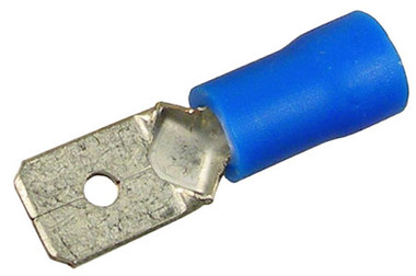
  The blades are ok, on some track needed because it won't take solder. They can take some effort to seat.  I've had to whack and pry some track webs open a bit with chisel, screwdriver, or knife and a small hammer.
Rails have 3 main parts, a "foot", an upright "web", and a "head".
  I usually solder to the track using the OUTSIDE edge of the rail foot so the wheel flanges won't hit solder. The center rail won't matter left or right , because the 99% of rollers only ride on the top of the railhead. 

 I prefer to attach the drop wire to the track, leaving the end bare, allowing a smaller hole than adding any fitting. The color here may be chosen to hide vs red or whatever.   Then tie the drop in underneath.  I've mentioned connection methods already.

One thing not mentioned is screw terminals with square wire grip plates (a square washer) are preferred imo; you don't need a circle connecter crimped on them.

flemming posted:

I want to be able to run both my  TMCC  and LEGACY  Engines around the hole layout without both engines stalling I don't run them at the same time

The conventional test is just to confirm the track receives power while under load. I do not expect this to clear up the tunnel. I expect a wire added to the home outlet ground and into the tunnel for that.., be it temporary or permanent as there are other ways to do this, incuding the buffer .... Or new mountains.  This is just to address the issue outside the tunnel.

 Here is my thoughts......  I think the one spot outside may have bad track. The signal or power is stopping there. Connections are the first suspect, the ground plane second. This requires a test in conventional to prove power first. The the ground wire to begin to address the signal.

The track past it is getting power through the tunnel, but the signal stops in the tunnel.

  So it stops from a power issue in one place and stops from a signal issue in the other.

But new mountains are not necessarily the cure either. We have not confirmed that is the issue, just guessed. Run the ground under the tunnel.

If the chicken wire is exposed, attaching the ground wire to the chicken wire could turn the chicken wire into a big antenna. The chicken wire should not connect to any other circuits.....which is likely how it is, but I didn't build it.

flemming posted:

what AWG wire should I  use

AFAIK, traditional guidelines for this size layout would suggest 14awg from the power supply to the terminal strip and then 16awg from the strip to the tracks. From what I see though, the layout seems to work fine with whatever size wire you're using now especially if you only have 1 set of red/black wires from the transformer to a terminal track.

Add Reply

Post
The Track Planning and Layout Design Forum is sponsored by

AN OGR FORUM CHARTER SPONSOR

OGR Publishing, Inc., 1310 Eastside Centre Ct, Suite 6, Mountain Home, AR 72653
800-980-OGRR (6477)
www.ogaugerr.com

×
×
×
×
Link copied to your clipboard.
×
×