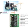
4ch%2012V%20wireless%20relay%20with%20ac%20to%20dc%20converter

I think I understand what you're asking.  The above redrawn diagram may help which shows the generalized case.  That is, the converter requires some power source (can be AC or DC) as long as it's high enough to support a 12V DC output.  Of course it's 18V track AC in your situation.

Because this is a 4-channel relay module, the loads can be separate from the converter power source...albeit they are one and the same 18V track AC in your situation.  And since there are 4 independent relays, the 4 channels can switch on/off power to 4 different accessories where each accessory can operate at a different AC or DC voltage...albeit the operating voltages are one and the same 18V track AC in your situation.

So it becomes an exercise in wiring management and what you have or prefer to use in the way of connectors...5-cent twist wire nuts, terminal strips, bus bars, etc.  But to your point, yes, there are schools of thought but even though I showed 2-wires going into both converter screw-terminals in my first photo, it's a good idea to have only 1-wire per screw-terminal and to perform any distribution/splitting externally.


Attachments

Images (1)
  • 4ch%2012V%20wireless%20relay%20with%20ac%20to%20dc%20converter

Thanks, modified my wiring and it does work and easier to make the connections.  Curious though I may have introduced another issue. 

When I turn the accessory off with the key fob and then power down the track power this causes the switch to activate, I can hear it click.  So the next time I apply power to the track the accessory is already on.

Two thoughts; I had mentioned that I am controlling power to my bricks using a key fob that controls the outlet that the brick is plugged into.  Is it possible these switches are both the same frequency and turning off the brick is also activating the accessory switch, although turning on the brick does not trigger the accessory power, only when power is removed using the brick remote

or, is there something with the 4 channel switch that when power is removed the switch is tripped, and I need to change a function of the switch, is that what is referred to as latching?  Currently each of the fob buttons turn on and off a switch as the button is pressed.  But again when power is removed the the switch activates.

Lastly, when wired to the previous diagram you provided I dont recall this issue, but I may not have been paying enough attention, was just happy it worked.


thanks

Frank


The converter board has a tiny LED on the right side (as oriented in the picture) showing it is receiving AC power from the track (or wherever).  Likewise, I don't have that specific 4-channel relay module, but I'd suspect it too has a tiny LED indicating power is applied to the board.  Are either/both of these indicator LEDs on when you remove track power?

If you are removing track power, I don't understand how the converter (and then the 4-channel relay module) can still be receiving power to activate its relay(s). 

Last edited by stan2004

They are both illuminated when power is on.  When I shut down power using the brick remote just as the those leds start to fade I can hear the switch activate.  

I do have access to one of the bricks power switches and experimented to see if turning it off without using the remote has the same effect.  It does, when the switch was flipped I heard the relay switch, and when the brick is turned back on the accessory has power.  So it does not seem to be related to the remotes having the same frequency.

Just to confirm my connections are as follows:

18v ac from track to AC inputs on converter

Converter set to 12 volts, and output wired to dc side of relay

Wire from center rail of track, hot, connected to B of channel A on relay

Wire from outer rail from track connected to accessory

Wire from C of channel A, switch, on relay connected to accessory

As I am using AC, does it matter which wire goes to which connection of the accessory.  Does not seem to matter as these terminals are not labelled in any way as far as positive or negative.

thanks

Frank


In addition, I just determined that if I turn the accessory on using the fob for the relay and leave it on while power is removed either by remotely turning the brick of or switching the brick off manually, the relay does not switch it self off as power is disconnected.

It appears the relay only switches on just as power is removed, but does not switch off when power is removed.

thanks

Frank


I determined the issue, by moving the wire from C to A on the relay it now does not fire when power is removed.  But if the relay is on and powering the accessory and the power is removed the relay turns it self off.  This is much better that having the relay turn on when power is removed.

Thanks for your help.

Frank


So for a given relay channel, you ended up using terminals A (to load) and B (from hot)....rather than C (to load) and B (from hot) as I had drawn.

Again, I don't have that particular 4-channel wireless relay but I did some more digging:

bass ackwards

The diagram on the left is from the Amazon listing that I recommended.  Specifically, each relay output has 3 screw-terminals labeled A B C in white ink going left-to-right...and per the diagram corresponds to the relay function NC (Normally Closed), C (Common), and NO (Normally Open).  For your application and for the vast majority of wireless relay applications you use the C and NO terminals to emulate the ON/OFF control of a 2-wire switch.  Hence I incorrectly showed using terminals B and C.

But in looking at other 4 channel wireless modules I found diagrams as shown on the right...where the NO and NC functions are backwards...suggesting you should use terminals A and B (as you ended up doing).  My guess is the diagram supplied in the Amazon product listing is incorrect. 

I also found a similar 4 channel wireless relay module which labels the screw terminals NO, C, NC (instead of A-B-C) which I realize cost the manufacturer 0.00001 cents more in white ink cost.   

functional labeling has its place

I can understand using non-functional (color-coded, ABC,123, etc.) labeling for consumer products but these are DIY products.  


Attachments

Images (2)
  • bass ackwards
  • functional labeling has its place
Last edited by stan2004

Time to break out the meter and see what the terminal are actually doing.

I worked with a guy once who hated to comment his code.  He felt that “Code is fact, comments are fiction.”

In this case I agree with gunnerjohn.  It doesn’t matter what the docs or the silk screen say.  Get a meter, or a lamp, and ring it out because that is what is real.  You can also find out if the relays reset to some known state on power down / power up.

Good  luck,

Bill

@EastBay posted:

I worked with a guy once who hated to comment his code.  He felt that “Code is fact, comments are fiction.”

I fired more than one programmer with that attitude!   If the comments were fiction, then he didn't know what the code was doing!  When doing development for avionics, which I did for over 20 years, if I couldn't understand what the code was doing by just reading the comments, then the code wasn't done!  As far as the comments getting out of date with code updates, that's unacceptable as well.

I fired more than one programmer with that attitude!   If the comments were fiction, then he didn't know what the code was doing!  When doing development for avionics, which I did for over 20 years, if I couldn't understand what the code was doing by just reading the comments, then the code wasn't done!  As far as the comments getting out of date with code updates, that's unacceptable as well.

I fully agree with you and have done the same.  But I also think that if things don’t  “seem right” put it on the bench exercise it and evaluate what it is doing Vice what you think it should be doing.


Frank please let us know what you find out.

Bill

Yep, the meter would be out and exercised to verify what the relays are actually doing.  That's really where the rubber meets the road.

I've worked with this stuff long enough that I had to cobble together a little set of test harnesses.  The 4-channel transmitter on the right has four buttons to trigger each channel, and the 4-channel receiver on the right has four LED's to indicate the channel status.   I just clip each of them to 5V and I can test transmitters and receivers for function and also the different operating modes.

4-chan Remote Test harness

Attachments

Images (1)
  • 4-chan Remote Test harness

I think Frank has already shown us what it is doing.  I found another listing using the same diagram but also had an additional diagram that clinches it as I see it:

nc no mislabeled

The diagram on the right shows the loads hooked up to terminals A and B which should be NO and C respectively.

The individual relays are labeled SRA-12VDC-CL which are basic non-latching relays so will connect C to NC when module power is removed.  This matches Frank's observation that as the LED-power indicator faded upon removal of power, it was then that the relay clicked OFF ...which of course turns "ON" terminals B and C (i.e., connects C to NC).

It's unfortunate that the left diagram, thru the miracle of cut-and-paste, is found in dozens of listings on eBay, Amazon, elsewhere. 

Attachments

Images (1)
  • nc no mislabeled
Last edited by stan2004

Add Reply

Post

OGR Publishing, Inc., 1310 Eastside Centre Ct, Suite 6, Mountain Home, AR 72653
800-980-OGRR (6477)
www.ogaugerr.com

×
×
×
×
Link copied to your clipboard.
×
×