Looking for a replacement belt for my MTH 30-9022 Dispatching Board. Original belt does not aged well. Also looking for an exploded diagram of this accessory.


|
|
Looking for a replacement belt for my MTH 30-9022 Dispatching Board. Original belt does not aged well. Also looking for an exploded diagram of this accessory.
Replies sorted oldest to newest
MTH has said that the belt is not available. I tried to make one up but had no success.
Bob, John:
I am having the same problem. Motor turns but no movement.
If you find a solution please share with the board, I will do the same.
Charlie
If you can Get the belt out. To see if it an 0 ring. Or flat belt.
A seal and packing business can match it up. Did that with the saw mill belts. And I have extras of those..
This accessory is a disaster. I have tried to replace the belt which is made up of two parts held together by two fine fine metal pins. The pins extend above the edge of the belt and moves the man back and forth. Unfortunately, the replacement belt which I finally got from Brasseur trains in Saginaw, Mi. looked like it would work fine, but was too stiff to navigate the end spindles and would simply stop. Also, lots of sharp metal edges to cut yourself on inside this monster. I finally gave up and put it in the "maybe some day I'll try again pile." No substitute belt would work because it wouldn't move the man back and forth. The replacement belts were too stiff so don't feel bad that you couldn't get one. Notice how the accessory has disappeared from the catalogs. It's because it doesn't work for very long without aggravation.
turbgine posted:It's because it doesn't work for very long without aggravation.
I've seen public layouts with it displayed and operating properly for well over a decade.
I think the belts die from inaction, not from use.
Looks like it's modification time. Must be a way to separate the 2.
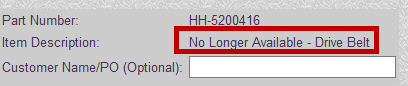
The part is available from MTH as part number HH-5200416. Web link is here:
https://mthtrains.com/part/hh-5200416
I have one of these which, even with the replaced belt, has been a mixed bag. In our club another member came across one, replaced the belt, and got sketch results as well. They have not held up to show usage. The gear train looks solid but for some reason we have not had good luck with these.
Nick C.
It's listed, but it's not available.

Because the belt is comprised of a white nylon material and is in two halves secured together by two steel pins the point where the two halves come together have to navigate the spindles at each end results in a hangup of the belt at these spindles. So, then the motor turns but the belt fails to move. The belt need to be more supple so it can wrap around the spindles without binding. I don't know who made the original belts, but the MTH replacements were crap. They simply didn't work and they were expensive.
I talked with Mike about this at the last York show, since my belt shattered into about 6 pieces. He stated that is was not economical to make another run of belts. So for now, MTH is out as a part source. The belts die from age, whether or not the accessory is used. Just a poor part, IMHO. So I've been looking at belts used for robotic applications.There are some out there that may work, but everyone I've found requires some degree of modification to either the belt or the pulleys. Keep looking, guys (and gals!). A solution is out there waiting to be found.
Oh, and forget about trying to find a parts diagram. The accessory was issued well before there was any thought given to exploded parts diagrams.
Chris
LVHR
Thanks for everybody that reply. I picked this up for a couple of dollars at a local train meet. Thought it was worth the challenge and to just take it apart. The previous owner told me about the belt and the availability issue, but for $2, I couldn't past it up.
Couple of questions about its operation. Does it use a momentary contact switch? Does the man travel to the other side, turn around and pause before traveling back to his starting position? This would explain the 2 pins on the belt. Do you need to hold down the switch the whole time it operates, or just long enough to get the man started.
When I took it apart, a small piece of the belt was inside, about 1/2" long. It broke apart when I touch it, but I did get some measurements off of it. Don't know if this was stored in a warm area which could be part of the cause of the poor condition of the belt.
I always wanted this accessory. I'm glad I balked on getting it. Quite a sad description of Mike Wolf's answer: "its not economical" to make replacement belts! Geez. How about re-releasing the dispatch board, along with an improved/durable belt, which can also replenish MTH's parts supply?
FWIW, we have been using off the shelf belts to fix these. The belt is T5 pitch, 12.5mm wide 66 0r 67 teeth. We drill a hole in one of the teeth using a micro drill bit of 0.75mm diameter, and then press in the original long pin. In addition, a collar is used on the pin to set the forward distance the belt can move towards the siding gantry. The reason is it's near impossible to get a belt with a ridge in the middle as a guide, but it's not strictly required and with some attention an off the shelf belt can be used. While this is a 16mm wide example, at worst it hangs off the front edge of the pulleys, but may not then need the collar https://www.amazon.com/Gates-T...Length/dp/B00CJFSLMI
I was hoping I had pictures of the belt in place, but it was done at a friends house. All I could find was measuring the pitch of the original belt and then the video of it working after the replacement belt was installed.


Again, when I first saw one of these with the broken belt, I said one of 2 ways I know to fix this:
#1 use an off the shelf belt and modify as required to make it work- hence a T5 belt and drill the hole for the pin in a tooth- and this works amazingly well and tested on 2 units. T5-330-12 Synchro-Power Polyurethane Belt, T5 Pitch, 12mm Width, 66 Teeth, 330mm Pitch Length
or
#2 make a 3D printed belt, since TPU and other flex material are much more common. OpenSCAD is one easy way to make the CAD design of a printable belt and even could have the ridge. I started on this, but stopped after the T5 belt worked so well and was cost and time effective. I will share the files I started when I get a chance.
Just got the install pictures from my friend. The collar is just used on the pin to prevent the belt from sliding forward off the pulleys. Crude but effective instead of a rib inside the belt.


Great idea to use an off--the-shelf belt, I'm going to keep this in mind. ![]()
I am curious as to how this whole thing works? What does the pin do?
Big Jim posted:I am curious as to how this whole thing works? What does the pin do?
The belt simply rotates a complete loop. If you watch the pin from the side, it moves in one direction, stops horizontal motion at the pulley, then turns and moves the other direction creating the back and forth motion of the figure. The pin simply is the method the belt transfers the motion to the slotted moving gantry with the figure. Think like a crankshaft that converts rotary motion to linear reciprocating motion, but the belt is an oblong crankshaft, and the resulting motion is extra long linear motion. The pin is literally the pin of the crankshaft. Go back and look at the pictures I posted earlier. The pin is just stuck into the side of the belt. The belt then is stretched over the 2 pulleys. The motor only turns the belt one direction however, in doing so, the pin actually moves back and forth when looked at from the front. That pin pushes the little rolling carriage on the metal rail via a slot, which is what allows it to make the full 360 loop rather than having to reverse the motor. The limit switch is there to park the belt and thus figure at the one end. You press the button, the motor turns the belt, the figure moves down the track to the end, then pauses for a second as the pin now slides down in the slot following the pulley turn, then pulls the carriage back until it hits the limit switch and stops, thus externally the little man parks at one end, then then commanded to "change the board" moves down until the end- then due to the slot has a minor pause, then moves back to the starting point and stops. The little carriage has a rack and pinion shaft such that the brass rack rod hitting the endstops at either end of the travel turns the little man on the shaft to face or walk in the direction of travel. The motor turns the belt, the belt pin drives the moving carriage, the moving carriage carries the little man.
Access to this requires an OGR Forum Supporting Membership
