
Morning guys:

A couple of months back I discovered that both of my newly acquired Z4000 transformers did not reduce power all the way down to zero, as I lowered the throttle handles (old thread on OGR Forum). Turns out this is not uncommon. My transformers will get down to about 7 volts, and then drop to zero immediately the throttle handle is slowly moved south.

This is causing problems with a couple of my PS1 loco's (early QSI boards) in they won't come out of "neutral" to move forward upon start-up. Thank you Jon G. for the background info on these early QSI boards.

Anyway, I have since learnt the problem can be overcome by fitting a "resister" on the output variable posts to slowly reduce the voltage from 7V down to zero gradually.

Went to my local electronic store (Jaycar) here in Australia, and told them what I had been told, and they just looked at me as if I was from another planet!!!  Seems I have to tell them the type of resister I need, as these things are made for all types of applications, and I need to know the "rating" of the resister I need.

I left the shop more confused than what I was when I entered it.

Bottom line......can any of the truly smart, intelligent, electronic techs on the forum tell me exactly what part number/code/identification symbol I need to go back to "Jaycar" and get the right resister I need to fix my problem??

I have no idea what "resister" I need......I am like a Diesel Fitter....I can install anything on a machine, but I certainly can't figure out what the exact part number I need should be!!!

Peter.....Buco Australia

Original Post

Replies sorted oldest to newest

You have what is known as voltage leakage. There actually is a simple kit that adds capacitors to the input of the gate drivers of the FETs and corrects the issue. However, since you are located where MTH techs and support could be a costly problem (I've read a lot of your posts and problems)  you are looking for external help. Forum post https://ogrforum.ogaugerr.com/topic/z-4000-repair

I did my own and here is a picture

562760

Here is an edited diagram

562734

562738

OK, so say you cannot or do not want to modify the transformer and I fully understand and support that.

What you do not want is a fixed value resistor. Just understand why here. Ohm's Law and basic math doing power conversion to heat. If you put a fixed value resistor it cooks off more heat energy the higher you raise the voltage. Somewhere between being a burn risk and maybe being a fire risk, this is not how to do it. Yes, most basic power resistors do change value as they heat up, but normally this is not enough to prevent damage or excessive heat dissipation.

What you need is a self regulating resistor. Guess what? They exist!!! It's called an incandescent light bulb. The logic here is, the filament is one resistance (low cold resistance) starting out. This would effectively short out the leakage voltage. However, once you start raising the voltage, the filament heats up (hot resistance value) and will then increase resistance thus actually attempting to maintain a lesser current that what the cold resistance would suggest. This gives the short we want to shunt the voltage leak, and yet that same lower value cold resistance automagically rises to a more reasonable level as soon as the filament rises in temp and begins throwing off heat and light. This is the trick why a properly designed light bulb doesn't just burn out instantly.

A typical example would be to use an automotive 14V lamp. A brake lamp would be the most current however, might kick off significant heat depending on how high of a voltage you typically run in conventional. So something somewhere between oh say a turn signal lamp bulb or other bulb might be far easier to source and more correctly not melt something or become a fire hazard or burn hazard. Again, really you just need a decent 12-18V rated bulb that draws enough power to fix the leak, and not so much power it's getting hot (burn risk) or melting something.

Last edited by Vernon Barry

Buco,

It sounds like your Z4000 is behaving as it should. As the voltage is turned down, it should suddenly drop to zero as you pass the 6 - 7 VAC range. My Z4000 behaves like this as does my old Lionel ZW. The PS1 can be a persnickety engine. Make sure you have a BCR installed to replace the battery for best performance.

If you absolutely need a proportional control that won't jump down and will slowly drop voltage as you turn the handle, the work-around solution is rather easy. Just output a fixed voltage from the Z4000 into an MTH Z Controller box costing about $85 USD.

(Picture from PatsTrains.com)

To be more technically accurate to your initial question, and if you were inclined to build something, the component you needed is called a thyristor rather than a resistor. (There are also other semiconductors that will work.)  A thyristor would control AC voltage without wasting energy as heat. In fact, all my sidings are controlled by a type of thyristor. The Z Controller above behaves as an off-the-shelf and more expensive version of a homebrewed semiconductor circuit.

Hope this helps.


Attachments

Images (1)
  • mceclip0
Last edited by Bruce Brown

Sorry, realizing I misread or misinterpreted the initial post. I think the assessment of the problem is wrong, but not being there in person to see first hand and actually test these locos and your Z4000.

The point is, I remember distinctly when you got the Z4000 and followed these topics. I was not a forum member during that time so I could not reply.

https://ogrforum.ogaugerr.com/...7#161349519396080797

also here https://ogrforum.ogaugerr.com/...1#159237712048002711


What is the serial number on your Z4000?

Last edited by Vernon Barry

Thank you so much for the speedy replies.

VERNON:  Thanks for the component fix, and photos of the alterations to the internal circuit board of the Z4000, but this is well above my paygrade. And I now realize there will be an awful amount of heat generated by a resister, and that will definitely become a fire risk. We won't go down that slippery slope!!!

I will try the brake light bulb trick tomorrow. I have some brake light bulbs for commercial trucks that run a 24v system, so they should work fine......yes?? I'll let you know the results tomorrow.

BRUCE:  I'm interested to know more about this "thyrister" thing. Can I purchase it from my local electronic supplier, or is it a "special order" thing? Does it get installed externally on the variable terminal posts of the Z4000? If it is a standard off the shelf component, can you tell me the code number/identification label etc. so I can see if the boys here can supply me with it.

Also, thanks for the suggestion about hooking-up a Z1000 to the fixed output of the Z4000, and using it to run my trains, but that was the whole point of the exercise in getting me a Z4000. I want to dispense with the Z1000 and use the re-programming buttons on the Z4000, as well as the special MTH hand-held remote that works in conjunction with a receiver that plugs into the Z4000.

Peter......Buco Australia

Peter, another thing I noticed in watching your videos of this problem was you were not waiting long enough at zero.

I suggest waiting a 2 count (1, 1000, 2, 1000 and saying it out loud) then raising the handle or using the direction button..

Here is my technique.

Raise the throttle to 9V (indicated n the Z4000 display). Wait at least 30 seconds since you have BCRs listening for the sounds.

Press and hold the direction button for a 2 count.

Upon releasing the button the locomotive should switch to forward with an audible relay click and then the engine should be attempting to move at a relatively slow speed.


Again, watching this video, I just feel the engine never really saw zero long enough to detect it.

https://ogrforum.ogaugerr.com/...2#159660138894000522

Also, another detail regarding technique. If the starting voltage is too high, then the engine also will not come out of reset. I just now tried this with a PS1 loco. On mine my transformer is a more recent Z4000 and I'm using the Z4000 remote control. If I raise the track voltage to 14V displayed on the face of the Z4000, wait 30 seconds, hit the direction button it does not come out of reset. However, if I follow the use of using a lower voltage, say 9 or 12V displayed on the Z4000 meter, then the engine will come out of reset.

Because there could be minor variation in meter readings. My advice is start with a lower indicated voltage. Try 10V when first powering the engine, again wait your 30-60 second time period, then press and hold the direction button for at least a 1 count and maybe a 2 count, then release.

Again, there are a lot of rules. You cannot have too high of a voltage as the engine detects this to prevent a high speed runoff when the engine does switch into gear. You must have a defined time of absolute zero voltage for it to detect that as a command- not just you varying the voltage. Either of the scenarios gets you into setting functions rather than leaving reset.

Last edited by Vernon Barry

https://ogrforum.ogaugerr.com/...2#159660138894000522

Again, in video 0061, your starting voltage was 12V and lowering the handle. You did it so slow and the difference between the high starting voltage and the slow lowering triggered the setting function hence the bell ding. You also did not stay at zero nor achieve zero.

In video 0065 you lower it to 8.5 volts displayed, but you failed to press the direction button long enough to again achieve true zero or it's just not registered by the engine long enough.

I was able to get my engine to act up by either starting with too high of a voltage or not waiting long enough at zero.

Also, not seen in you video you can mess up by again, raising the voltage too high and then lowering it. This is interpreted as making a setting VS trying to leave reset. In other words, I could replicate by raising the throttle to somewhere between 14-16V indicated by may Z4000, then lowering to say 10 or 12 and the engine detected this as a setting command. This means a part of the technique is do not raise the throttle too slowly or too far and then lower it as that can be interpreted as you changing a setting in the PS1 firmware.

Raise to 10V. Don't slam it, but also do not raise too slowly. Don't overhsoot the mark and then lower it.

Wait the time period to ensure the BCR is charged.

Ensure either using a bulb as load or if your Z4000 is not an early version ensure you actually get and sit at 0V on the track long enough to be sensed as true zero by the engine. Failing to achieve true zero long enough just looks like a setting command to the engine.

When raising the voltage, again, doing it too slow from 0 is not good but don't go past about 12V as raising too high is seen as a jackrabbit start and the engine might ignore that too.

Last edited by Vernon Barry

Also, you asked, a 24V bulb may or may not work. I might be the perfect thing, actually I just don't know. A brake light is typically a higher wattage bulb (more current at a given voltage). A 12V bulb -especially the brake bulb would draw some power.  That said, you voltages you are running at conventional are fairly low and more load is good in that it makes the output of the Z4000 lower. A 24V bulb has a higher resistance since it's rated fo double the source voltage.

So specifically, a 24V brake lamp might be just the ticket. A lesser bulb like say a turn signal or marker light or dome light rated for 24V might not be enough load at these low voltages. So again, specifically a 24V brake light, I would give it a shot. If you can get a socket and try different lamps- 12V or 24V, just see why amperage they draw at a given voltage in the ranges we are using starting at the lowest value the Z4000 puts out, and then raising it to say 16V max.

Last edited by Vernon Barry

Morning Vernon:

Thank you for the suggestions on how to coax the Z4000 into running my PS1 "problem children".

I followed your suggestions and did not take the voltage above 9V, waited 30 seconds, then hit the direction button, and held it for 2 seconds (counting like you recommended).

Result: Zero, zip, nada, nothing!!! It remains the same....one bell ring and no movement.....the loco just sits there looking at me with its lights on!!

Switch back over to the Z1000.......apply track power to 9V......wait 30 seconds.....hold the direction button down for the count and, low and behold, the loco comes out of neutral and starts moving around the track, just like it should.

Gotta have something to do with the sine wave emitted by the Z4000, and these early QSI boards not reading it properly. Jon G (MTH tech) said there were some funny things occurring with the very early QSI boards installed in RailKing and other brands of loco's.

Serial number on my Z4000 is: 121044289  if that is of any help.

Hope the video plays so you can see how I followed your recommendations to the letter.


At this point (just like last time) I GIVE UP!!!!

Peter......Buco Australia

Attachments

Videos (1)
MOV02857

Good news is, yours is the later revision. https://ogrforum.ogaugerr.com/...5#126718808002937895

"The first two digits indicate the month of manufacture and the second two digits indicate the the year of manufacture.

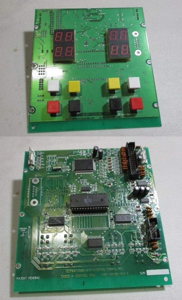
A serial number that begins with 0398 was mad in March of 1998, this is the first run of Z4000's ever made.

H1000"

Serial number on your Z4000 is: 121044289

Decoded = December 2010 serial 44289

Again, sorry for your troubles but yes, some of those early PS1 chipsets (it's the firmware on them, not so much that the board or chip is bad), are really picky.

I was surprised to watch your video and hear the ding and the increment to the double ding on the next button press.

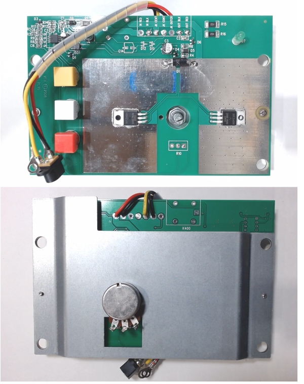
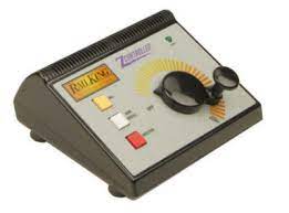
Being honest and working on these transformers, it's not like I have fully reverse engineered them but they somewhat contain a similar circuit (Zcontroller VS Z4000). The Z controller uses 2 MOSFET transistors to control the AC output and the Z4000 also uses MOSFETS. Yes, how they are controlled is much mroe complicated on the Z4000 but the idea was that more attempts to make it replicate true sine wave output.

That said, one more test and part of the reason you likely wanted a Z4000.

Use the program button and attempt to factory reset this problem loco since with all the attempts we may have set settings by accident.

Make sure both handles are down and the loco is on the track. Also, since you have BCRs, what you typically do is power the engine for a bit (say 60 seconds) at 10V, then drop the handle, let the engine completely shut down- thus mostly retaining a charged BCR.

So again, you must start this with both handles down.

Press the black program button on that side of the Z4000

Now use the white whistle/horn button to increment up until 18 is displayed (down is the red direction button)

Now press the yellow bell select button

the transformer will power the track, wait a few seconds and the engine sounds will start up, then it will rapidly raise and lower the voltage on the track which should be registered as wooshes counting up to 18.

Then the engine should respond back with 3 dings and 3 dongs. *Just as a note, if it does not give 3 and 3, say 3 and 2 or 3 and 1 it's means the wooshes were missed- and you can fix that by incrementing up the count from 18 by using the white whistle/horn to say 19 or 20, then press select again which sends the 1 or 2 more voltage raise and lower causing more wooshes and then the board should respond back with the appropriate 3 dings and 3 dongs. If you go too high, and get more dongs like 4, just again, lower now to 18 (using the direction button to increment) and hit select again. The point is, there every once in a blue moon is a mismatch where the engine doesn't register or see the cycling and is off. The cool thing is you can increment without having to start completely over. That said, an overshoot does do the program sequence all over again to the lower count, but typically, it's just that you missed one or two and so there is an easy work around to properly get the 18 reset.

Once you get the 3 dings and 3 dongs, then hit the program button again and this ends program mode and powers down the track. Obviously wait for the engine to fully power down and give the fart sound.

Just trying to see if the one major function and a good reason to have a Z4000 for PS1 engines works for you. Reset programming using the program button is so much easier IMO.

Thanks again Vernon:

Glad the video worked, and you could see for yourself I was doing the sequence right.

I have yet to try the "stop light" bulb experiment. I'll do this later this afternoon, and report back tomorrow.

On the subject of the different Hz's between Australia and the US......this theory doesn't hold water, as far as I can tell. All of my MTH loco's operate perfectly when I use the Z1000 transformer. If the Hz was an issue, the Z1000 would not work either, and I have 2 of them in service on my extended layout......one on the main line loop that you see in the video, and the other on my freight/fiddle yard that isn't connected to the main line....yet!!

As one of Australia's most famous comedians (Paul Hogan) once said: "KEEP A DANCING MARIA!!!"

Peter.....Buco Australia

Although the Z1000’s work fine do we know what the differences are internally between them and the Z4000? Could the Z4000 have boards that are designed to take into account the frequency coming in for specific functionality?

I did notice on the MTH website that it says the Z1000 is for 60Hz and the Z4000 doesn’t mention frequency at all.

Is it worth throwing MTH an email asking if the Z4000 is 50Hz compatible?

There should be no problem with the Z-4000 on 50hz, at least MTH doesn't think so.  Since the Z-4000 synthesizes the A/C waveform, the 50hz isn't a big deal for it.

From the User's Manual.

If the starting voltage is a problem for your PS/1 engines, may I suggest a really easy solution?

Use a 10 amp bridge rectifier and do the following.

Tie the + and - pins together.

Put the bridge in series with one power lead using the two ~ pins.

This will drop the starting voltage about 1.3 - 1.4 volts.  If you need more drop, use another bridge rectifier in the same way and you'll drop the starting voltage around 2.6 - 2.8 volts.

Attachments

Images (1)
  • mceclip0
@Ukaflyer posted:

Although the Z1000’s work fine do we know what the differences are internally between them and the Z4000? Could the Z4000 have boards that are designed to take into account the frequency coming in for specific functionality?

I did notice on the MTH website that it says the Z1000 is for 60Hz and the Z4000 doesn’t mention frequency at all.

Is it worth throwing MTH an email asking if the Z4000 is 50Hz compatible?

Let me see if I can tie together a couple of various topics and comments in this discussion.

The ways to create a variable AC voltage from a fixed voltage.

#1 The old school way- a transformer core wound with exposed secondary windings that a roller or wiper can tap into ever increasing turns of windings thus increasing the output voltage. Basically every postwar transformer and a few and somewhat limited selection of modern ones. Example MRC made the MRC Pure Power AC transformer, model AH501 or the ATLAS and rebranded Williams 80watt are 2 I know of with this type of construction.

Williams #WIL1000080 80 Watt TransformerMRC AH501 O Scale 130 Watt Pure Power Transformer – TrainzZW Question | O Gauge Railroading On Line Forum

#2 Rheostat variable resistor. The problem with this is that a massive amount of energy, sometimes as much as 50%, is turned into heat. So if your train uses 3Amps of current at say 12V, then we might be dissipating about an equivalent amount of heat 36 Watts. This is why are are not commonly used in O-scale because at the power level many trains need to run, the heat loss in the rheostat that it has to dissipate is dangerous. Think about a 30 watt soldering iron as a reference point.

Image 1 - VINTAGE LIONEL # 88 BATTERY RHEOSTAT w/ ORIGINAL PLATE & PAINT or a more modern 25 watt rated example that probably would fail Ohmite RHS500E

#3 Electronic control using a "Thyristor" which can also be a TRIAC, or other similar component. A key feature of this is that it is a transistor that has a gate that turns it on and in most cases, it stays on until the voltage across it goes to 0 known at the zero crossing. They use a circuit to delay the triggering on state to clip the original source AC waveform. In other words, they are cutting out part of the AC cycle and thus this causes distortion from the original wave form. This is called chopping. Again, while the thyristor or TRIAC is a major component, there must be supporting circuitry to change when the device turns on during the waveform. Examples that use this are K-line Powerchief 120 watt, Lionel CW80s, MRC 027, just to list a few. Again, these are not recommended for MTH PS1 electronic engines because they create a pretty distorted waveform. These are often obvious because there is only one large heatsinked transistor device (typically a TRIAC).  A CW80 has one TRIAC per channel since they have a track variable channel and an aux power power output.

cw-80 disassembly tools | O Gauge Railroading On Line Forum 
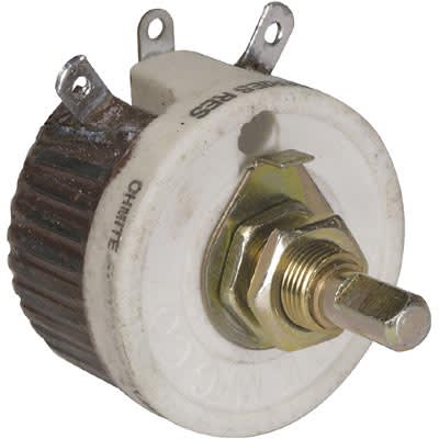
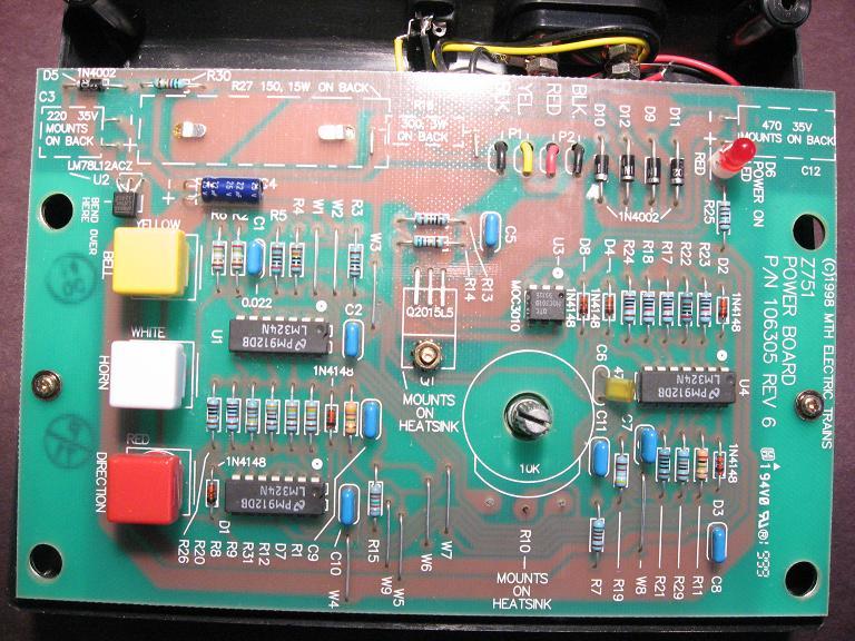
Another example is an MTH early Z controller that only has a single TRIAC (Q2015L5) in the center that mounts to the aluminum heatsinkTRIAC circuit to control PW | O Gauge Railroading On Line Forum

#4  The more advanced method of using 2 (or more) MOSFET transistors per channel to handle the negative and positive swing of the AC waveform. That said, they still need advanced circuitry or a microcontroller to sense the AC incoming wave and then time and trigger the gates of the MOSFET transistors to conduct a specific portion of the waveform. The idea is, more components and details, but better control and smoother output than a TRIAC based output.

Modern recent MTH Z controller uses 2 MOSFETS instead of the previous single TRIAC.

the Z4000 power control board. There are 8 total MOSFETs for the 2 channels.

mceclip1and the FET side that faces the heatsink

And then the front panel board that drives the power board

Attachments

Images (2)
  • mceclip0
  • mceclip1

Morning gentlemen:

OK......FROM THE TOP!

VERNON: I tried the 24V stop light bulb trick, and it did drop the voltage down to about 5V, before continuing to immediately drop to zero. Tried to get the PS1 loco out of neutral using this light bulb system....NO CIGAR!!! Just sat there doing the same old same old, one ding of the bell, and nothing.

Moving on....did the reset function (18) using the buttons on the Z4000, and everything went to plan.....got all of the wooshes and sound effects (3 dings & 3 dongs), and then tried again to get the loco moving. NOTHING, NADA, SILCH, SIP!!! Continues to just sit there and stare at me.

GUNRUNNER JOHN: Thanks for clearing up the confusion about the Hz rating between Aussie power and US power. I couldn't see how this could be a problem, considering the Z1000 works just fine on our power.

Anyway, I'm up for a challenge, and will have a go at installing the bridge rectifier you have suggested. Watch this space!!

BRUCE: Thanks for the info on the availability of these little suckers at Jaycar. Guess where I'm heading later this afternoon. Oh, and by the way, forgot to mention in our E-mail communications we have driven right across the US - east to west - taking in the full Route 66 trip on one of our visits.....you have a truly magnificent country and sooo different to driving across Australia (desert, and nothing but desert).

VERNON (again): Thank you for the simplified drawing of how to install the bridge rectifier/s - this gives me the confidence to "have a go". Watch this space also.

Peter......Buco Australia.

I use a Z-4000 on all sorts of QSI, MTH PS, and the OEM variants for test and repair.  I have never had a problem running an engine.  You can put a voltmeter on your track besides what the Z-4000 provides.  You can select DC or AC and test in both venues.  Operate the train via lever and the direction button.

You have to have either an AC or DC leakage if the engine is not seeing a drop of voltage to zero.  Or else the wave form out is corrupted.  I assume you could take your Z-4000 to an electronic tech or school to see the output on an O scope.  G

Morning Gentlemen:

In the words of that Sony and Cher song......"and the beat goes on!!!"

Well, all I can say is that little exercise got me no further in getting that PS1 loco to move.

Went to Jaycar, got the bridge rectifiers (4 of them) as recommended (thank you Gunrunner John, Vernon, and Bruce) installed one of them to the back of the Z4000, and it did lower the voltage slightly, but not enough to make any difference to the loco.

Installed two inline (daisy chain) as per Vernon's diagram, and still nothing!! The loco still just sits there, and won't move out of neutral.

I am now leaning more toward what GGG has hinted about in his above reply.....a corrupted sine wave. When I shut the loco down, the shut-down sounds are funny. The sound of the diesel engine idling is missing for a couple of seconds, and then it comes on briefly, just before it disappears again, then the silence is broken by the faint "fart" sound.

This interrupted sound effect does not occur when I shut down using the Z1000. The loco sits in neutral (once I interrupt the direction of travel) with the diesel motor idling, and then slowly shuts down once I turn the track power off, followed by the short silence, and then the "fart". I think some of these early QSI boards are really finicky, and won't read the signal emitted by the Z4000.

BOTTOM LINE:

In the words of Harry Callahan (Dirty Harry) ...."A MAN'S GOTTA KNOW HIS LIMITATIONS"....and I now know mine!! Let's put this baby to bed, and I will learn to live with the couple of "funny" PS1 loco's I have. I will have to keep the Z1000 on the control deck, just to run these loco's.

Thank you one and all for your input, especially Vernon who has really stepped-up to the plate with so much knowledge and info on transformers.....it has truly been appreciated.

Good night all.

Peter.....Buco Australia.

Add Reply

Post
This forum is sponsored by MTH Electric Trains

OGR Publishing, Inc., 1310 Eastside Centre Ct, Suite 6, Mountain Home, AR 72653
800-980-OGRR (6477)
www.ogaugerr.com

×
×
×
×
Link copied to your clipboard.
×
×