
Wondering if anyone has invented a solution for this yet, a SIMPLE solution.

I have a couple of Fastrack O-72 wyes, but I would like to reverse the "through" and "out" positions of the controller. Easy enough to swap the red and green leads so the handle works the right way, but the LEDS are still reversed! Trying not to modify the controllers, which is the obvious answer. Has anyone invented a clever circuit to reverse the polarity of the yellow wire? I have a couple thoughts, but trying to see if this has already been done, Will give a Gold Star for simplicity and elegance. Would not mind modifying the switch itself if it can be done reversibly.

Thanks in advance for your ideas. 

Last edited by PLCProf
Original Post

Replies sorted oldest to newest

PLCPROF,

If I'm understanding this correctly... the problem is that the lights on the controller always show green for straight, and red for curved, and you want to reverse this without modifying the switch or controller.  

I don't have a fastTrack switch to test this on, but going off a schematic of the insides of the controller from a post a few months ago, I am guess ing the lights are controlled by a 0-5VDC signal on the yellow wire.  It would be wise to pull out a meter and measure voltage across yellow and black with the switch thrown in each direction to confirm this, but it is my guess based on the drawing I have. (LEDs powered between yellow and black with a diode and a 470 ohm resistor in series.) My solution will still work as long as the voltage of yellow is in fact DC, and is less than 40 volts, which I'm sure it is... the value of the resistor may have to be changed, however.  

It should be as simple as inverting the signal on the yellow wire in such a way that it can still sink and source enough current to power the LED's I'm going to clock in with 3 components.  An NPN transistor, A PNP transistor, and a resistor.  

Here I am depending on the circuit from the switch to have enough current to power the transistor and the LEDs.  Given normal gain for a 2 cent 3906, it should only add a milliamp or 2... probably a lot less.  

All the other wiring stays the same besides this circuit placed in series on the yellow wire, and needing a connection to black.  

JGL

P.S. giving free online schematic tools a try over my usual chicken scratch hand drawn stuff.  

I am always interested in gold stars.

Here are some photos of an O72 switch internals. If you look at the connectors on the board in the first photo, one can see in the second photo that the two inner most connectors get the feedback from the limit switches. (indicates position of points, stops motor, and changes next motor rotation direction, )

Therefore, if you swap the limit switches, (the two little black thingies) it should feedback that the opposite orientation is thru when the segment gear bumps it.

There should be enough slack in the wires to move them. After moving them, physically push the segment gear to the opposite side or follow the the switch it was touching to keep the physical and electrical state synchronized. Note that the part number is up one side to keep the switch levers in the same orientation. (Change sides and flip over)

This can be returned to factory state when desired. No need to change the controller connections or modify the controller. We're just telling the board that THRU is when the points are on the other side.

Pay no attention to the fact that this person had the controller connected improperly.

Oops! I just noticed the switch wires most likely are twisted around the track wires. You could unsolder the track wires to untangle the switches if necessary and solder them back on when the switch is free. Always something to add work.

Attachments

Images (2)
  • FasTrack Switch Board
  • FasTrack Switch Board 2
Last edited by Moonman

Addendum:

it may be as simple as swapping the two center connectors to the board. It looks like it does the same thing as moving the switches. Then, move the segment gear to the opposite switch.

Other problem: Now, how to orient the switch lantern properly. It appears after checking one of the switches that I have, that there are two notches permitting a 90° rotation to indicate thru on the formerly out position and the lantern will seat properly.

The limit switches do stop the motor and signal direction change. When one of them fails, the switch stays in that position and chatters as the motor direction wasn't reversed. The board senses the trigger. A somewhat common problem.

I don't have any off the layout or I would test it. This could also be useful in another situation where some put the mainline on the out of a regular switch needing the same change for the manual controller and lantern lights to be green on the out.

It would also be interesting to test how the new LSU switch positon unit would read this state.

Let us know the result.

Moonman posted:

The limit switches do stop the motor and signal direction change. When one of them fails, the switch stays in that position and chatters as the motor direction wasn't reversed. The board senses the trigger. A somewhat common problem.


Yes, I understand that, but the question is whether the limit switch that illuminates the green "through" light will stop the motor when it is moving in the "out" direction, because that is what will happen if I reverse the switches! I will try it; I give it 50 - 50 odds at this point.

Thanks again for all your help!

Last edited by PLCProf
JohnGaltLine posted:

PLCPROF,

If I'm understanding this correctly... the problem is that the lights on the controller always show green for straight, and red for curved, and you want to reverse this without modifying the switch or controller.  

I don't have a fastTrack switch to test this on, but going off a schematic of the insides of the controller from a post a few months ago, I am guess ing the lights are controlled by a 0-5VDC signal on the yellow wire.  It would be wise to pull out a meter and measure voltage across yellow and black with the switch thrown in each direction to confirm this, but it is my guess based on the drawing I have. (LEDs powered between yellow and black with a diode and a 470 ohm resistor in series.) My solution will still work as long as the voltage of yellow is in fact DC, and is less than 40 volts, which I'm sure it is... the value of the resistor may have to be changed, however.  

It should be as simple as inverting the signal on the yellow wire in such a way that it can still sink and source enough current to power the LED's I'm going to clock in with 3 components.  An NPN transistor, A PNP transistor, and a resistor.  

Here I am depending on the circuit from the switch to have enough current to power the transistor and the LEDs.  Given normal gain for a 2 cent 3906, it should only add a milliamp or 2... probably a lot less.  

All the other wiring stays the same besides this circuit placed in series on the yellow wire, and needing a connection to black.  

JGL

P.S. giving free online schematic tools a try over my usual chicken scratch hand drawn stuff.  

Well, the yellow wire on the Fastrack switch alternates between plus and minus 5 volts with respect to black, the controller just has some diodes to switch LEDs according to yellow wire polarity. Your circuit is interesting, but I don't understand it! Can you explain it?

It seems my assumption was a bit off,  a +5/-5 swing actually makes more sense.  I was counting on the swing of the AC to do the reversing of polarity on the common side. Turns out my head wasn't screwed on right in the previous diagram anyway as the +5 had no supply. 

It seems like reversing the internals of the switch may just be the simplest solution, as it should also reverse the indicator on the switch it's self.  

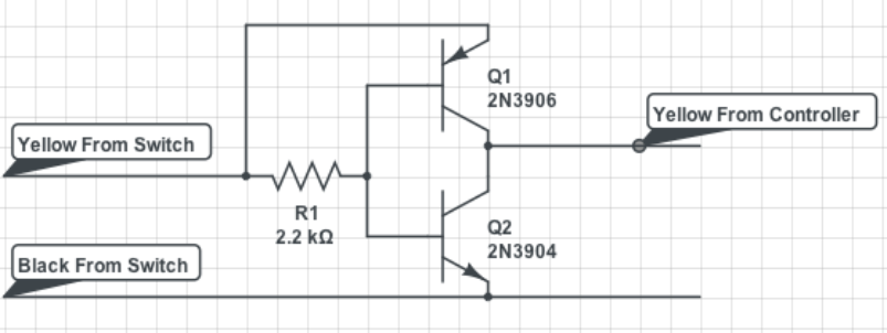
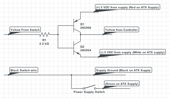
As far as only inverting the lights on the controller, and not changing anything inside either part, the 2 transistor method will still work, you just need a +5/-5 supply voltage.   Now you could go about building one, but that is a big pain in the you know what.  You can also buy negative 5 volt converter boards for 5-8 dollars on the auction site.  Add a couple dollars for the positive 5 module, and be good to go.  My solution is to use a power supply from a junk computer.  Any power supply from any PC  made in the last 20 years will do, though a brand new el-cheapo $15 one will also work.  You also get a 15 AMP 12VDC circuit you can use for lighting or accessories, and a 30+ amp 5VDC line that can power any electronic wizardry you may want to run.  We also get the -5V line for the switch controller lights.  It's worth noting it's only a half amp, so you can only drive maybe 5-10 switch controllers off it.  if you got a bunch, building your own supply may be easier.  

Anyway the circuit is mostly the same, with added external power supply.  

I think this one will actually work, but have prepared for failure.  Is there such a thing as a rusty brown star? 

JGL

Edit, a flaw has been pointed out to me off-forum, and it seems as shown the circuit will not work.  I'm thinking the flaw could be fixed with a pair of diodes, one on each transistor's base, but, I'm not sure about that yet... Think I might have to start from scratch on this one...


Last edited by JohnGaltLine

An op-amp is certainly a direct and straightforward way to do it, but the power supplies are a pain. If I had some other use for them it wouldn't be so bad, but seems like a lot of fuss for a few lamps.

Actually, I am testing an idea on the bench now. Looks promising. Seems unfair to give myself the Gold Star, though.....

cjack posted:

I found it easier to unsolder the LEDs in the controller and swap them green for red positions. I didn't swap the ones at the bottom base of the controllers so as to remind me they were reversed. But it is satisfying to see green when the switch out is on the main line.

If opening up the controller is an option it is just as easy to unsolder the two diodes reverse the polarity of each and solder back.  This will get the desired result and keep the lights in the same physical location so as to match other controllers....

Anyway, Didn't have work tonight due to snow up here in Flint, MI.  I had my 'messing around with arduino's electronics kit with me, so I actually tested  this one.  Living in a hotel for the week, so this one is quick and dirty...

It actually works this time: (mostly...)

As a note, in my example I might have the LED's backwards from proper, normal, operation, ex: which one is on with positive, and which with negative on yellow wire. I have green on positive and red on negative.  In either case, the 'mostly' comes in in that the LED that is powered by positive (green in my example) will be slightly dimmer than normal.  Other than that this one works.  

Also used a cheat for +5/-5 power.  I used a 6 battery holder for AA batteries.  Stuffed a wire into the holder half way, between the first 3 batteries and second 3, and used that point as ground.  I then had a +4.5 from the + side of the battery holder and -4.5 from the - side of the holder.  This is also an option for a power source for the circuit in practical use.  Get some rechargeable batteries, charger them every couple weeks(or months) and you got a real simple +/- supply.  I still like the computer ATX supply for dead simple, though.  

Anyway,

The part with the LED's on the right side is pretty much the same idea as what is in the controller, so where I pause to move the wires, I'm "splicing" into the yellow wire and inserting the circuit.  

JGL

GRJ and JGL-

Thanks to both of you for your input, I can see that JGL's effort indeed works.

Actually, I spent some time this afternoon putting together something on the bench, scribble drawing attached.

Basically, I am feeding the yellow wire to the controller with raw AC through a 330 ohm resistor. I am using whatever source supplies the switch. If you work out the math this makes both LEDs in the controller glow simultaneously, at the original brightness, but on opposite half-cycles. I then have a pair of transistors that shunts the unwanted half cycle away from the controller, so only one LED glows. The 3904 extinguishes the positive half cycle, the 3906 extinguishes the negative half cycle. The two diodes in the collector circuit prevent current flow through the BC junction when the collector goes below the base on the "wrong" half cycle. The diodes on the bases limit the reverse BE voltage, but the transistors are rated for 8 volts so they are probably unnecessary. The 330 ohm resistor dissipates about 1/3 watt.

The price I pay for all this is current draw, at 10 volts I draw about 20 mA from the raw AC. It goes up to 40 mA at 20 volts, but I can't imagine running Fastrack switches on much more than 10 or 12 volts. The benefit is that everything takes place using only the wires currently available at the switch with no additional power supplies. The circuit has a few "hurts," but nothing that matters in a model railroad environment. Parts count is higher than I wanted, but it will still fit n a 1 inch square. But, I am open to any suggestions you may have!


Attachments

While it's certainly possible to do this, I can't imagine having to do this for each switch! 

This certainly seems to be the answer to a question that nobody should have asked.

I still think I'd have done it with an op-amp.  A couple of diodes, some small filter caps, and an LM9x regulator give me the bi-polar voltage, and I could power a lot of op-amps with 20-30ma.   Two 10k resistors and an op-amp for each channel and I have a solution that is whistle clean.

Those are done on the trial of CircuitLab, which looks pretty nice, but only has a limited time trial period.  I'm unsure how long the trial period is. Also just been taking screen shots rather than trying to save anything at this point.  I've just so far been using it to draw, but the program also offers testing and such...The paid version is more than I'd probably want to spend.  

I'm going to try some other things out as well, maybe once I've gotten hands on with a couple programs I can make a better recommendation.  Up till now my experience with any programs for this has been with a windows 95 version of a program called 'Electronics Workbench' and it actually works really well... just doesn't have access to any fancy parts.  I recall it being a fairly expensive program when purchased, but that was almost 20 years ago now.  

JGL

Edit:  I tried to give scheme-it a try, but had trouble with it freezing my browser on my obsolete MacBook.  The same program under the name PartSim seems to work, however.  I'll try it out for the next schematic I need to make.  

Last edited by JohnGaltLine

Well, you guys wore me down. I bit the bullet, took apart a couple controllers and reversed the LEDs, which definitely falls into the PITA category. 

I just hate to have "identical" pieces that aren't identical, which was my impetus for avoiding modifications in the first place. But, I labelled the modified controllers and swallowed my pride  .

As an aside, the next time Lionel invents a Fastrack switch controller, they should replace the current cable entry with an RJ12 connector, and provide a hole in the bottom for either cable entry or another RJ12 so you can mount these things without exposed cables or disconnect them without removing them from the surface first!

Thanks to all for your counsel and advice.

PLCPROF, 

Any chance you took a picture of the board?  All I've been going on is the schematic someone else posted a while back in another thread. I'm curious if the actual switches/buttons/contacts are part of  a board, or what exactly the wiring/board physically looks like in there... Reason for wondering, aside from just general curiosity is that reversing the yellow and black wire connections to the LED part of the circuit should also produce the desired results. just depends if the design makes that any easier than moving the LED's or the diodes in series with them.  

JGL

JohnGaltLine posted:

PLCPROF, 

Any chance you took a picture of the board?  All I've been going on is the schematic someone else posted a while back in another thread. I'm curious if the actual switches/buttons/contacts are part of  a board, or what exactly the wiring/board physically looks like in there... Reason for wondering, aside from just general curiosity is that reversing the yellow and black wire connections to the LED part of the circuit should also produce the desired results. just depends if the design makes that any easier than moving the LED's or the diodes in series with them.  

JGL

I have some. It's somewhat difficult to trace out, can be done, didn't do it. Just swapped the forward LEDs and left the ones at the bottom original. And I like it this way...reminds me of what it is.FT Controller PCB bottomFT Controller PCB top

Attachments

Images (2)
  • FT Controller PCB bottom
  • FT Controller PCB top
DoubleDAZ posted:

Maybe Scheme-It by Digikey?

http://www.digikey.com/schemeit/#

 I looked at that a long time ago and forgot all about it. Will have to take another look. I don't remember if I even tried it or not?

JohnGaltLine posted:

Those are done on the trial of CircuitLab, which looks pretty nice, but only has a limited time trial period.  I'm unsure how long the trial period is. Also just been taking screen shots rather than trying to save anything at this point.  I've just so far been using it to draw, but the program also offers testing and such...The paid version is more than I'd probably want to spend.  

I'm going to try some other things out as well, maybe once I've gotten hands on with a couple programs I can make a better recommendation.  Up till now my experience with any programs for this has been with a windows 95 version of a program called 'Electronics Workbench' and it actually works really well... just doesn't have access to any fancy parts.  I recall it being a fairly expensive program when purchased, but that was almost 20 years ago now.  

JGL

Edit:  I tried to give scheme-it a try, but had trouble with it freezing my browser on my obsolete MacBook.  The same program under the name PartSim seems to work, however.  I'll try it out for the next schematic I need to make.  

Thanks, I will wait for further test results. I have been using Tinycad, it works, does it's job and it free, but never have liked it all that much. Some others look interesting, but price and learning curve is a deterrent an many of them. 

gunrunnerjohn posted:

DipTrace is a free for personal use schematic capture and PCB layout package.  The free version is limited to 300 pins, more than enough for simple stuff.  For simple schematic posting, I also use TinyCAD.

I will take a look at Diptrace. I am also currently using Tinycad. It's ok, but seems kind of clunky or awkward or something? I should probably just spend some more time with it to get a little better at it and just keep using it. You certainly can' beat the price though, so I can't really complain. 

TinyCAD is good for just posting simple circuits with common components, they go together quickly.  Obviously, for real circuits, I typically use DipTrace.  I had EagleCad loaded as well, but I found their component editor to be really clunky and hard to use.  If you're going to make a PCB, you need to be able to create parts and PCB patterns easily.  It's amazing out of the tens of thousands of parts in any one of these program's libraries, how many common parts are NOT in the library.

I should probably stick with Tinycad, everything I do has to be simple!  

Missing library parts is one of the things I struggle with in Tinycad. One problem I have (which I am sure you don't) is not always knowing the correct symbols (or parts for that matter). I am getting used to some. I agree with you that it is amazing so many simple things are missing. I'm sure that's even more noticeable and frustrating for you.  

You can make your own symbols in TinyCAD, and I do that at times.  I also "fudge" certain symbols if there isn't one and just label it on the diagram.  The CL2 constant current regulator comes to mind, I just stick a 3-terminal regulator there and ignore the one terminal.  I never use TinyCAD for anything that I'll have to actually fabricate a board for, just for illustrations or to document a hand-built prototype.

One of my biggest uses of TinyCAD is documenting the wiring for custom installations, case in point follows.  This will never go farther than building a one-off unit, perfect application for TinyCAD.

This is the schematic for my BEEP lighting upgrade for the one that I was doing the beta test of the Cruise Commander Lite boards in.

BEEP Locomotive Lighting Schematic

Attachments

Images (1)
  • BEEP Locomotive Lighting Schematic

Add Reply

Post

OGR Publishing, Inc., 1310 Eastside Centre Ct, Suite 6, Mountain Home, AR 72653
800-980-OGRR (6477)
www.ogaugerr.com

×
×
×
×
Link copied to your clipboard.
×
×