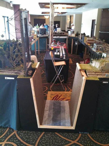
My GTW Trenton & Western Layout is an "around the walls" track plan, which means you either have to crawl under it or build a lift-up section to get in the room.

I'm building a lift-up benchwork section with two Atlas Pratt Truss kits.

I'm trying to make it so you can't easily see the gaps in the benchwork or scenery and not see the hinges at all. Needless to say this makes things more difficult, but I thought I'd share how I've done things so far.

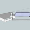
1. I used Google Sketch Up to mock up the concept

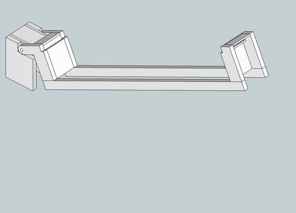
Lift Bridge Module


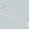
2. This is a view of the main span. There are two of these parallel to each other.

Main Span 1


3. Here's how the span lifts open.

Main Span 2


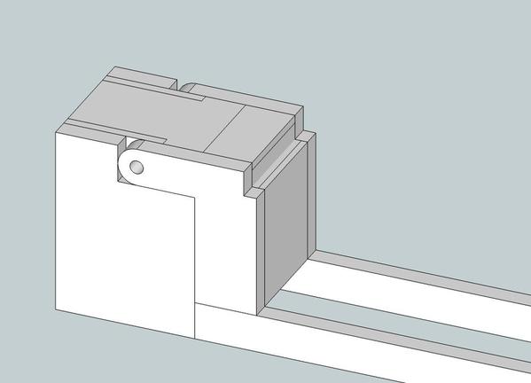
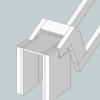
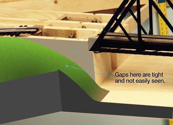
4. A close up of the "seamless" abutment. The vertical seam on the sides will be hidden by a thin sheet of styrene that is painted to look like concrete. The track will need to be back cut at a 45 deg. angle at the seam.

Seamless Bridge Abutment 1


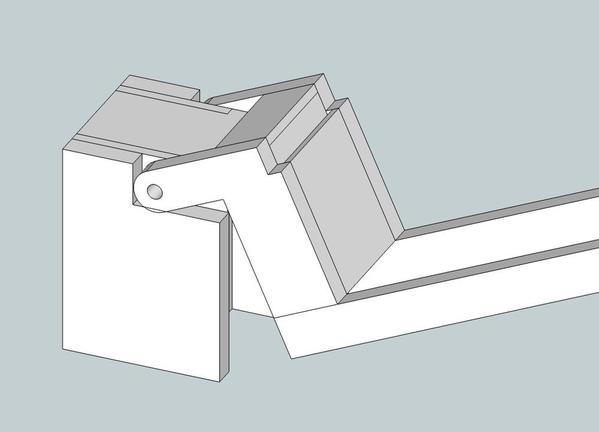
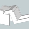
5. Here you can see where the pivot point and the seams are. The top deck seam will be hidden by the track work, both of which will need to be back cut at a 45 deg. angle so it won't bind up. The key to having this work is to keep the pivot point both below and behind the seam.

Seamless Bridge Abutment 2


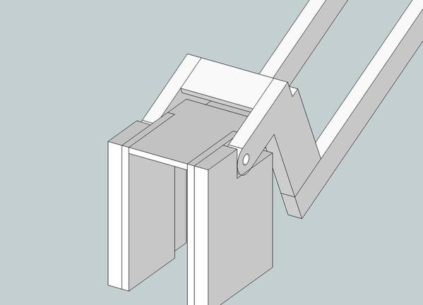
6. A reverse angle of the span opening. 

Seamless Bridge Abutment 3


Here's a few shots of the work in progress:

1. The real thing... FINALLY!  It took all summer for me to test and make things work in "the real world', but planning it all in Sketch Up really saved me lots of hassle!

IMG_3717


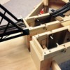
2. A close up of the pivot points (cotter pins and bronze bushings) that serve as "hidden" hinges.

 IMG_3720


3. Lastly, Sam helps me to do a test. The whole thing is a bit heavier than I had hoped, but not difficult to lift at all. The bridge is not attached in this test, so we didn't go the full 90 deg. 


Anyway, that's all I've got for now. Hopefully I can find some time to get back to work on this over the winter! 

Attachments

Images (8)
  • IMG_3717
  • IMG_3720
  • Lift Bridge Module
  • Main Span 1
  • Main Span 2
  • Seamless Bridge Abutment 1
  • Seamless Bridge Abutment 2
  • Seamless Bridge Abutment 3
Videos (1)
Bridge test
Last edited by Rich Melvin
Original Post

Replies sorted oldest to newest

Nice design.

No avoiding the rail angle cut with the hinges where they are. Looks like you could make some relief in the frame behind the lower part of the hinge for some track power cut-off micro-switches.

Don't forget to kill the power back from the bridge enough accommodate the longest passenger train with lighted cars. They will pass the power if it's too short.

Moonman posted:


Don't forget to kill the power back from the bridge enough accommodate the longest passenger train with lighted cars. They will pass the power if it's too short.

Thanks for the tip.

I don't run many passenger trains, but that's something I certainly never thought about. I am designing the power-off  sections on either side of the bridge, but only enough for 3 locomotives.  I'm really not that worried about dropping anything off the layout with the bridge up. The "3 loco" power breaks should do the trick for me.

Nice looking bridge.  We made one for our modular club, we have 1/2" Plexiglas as the base, the bridge is bolted onto that base.  It uses a piano hinge on one side and 1/2" pins and mating sockets to align the bridge when it's down.  A pair of micro-switches interrupts power to the adjacent modules when the bridge is up to avoid "drive-bys".

Lift Bridge ClosedLift Bridge Open

Attachments

Images (2)
  • Lift Bridge Closed
  • Lift Bridge Open
gunrunnerjohn posted:

Nice looking bridge.  We made one for our modular club, we have 1/2" Plexiglas as the base, the bridge is bolted onto that base.  It uses a piano hinge on one side and 1/2" pins and mating sockets to align the bridge when it's down.  A pair of micro-switches interrupts power to the adjacent modules when the bridge is up to avoid "drive-bys".

Nice work Rich & John!  John, I think you mean "drive-offs", right?
Last edited by Rod Stewart

Hi Alan

Everything you mention is what I was trying to solve. The tests I did with track temporarily in place worked great.  I wish I had shot some photos or video of that test!

The key is to have the hinges and the gap in different places with the hinges being above, or in my case, below the tracks. Let me whip up some diagrams tonight and I'll post them so you can see what I mean.

Heavier than I had intended for sure, but not that bad actually.

If I had to do it over again, I know exactly how to cut the weight almost in half. Actually, I considered this a prototype at one point so I could build a lighter one, but my wife said: "Why? This one isn't heavy at all". Being that this is the first time my wife has ever showed interest or given input towards my work, I decided to use it as built.

She's an engineer with an aerospace degree. How am I gonna argue with that?!

loco-dan posted:

...you need a straight section of track on approach to the bridge that is almost as long as your longest car.  Or the car swing will hit the bridge when entering or exiting.

I've checked for that.  The curves are wide enough ( 088 ) that even my Lionel 89' auto racks won't hit anything.

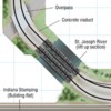
Here's a close up of the bridge area from my track plan:

Close-Up-Bridge-area

Attachments

Images (1)
  • Close-Up-Bridge-area

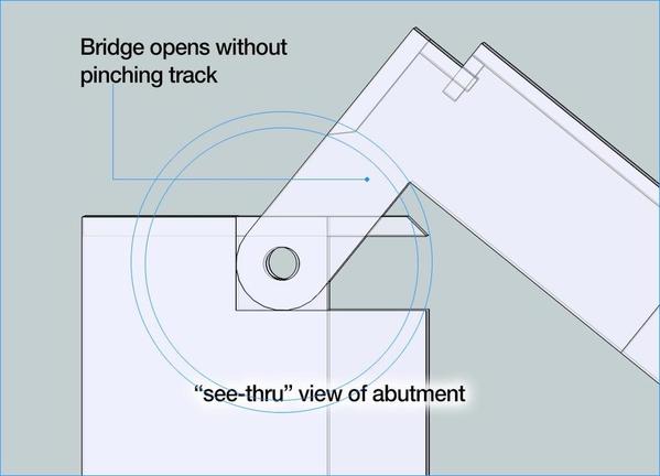
Alan asked about the track gap and the possibility of the track getting pinched or damaged. Here's how it dealt with this.

1. This side view shows the 45º angle of the road bed at the gap (track not shown, but would be directly on top with same bevel as road bed) The gap is roughly "1/16 -ish" wide.

Side-view-w-bevel-1


2. Here, we see the bridge open with the hinges below and behind the beveled gap which allows the bridge to open without pinching anything.

Side-view-w-bevel-2


3. The bridge only opens to a 90º vertical. The track above will not crush the track below.

Side-view-w-bevel-3

Attachments

Images (3)
  • Side-view-w-bevel-1
  • Side-view-w-bevel-2
  • Side-view-w-bevel-3
Last edited by richtrow

Add Reply

Post

OGR Publishing, Inc., 1310 Eastside Centre Ct, Suite 6, Mountain Home, AR 72653
800-980-OGRR (6477)
www.ogaugerr.com

×
×
×
×
Link copied to your clipboard.
×
×