Ken

Love this thread. No comments from me here, looks like you have achieved all you need for FUN. When do you start construction as I cant wait to see a video pf trains running.

Not sure of you ever saw any video of Bob Bartizek's the Pennsylvania and Western, I have attached a link to one of his you-tube videos but for real enjoyment purchase OGR Video #11 30 minutes + is dedicated to this layout. What you are creating is close. 

https://www.youtube.com/watch?v=wO6m0wRSiOo

Steve, thanks for the video, I definitely see some similarities.   It would seem that Rick's layout has broader curves.  Bob has some outstanding scenery!   Interesting that Bob ended up with more operators than he originally thought would be sufficient.   For Rick's layout I would think 7-8 operators would be about all that could be kept busy.   -Ken

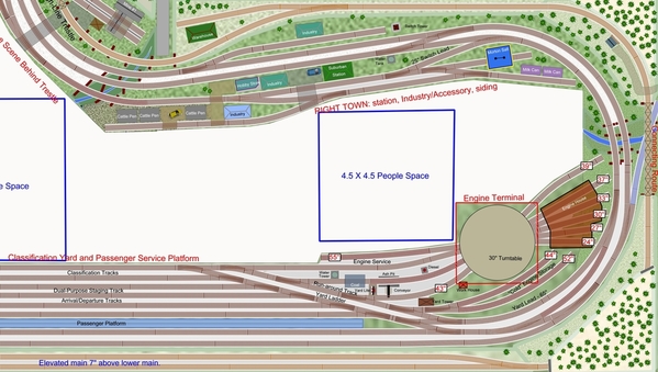
Great work, my only comment is based strictly on my personal preference to be able to run any given train anywhere on the layout. I would take that connecting rail spur on the bottom left and bring that up to meet the elevated track. Why have an interchange with a non-existant railroad when you have a completely separate line to interchange with?

I have to agree with you, METSNO1FAN, it would be nice to have the upper and lower mains connected. Ken and I discussed that, and I decided, against Ken's advice, not to do so. I went with the isolated upper main for the sake of simplicity, and out of a desire to have an upper level mainline. Now that the plan is essentially done, I can see where we might be able to come off the spur above the small town on the left, nearest the breaker box, and down-grade to somewhere along the lower outside main. This would allow access to the spurs on the upper main, which could provide coal loads and lumber, etc. to the lower level. I'd like to hear other opinions on how best to connect the upper and lower mains, if we decide to do so. One thing I don't care for is long sections of elevated track just to make the grade, especially when it makes access to lower level track, switches, and cars difficult.

Rick

To add to the discussion about connecting the upper and lower levels:  the upper level is currently planned for 7" above the main level.  Using the Woodland Scenics approximations used in their risers (i.e. 3% grade is 3 inches over 96 inches (8 feet)), then to make the grade at 3% for 7" we need 18.6 feet of grade.    A run at 2% would require 28 feet, perhaps undoable to fit in.   A run of 4% would require just 14 feet, but I think that 4% is too steep for long trains, but could work for short trains and could be a part of the fun action (dispatching a train able to make the run up the grade).   Depends on what Rick would like - I recommend a grade of around 3%, plus or minus.

Other options could include adding a grade on the double-track main line at 2%, in order to meet a gentle grade coming down from the High Line.   

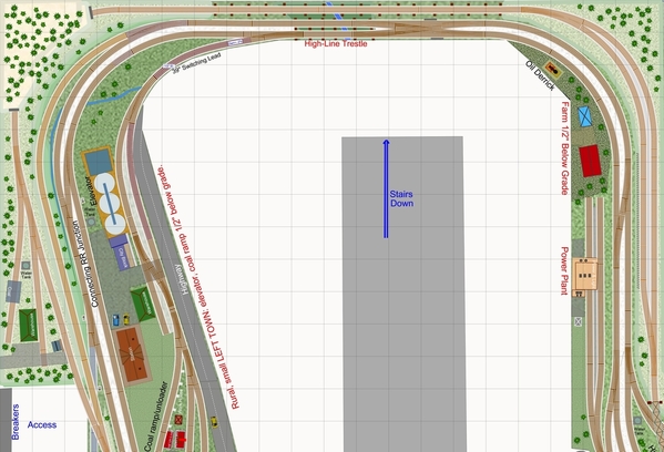
A) I am seeing one place where perhaps this could be done with minimal re-alignment: along the left-hand side as Rick suggested, but instead curving off from the existing High Line in the tunnel in the upper-left corner, and running down to meet the main lines before the lift-out bridges.   3% or so.   Eliminating the current junction and connecting road due to clearance issues with the descending grade.   There may be other alternatives, this alignment just jumped-out at me.  

B) If 4% is acceptable, it might be possible (following Rick's suggestion) to branch off the High-Line near the water pipe and descend toward the top of the diagram, and toward the mains connecting at the curve before the trestle.   This might keep the existing connecting road and junction, which is useful for swapping cars and locos with the train storage shelves.   

C)  Option B, but with with the mainlines rising and falling at 1% or 2% either side of the new junction with the descending grade, so at the junction would be 1 or 2 inches higher than currently, which would then allow the descending grade to be between 3% and 3.5%.   Also changing the grade through the town.


Last edited by Ken-Oscale

Option A will require a good bit of re-alignment, after all, to make it work, but will result in a grade of just under 3%.

It just occurred to me that as this option will block the current connecting track and junction, it would be possible to run a connecting track off the High Line in the same alignment, but at 7" in height. 

Last edited by Ken-Oscale

There is another alternative Option D:  eliminating the passing track on the high line, near the power plant and farm, and replacing this with a track on a grade.   Coming off of the curving trestle at the mine, and descending to connect with the main line near the cross-over beneath the trestle.   This would be at 3.75%.   Less if we allow the mainline to rise up to meet the descending track.   I hate to give up this passing track that allows trains to pass each other on the high-line.

Rick could choose both Options C and D, with a double-cross-over beneath the High-Line Trestle, and have grades running in both directions.   So a train could ascend to the High Line and then descend back to the double-track mains, using the double-cross-over to preserve right-hand-running.

Option E:  Basically what Rick and I looked at earlier:   eliminate the passing and staging track on the High Line at the bottom of the diagram, with a connecting track (running either direction).   If Rick wants to preserve this passing/staging track, the yard could be pulled-out about five inches to allow a grade to connect the High Line and main lines.   Crunching the people space, unfortunately.

It seems that none of the options to far, are without trade-offs of some kind.

Yikes! Another idea Option F:, don't know if it is tough to visualize:  At the bottom of the diagram using the turnouts at BOTH ends of the High-Line passing track to instead begin a descent toward each other.   Where these two tracks meet at 3.5" in height, connect them with a double-slip switch, so that each direction can then continue down to the mainline.   Grade would be about 2.5%.  Would be interesting to see and use!  This alignment could still be used as a passing track on the High-Line, where a train dips down to the double-slip, and then rises back up.      The double-slip switch most likely needs an approach track in all four directions closer to level, for reliable operation, a vertical grade easement of say 1%, which would drive the rest of the grade up to nearly 3%.

Last edited by Ken-Oscale

I am leaning toward this solution for a single connecting grade and junction between the High-Line and the mainlines:

Ricks-HighLineJunction_V10d

This junction design preserves all of the good features worked in so far (passing tracks and the connecting road junction).   The new curved turnout making the connection, is level at 1-1/8" elevation, with grades of about 1.75% on the outside mainline between the new turnout and the cross-overs in either direction.   The slope from the new curved turnout up to the high line is 3.7% - perhaps OK for this operation.  The turnout length is about 2', so that is a level spot of about 2' between grades.   

On the inside main on the parallel curves, I brought the line up to 1/2" in elevation, with grades of about 1.1%, so that the terrain slope continues from the high point above the tunnel down through the three tracks each at a different level, then following the stream to the switching lead serving the town.  The switching lead (now 39" long) descends to -1/2" in the town itself (at about 1.5% grade), for a pleasing and convincing look to the scene.

Jan, there is already a mine on the High Line, near the connecting road track.   Rather than mining coal, I thought that perhaps the railroad would benefit from some diversity, with some other ore - perhaps copper.   Then in the far right town, a small smelter operation could be added to receive the ore (where the Morton's Salt tower is currently).   Giving a reason to move trains from the high line to the main level.

With just a single direction connection, and no way to turn trains on the High Line, trains will have to back down the grade at some point, or use one of the passing tracks to run a locomotive around the train, so that the engine descends at the head of the train.   Adding Option D will solve this problem, and it would seem to be possible to preserve the passing track, by angling and pulling the mainlines toward the aisle, at the expense of the farm, so as to stay within the current benchwork limitations without compressing the aisle.

Attachments

Images (1)
  • Ricks-HighLineJunction_V10d
Last edited by Ken-Oscale

Looks like a good solution, and the fact that the engine will have to run around the train should be no problem. Very prototypical.  However, if Rick intends to run steam locomotives it would, if I'm understanding this correctly, require him to attach a coupler to the front of the steam locomotive.  Hmm.....Maybe a scale kadee like used on the Black Diamond that would also grab a regular coupler.  I think that this animal exists.  Of course I could just be delirious, I do need coffee.

You might enjoy a short look at a pre-civil war iron furnace, used during the Confederacy, and destroyed by the Union, not far from where I live, not too far from a CSX main line.   Just the furnace remains, not sure what buildings would have been constructed.   This could be an idea for an industry to process iron ore from the High Line mine (depending on the era Rick wants to model of course, perhaps updated for a more modern industry).

Cooper Furnace Historical Site

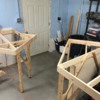
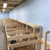
Finally getting started on the layout that the very talented Ken Hoganson designed for me! Thought I'd start adding progress updates to this thread as things... progress.

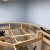
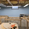
Due to budgetary constraints I decided not to undergo any major basement finishing, and get rolling on the benchwork etc. The walls will have a simple backdrop installed to improve appearance, the floor will get a cushy, interlocking, foam tile type covering, and the studded walls around the central staircase will also be covered for a more finished look. Lighting is nice and bright with LED shop lights  providing illumination. The attached photos follow the benchwork as it proceeds around the perimeter of the basement. There are no duck-unders needed as the stairs come down away from the walls. The open area in the benchwork, near pictured the door, will be home to three bridges that will lift out for access to that exterior door on the rare occasion we need to use it. The long stretch of brenchwork with the elevated line will be widened to provide more layout space as required.

The last photo shows my roadbed and track- 1/2" plywood, 1/2" homasote under the track only, with Woodland Scenics foam roadbed, Gargraves track, and Ross switches. Using only adhesive caulk to attach roadbed and track- no screws. Preliminary tests have shown this to be very quiet and stable.

I have a long way to go, but as an old friend once told me, "Just get started, do it before you get too old and can't". There was a much longer, philosophical conversation revolving around that subject, but that was sound advice to someone who tends to have "paralysis by overanalysis". He has since passed on, but his words still inspire me. This layout is dedicated to him. Rest in peace, CSM Paul Rausch, you are missed.

Rick

Attachments

Images (14)
  • A: Future "industrial" area
  • B: Trestles and mine scene
  • C: Trestles and mine scene
  • D: Dramatic bridges and mountains will go here, at bottom of entry stairs.
  • E: Wide section for small town, with space behind for electrical access and storage
  • F: Wide section with space behind for electrical access and storage
  • G: Location of lift out bridges for access to exterior door and storage
  • H: Location of lift out bridges for access to exterior door and storage
  • I: Lower level here will be widened by ~1ft to accommodate yard and passenger tracks
  • J: Lower level here will be widened by ~1ft to accommodate yard and passenger tracks
  • K: Upper level curve at end of yard area
  • L: Upper level curve at end of yard area
  • M: There will be a river here, with bridges connecting yard area to industrial area
  • N: Example of roadbed
Last edited by ricka1

I know you decided not to finish the basement, but you will get a LOT of dust filtering down from those exposed insulation batts up above.  Some drywall (it can be the 3/8" stuff, easier to lift above) screwed to the joists will make you a lot happier later.

Nice clean benchwork installation by the way! 

ricka1 posted:

Well, I'm the guy that asked Ken to design this layout, and I have to say, I am really happy with the result! The purpose of the layout, as Ken stated, was to have fun, run some trains with my friends, and maybe do some "operations". I've "operated" on some great model railroads, many that have graced the pages of Great Model Railroads, and Model Railroad Planning, etc. I've used a timetable and train orders to move my train safely along the mainlines of some beautifully created miniature worlds. That was fun, but not really what I was looking for in my model railroad. I didn't need something that was too prototypical, but wanted something that still allowed for some switching of cars, and breaking down and making up of trains in the yard. I also wanted a layout that would allow for some nice scenery, and fun creating scenes for the trains to run through. I wanted something rooted more in postwar hi-rail, with a nod to more current practice. Let's face it, there are many times, I think most of us just want to watch the trains run. I think Ken achieved exactly what I was looking for!

I really appreciate the great feedback from all of you. I think it's resulted in a few additions and alterations I will probably incorporate. I really like the idea of having interchange traffic, and Ken's changes around the mine are very nice. I'm curious about making the yard partially stub-ended. Making two arrival and departure tracks, and three stub-ended classification tracks would increase capacity and versatility. I don't think the yard lead needs to be any longer- it's very rare that you'll see a switcher pulling a full yard track out at once, while building a train for departure. I'm attaching a pic of the yard design that inspired me to include such a feature. It's from one of John Armstrong's books.

After construction of a few smaller layouts, one of which occupied the 12x20 area in the lower right of Ken's plan, I'm beginning the process of  preparing the the basement for this new empire. It'll be some time before I get to the point where I'll be building benchwork, laying track, and creating scenery. I will be sure to document the progress and share with you all. I'm also sure I'll need some advice along the way, as this will be my most ambitious, and likely my "lifetime" layout.

Thanks again for all the great feedback! 

Hello Rick,

I think it is an absolutely beautiful layout and Ken has done a beautiful job with your requirements.

I know I'm a bit late, but unless I've misunderstood, I think there's a more optimal incline location. At the far right of the yard, could the blue connecting track curve around behind the bridge, up around the corner, and then connect by the passing siding to the right of the stairs, going behind the mine. Aside from moving the high line out from the walls along the rightmost and Righton walls, I don't think it'd require too much modifications. May be wrong though.

Add Reply

Post
The Track Planning and Layout Design Forum is sponsored by

AN OGR FORUM CHARTER SPONSOR

OGR Publishing, Inc., 1310 Eastside Centre Ct, Suite 6, Mountain Home, AR 72653
800-980-OGRR (6477)
www.ogaugerr.com

×
×
×
×
Link copied to your clipboard.
×
×