Hi,

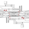
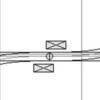
I'm having issues wiring these DS's. I have 4 Double Slips with 2 of them in different spots of the 3 loop layout. I want to wire these for the non-derailing feature to work from all sides without using relays. Wondering if this is at all possible? I can get slip number 1 to work correctly but the 2nd slip will work from 2 sides but the other ones will not. Any tips on how to wire these correctly?? I followed the directions that came with the switches but still having issues. Looked on you tube and ross web site but not much help. This is my 3 rd layout so I'm somewhat fimilar with this stuff but my first time with the DS's.

Thanks in advance!

DanRoss DS Sw 1 of 2Ross DS 2 of 2

Attachments

Images (2)
  • Ross DS Sw 1 of 2
  • Ross DS 2 of 2
Original Post

Replies sorted oldest to newest

Still need some help with this? I have on of these DS on my layout, but have not wired for derailing yet. 

As normal, you need insulated rail sections, so the the DS, you need 4 isolated rail sections, one for each "arm" of the DS. I have added in red the area where you need the 4 isolated rail sections in the DS diagram from Ross. To each isolated rail section, you need to solder a wire that will reach either of the two DZ2500 switch machines of the DS.

dblslipadvanced derail

I don't have power to my DS at the moment, so you will need to do a bit of experimenting on your own. You only use the Green and Yellow wires of the DZ2500 switch machines. The experimenting is that I can't tell you which wire from what switch machine you need to connect to a particular isolated rail section. First, pick a leg you want the derail to work on. Next, determine which DZ2500 needs to be energized to prevent the derailment. Now you at least know which DZ2500 to hook up to the isolated rail in the leg you have started with. Try the green wire, put the switch in the position to derail, move a car by hand into the isolated rail, and see if the switch changes to prevent a derail. If not, disconnect the green, and connect the yellow, then repeat the move car by hand to test.

You can email me at my email address in my profile if you need some more help.


Attachments

Images (1)
  • dblslipadvanced derail

Took a look at the wiring schemes of the breakout board to DZ-2500. Also looked at DZ-2500 to DZ-1008. Looks like the DZ-1008 would be spliced in between the Breakout board and the DZ-2500 connecting to the Red Black Green and Yellow wires as per Z-stuff wiring diagram for DZ-1008 to DZ-2500. Not sure why you want to do this unless to wire to block signals maybe, or power routing? The breakout board has connections for non-derailing feature. This is the first I have looked in to this but unless there is a power restriction on the breakout board I would think one board could be wired to control two opposing switches. Placement of the derailing wires for the out position may be a little tricky but since both opposing switches will be thrown in the out position at the same time. It would possibly not be needed at all.

You will have to download PDF's from Lionel and Z-stuff for the wiring diagrams. I haven't figured out how to link them here.

I never used the DZ-2500's to TMCC or Legacy. Z-stuff had the 2001A data wire drive. At one time there was a lot of discussion of having the switches chained together with the data wire driver and if one switch in the chain failed I thought all of them had to be programmed again. This was enough to stick to push button control at the control panel. It was quit intensive to wire but when a DZ-2500 or DZ-1000 fail all we have to do was wire in a new one. No programming . Things have evolved a lot further since then.

@Forest posted:

I never used the DZ-2500's to TMCC or Legacy. Z-stuff had the 2001A data wire drive. At one time there was a lot of discussion of having the switches chained together with the data wire driver and if one switch in the chain failed I thought all of them had to be programmed again. This was enough to stick to push button control at the control panel. It was quit intensive to wire but when a DZ-2500 or DZ-1000 fail all we have to do was wire in a new one. No programming . Things have evolved a lot further since then.

I don't think you have to reprogram everything for a failure, that must be some of the older stuff.

PLEASE, look at the DS wiring diagram carefully. The switch motor which is thrown for non-derailing, on either side,  will not be the same switch that will cuts power  to the respective track sections 1,2, and 3,4 ( if you are using relays). Depending on the original route, the other switch may have to be thrown also. I use CAB2 routes to program my DS; left to right 1(A-A), 2(B-B), 3(A-B), 4(B-A). I have two switches attached to the B legs which may also throw for routes 2,3, and 4.

Last edited by WinstonB

I see that's the way it's drawn up, but I see major issues in that arrangement.  Convince me I'm wrong...

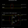
Refer to the diagram below, you'll probably have to click on it to expand it.

Let's say I'm entering on the left at A and exiting on the right at D, and the #1 rail on the left has been switched to center track power.  All is well and I transition the switch.

Now I enter on the left at A and switch the right to exit at C, the #2 rail on the left is now switched to center track power.  All is NOT well, and I have a direct short across track power and promptly trip the breaker!

Double-Slip Switch Power Switching

Updated picture to show switch machine link to movable rails.

Sorry, but I don't see this working, if I'm wrong, what am I missing?

Attachments

Images (1)
  • Double-Slip Switch Power Switching
Last edited by gunrunnerjohn

John

I think about it as if it’s 2 separate switches, split down the middle.  Lets say switch machine 1 changes route A/B and switch machine 2 changes route C/D.  With your scenario, you are only changing switch machine 2 and therefore only changing power to rails 3 and 4. Since you are going though route A both times, you are not touching switch machine 1, therefore not changing power on rails 1 and 2.

Last edited by Tanner111
@Tanner111 posted:

John

I think about it as if it’s 2 separate switches, split down the middle.  Lets say switch machine 1 changes from route A/B and switch machine 2 changes from route C/D.  With your scenario, you are only changing switch machine 2 and therefore only changing power to rails 3 and 4. Since you are going though route A both times, you are not touching switch machine 1, therefore not changing power on rails 1 and 2.

Jim, that's not the way that it's written up by Ross or described by WinstonB below!  I've quoted his message and attached the Ross DSS wiring diagram PDF as well.  You can clearly see they have the switch machine controlling the right half switching the powered rails on the left half, and vice-versa.  IMO, this is clearly wrong, and I can't see how it would work.

I'm with you, IMO it should be treated exactly as two switches, that's the way I'm using it, and I'm going to wire it that way as well.  I can't see any way that it could work with the wiring proposed in the Ross DSS document or by WinstonB.  I will be questioning Steve at Ross on Monday about that wiring diagram as well.

I updated my original picture to illustrate which switch machine is switching which side with the dotted arrows.

@WinstonB posted:

PLEASE, look at the DS wiring diagram carefully. The switch motor which is thrown for non-derailing, on either side,  will not be the same switch that will cuts power  to the respective track sections 1,2, and 3,4 ( if you are using relays). Depending on the original route, the other switch may have to be thrown also. I use CAB2 routes to program my DS; left to right 1(A-A), 2(B-B), 3(A-B), 4(B-A). I have two switches attached to the B legs which may also throw for routes 2,3, and 4.

Double Slip Switch Wiring.pdf

Attachments

Last edited by gunrunnerjohn

Jim, that's not the way that it's written up by Ross or described by WinstonB below!  I've quoted his message and attached the Ross DSS wiring diagram PDF as well.  You can clearly see they have the switch machine controlling the right half switching the powered rails on the left half, and vice-versa.  IMO, this is clearly wrong, and I can't see how it would work.

I'm with you, IMO it should be treated exactly as two switches, that's the way I'm using it, and I'm going to wire it that way as well.  I can't see any way that it could work with the wiring proposed in the Ross DSS document or by WinstonB.  I will be questioning Steve at Ross on Monday about that wiring diagram as well.

I updated my original picture to illustrate which switch machine is switching which side with the dotted arrows.

Double Slip Switch Wiring.pdf

John

Now I see what you’re saying.  I am curious what Steve says.

I believe Ross' DS diagram is correct.  The DS is my next switch to install, and a few months ago I set it up on my workbench to see how it worked.  Sorry it took me a while to put my chicken scratch drawings into PowerPoint, but here it is.

The left side of the chart shows which lead rails need to be energized for the trains to make it through the switch.

The right side of the chart shows which lead rails are energized for DZ-2500 switch position.  This assumes all 6 wires from the DZ-2500 are connected to the breakout board and the green and yellow wires of the DZ-1008 are connected to any of the breakout board's green and yellow inputs.

For DZ-2500 'X', green LED has switch machine energizing the white wire (#1), red for gray (#2).  For 'Y', green LED has switch machine energizing the white wire (#4), red for gray (#3). 

DS_lead_rail_wiring

At least I hope it works this way or I'll have a couple of burned out DZ-2500s.

Attachments

Images (1)
  • DS_lead_rail_wiring

In my mind the DSS is just two switches back to back, so if I treat them that way, it's not problem to see how the rail switching works, you do it just like you would on any other switch that needed power to those rails.

In your graphic, you have the rails to be energized correct, but I question how you get there, because using the Ross diagram, I don't believe you can.  I see no way that if I'm coming in the A track on the left side and controlling the power to the dead track sections from the right side can possibly work.  For one exit path, I'll have a direct short every time!  However, if I control the relay from the same side, it's no problem to make it work.

Go back to my drawing and explain how you make it work with the Ross wiring.

It makes no sense to me and has to be a mistake.  There's no way that could work!

I wired my DS just as the diagram shows from Ross with relays. However, I did not wire for non- derailing.  I set the desired CAB2 routes before a train enters the DS. CAPPilot’s operation as described is the setup I have. You observation is correct that’s why all my routes are set by me manually. My post was for those attempting to wire for non-derailing operations, using the Ross setup,  to point out the issue with the various powered sections labeled 1,2,3 and 4.

Last edited by WinstonB

John,  All I can say is it worked for me back them.  I hope to have the DS in by next weekend so we will see.

I also played with the non-derailing.  I think it will work but you will not have a choice as to which way it goes out of the switch.  You have 4 ways into the switch, but each of those 4 ways has two ways out depending on how the other switch machine is set.  If it goes onto a track with a train on it you might get more damage than if you had just let it derail.  I'm going to solder the derail wires onto the switch before installation, but not sure I will use them.

Last edited by CAPPilot

I have played with the switches and the paths through the switches.  I'm not sure what issues you foresee using the non-derailing, but I'm not anticipating any issues there, and my testing by sky-wiring the switch and running my battery powered locomotive through the two DS switches worked just fine.  Remember, non-derailing only pertains to the entry side, the exit side is set to whatever route you desire (or maybe to one you don't desire!).  However, there is only one potential trigger for the non-derailing if you wire it right, when you exit the DSS, the non-derailing logic should be such that the switch machine is already in the position that is being called for by the non-derailing rail connection, hence no switch movement.

As for the DZ-1008 relay wiring, I'm still not seeing how wiring the relays for the DSS like the Ross diagram can possibly work.  I'm sure not going to wire them that way until someone convinces me with solid logic that it will.  In two or three sentences I explained why it can't possibly work, and all the postings since have not refuted the facts as I presented them.  I'm waiting to be proven wrong, but I just don't see it yet.  That being said, it's hard to believe those diagrams from Ross have been around as long as they have and nobody has had a problem, that I don't understand!

The phone lines are open and operators are standing by!

Last edited by gunrunnerjohn

I see that's the way it's drawn up, but I see major issues in that arrangement.  Convince me I'm wrong...

Refer to the diagram below, you'll probably have to click on it to expand it.

Let's say I'm entering on the left at A and exiting on the right at D, and the #1 rail on the left has been switched to center track power.  All is well and I transition the switch.

Now I enter on the left at A and switch the right to exit at C, the #2 rail on the left is now switched to center track power.  All is NOT well, and I have a direct short across track power and promptly trip the breaker!

Double-Slip Switch Power Switching

Updated picture to show switch machine link to movable rails.

Sorry, but I don't see this working, if I'm wrong, what am I missing?

Your logic here would be correct. I’m not home to check the color as wired on the DZ 1008, but here is my setup. When both Dz 2500s light green, the route is A-A, and the Dz1008s wire for NC powers track section 1 and 4. When both DZ 2500 lights are red, the route is B-B, and the DZ1008s wired NO powers track sections 2 and 3.
If the route was both DZ2500 lights green for A-A and I wanted A-B, or A-C on your diagram, it’s the lower/bottom  switch I would change to red. Track section 1 would remained powered and the DZ1008 for the bottom switch would power NO track section 3.

For a B-A route, the upper/ top Dz2500 would switch to red and its Dz 1008 NO would power track section 2. The lower/bottom DZ2500 would remain green and its Dz1008 NC would power track section 4.

@Tanner111 posted:

I think if I had one of these I would wire them as 2 separate switches, including non derailing. I don’t see a benefit of going any further than that. I don’t want the train to derail going into the switch. If it leaves the switch on the wrong leg that’s my fault and I need to pay attention.

That's my current plan, that's the only way I see it working properly.

I agree, there's nothing that the switch or relay can do to fix it if I screw up and have the exit path set wrong.  However, as long as the relays and switches to their job it will only collide with the oncoming train, but it won't derail or short out the track power!   Come to think of it, if it's going out the wrong path, maybe I want it to trip the breaker.

@WinstonB posted:

Your logic here would be correct. I’m not home to check the color as wired on the DZ 1008, but here is my setup. When both Dz 2500s light green, the route is A-A, and the Dz1008s wire for NC powers track section 1 and 4. When both DZ 2500 lights are red, the route is B-B, and the DZ1008s wired NO powers track sections 2 and 3.
If the route was both DZ2500 lights green for A-A and I wanted A-B, or A-C on your diagram, it’s the lower/bottom  switch I would change to red. Track section 1 would remained powered and the DZ1008 for the bottom switch would power NO track section 3.

For a B-A route, the upper/ top Dz2500 would switch to red and its Dz 1008 NO would power track section 2. The lower/bottom DZ2500 would remain green and its Dz1008 NC would power track section 4.

Yep, that's my thinking.  I'm glad I spent a little more time looking at this, I was going to go mount the relay and connect it, but following that diagram would have led to disappointment.   I'm still interested in what Scott will have to say about the diagram.

@WinstonB posted:

I did mine 2 1/2 years ago and followed the diagram when the Dz2500 and Lionel LCS with control board  was new to me. Now I have boxes blocking my access. At some point I’ll switch the 1,2 and the 3,4 wires to make it a simple back- to- back switch. Plus, with a PSX-1AC, I had some safety margin.

I'm not sure why you are going to switch the wires if you have been running your layout for 2+ years the way it is?  Does your switch work as advertised wired per RCS' diagram?

Hoping to start laying track and wiring the layout next spring.  I'm a bit anxious about wiring the layout. I find this thread and the one on troubleshooting the wiring for the DZ2500 non de-railing to be really interesting. I'm copying and saving for future reference.  Thanks guys. It's fun to watch people who know their stuff. Really cool. Glad you guys are around.  and thanks for inserting the pics - they help a lot.    

Sorry that this is a long post, but a lot to cover.

I have a Ross Doubleslip (DS) switch w/DZ2500s installed on my layout, but have no DZ1008s for roller gap reduction, nor any derail protection wired. So the following is my attempt to understand and draw wiring needed to add the DZ1008s and derail prevention. I will be wiring based on this and debug as I go along. It is correct based on how I have used the DS on my layout, experience with the DZ2500s on my layout, and research into docs from Ross Custom Switches and Z-Stuff for Trains.

First - understanding the DS. At first look, you may believe the DS is just two back to back switches with the area the switches are joined is compressed as much as possible.
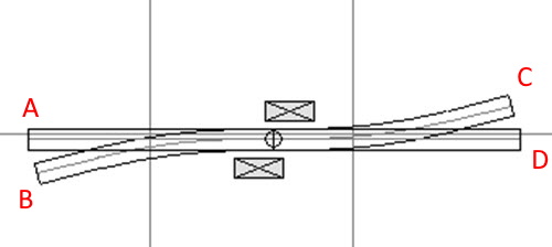
DS Back to Back

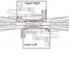
So if the switches are set for path A to D, then you want to change to path A to C, you would throw the switch machine associated with the right hand switch. However, the DS mechanics are completely different than two back to back switches. Below is a drawing from Ross that @gunrunnerjohn first, and I second, have added annotations to. This drawing will my reference for the remainder of my discussion, and refer to it as Overview.

DS annotated

For discussion purposes, the A, B, C, & D are used to define a path through the switch, like A to D (enter A, exit D). The Upper Right (UR) box contains the DZ2500/DZ1008 combination, the DZ25000 controlling the points of the Right half of the DS, the DZ1008 connected to the DZ2500. The Lower Left (LL) box contains the DZ2500/DZ1008 combination, the DZ2500 controlling the points of the Left half of the DS, the DZ1008 connected to the DZ2500. The Iso A, Iso B, Iso C, and Iso D are isolated outer rail sections for derail prevention use.

So, DS operation. There are four possible paths through the DS, and below are four pics, each pic shows one path, and I highlighted with green lines how the wheels will track through the points of the switch. Since the switch symmetrical, i.e. Path A to D is the same switch setting as Path D to A, I have written as entering from left, exiting to right.

Path A to D - this path I will use my main state, as it is the mainline on my layout
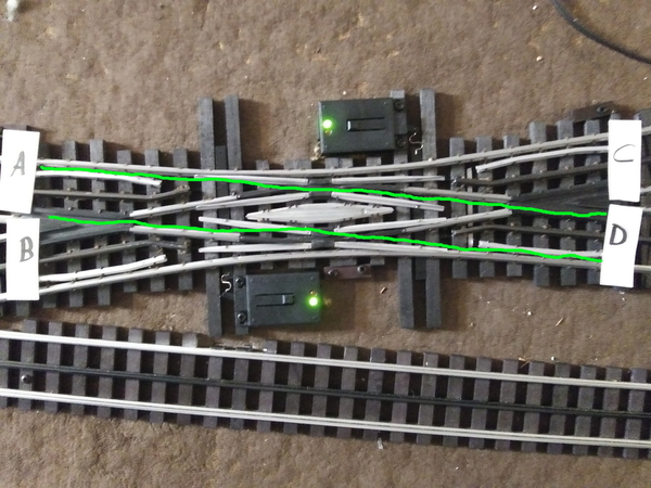
DS A to D

Path A to C

DS A to C

Path B to D

DS B to D

Path B to C

DS B to C

I pushed a car through for each path to verify operation. As you examine the pics for yourself, notice the DZ2000 LEDs indicating to you the DZ2500 position. Notice that the difference between Path A to D DS setting and Path A to C setting, only the LL DZ25000 changed. This is the critical operational characteristic you have to convince yourself about.

Further notice that UR is changed when you want to enter from B instead of A, and the LL again controls if B will exit D or C. I have an electrical engineering background, so I made the following electrical analogy, showing relay contacts in place of the points. I included the DZ1008 contacts, wired to match the Overview diagram. The red vertical lines are showing how the contacts are ganged, and controlled by its associated DZ2500. The Analogy shows Patch A to D being set in the DS.
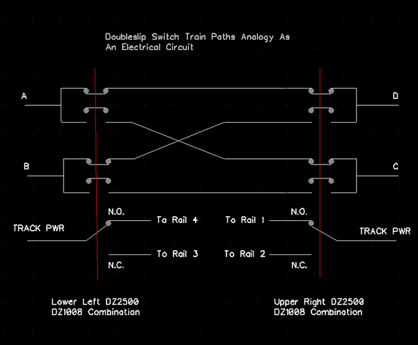
DS electrical analogy

To change from Path A to D shown above, you throw the Lower Left (LL) DZ2500, which makes all the contacts on the left move downward, connecting A to C, and the DZ1008 from N.O. to N.C. - the DZ1008 switching the hot rail from Rail 4 to Rail 3 (Overview drawing) for roller gap reduction.

Next, I have to replace the DZ1000/DZ1002 controller/DZ1008 with the DZ2500/DZ2502 controller/DZ1008. So I came up with this wiring diagram, which is straight forward save for one connection, circled in red, I will deal with a bit later. First, the Wiring diagram.

DS DZ2500 Wiring

Whether you use the CSM2 breakout board or not, Red wires to Switch Machine power rail, Black wires to Ground rail (remember that for DZ2500 derail prevention to work correctly, the DZ2500 ground must be connected to track ground to create a Common Ground), white wire from DZ2502 controller to DZ2500 white wire, and the DZ1008 Common (C) to track power, Normally Open (N.O.) and Normally Closed (N.C.) to the DS rails in the Overview diagram.

So now we come down to the DZ1008 green wire that activates the relay in the DZ1008 when +5 is applied to the green wire. The DZ1008 was constructed to directly attached electrically when you mechanically connect the DZ1008 to the DZ1000 - which is what the Overview depicts, and is why you see no wires between the DZ1008 and DZ1000. From the Overview we see the DZ1008 white wire is connected to Rail 4, which we want to have track power for Path A to D. The DZ1008 white wire is the N.O. output, we need the DZ1008 relay activated for track power on white wire, thus we need +5 applied to DZ1008 green wire. So we need to determine which DZ2500 wire to connect to the DZ1008 green wire. The DZ2500 has two wires, a green wire and a yellow wire, that are used to implement derail prevention and indicate which way the DZ2500 is thrown. So refer back to the Path A to D pic and notice the position of the arm on the DZ2500, it is thrown to the right, when viewing as in my drawing below that I created as green/yellow wire cheat sheet.

DZ2500 Derail Operation Characteristics

The above drawing depicts what happens when you temporarily apply a ground - like isolated outer rail shorted to other outer rail by train. We need a ground on the DZ2500 green wire to get the switch with the arm to the right. Once the DZ2500 green wire ground is removed, the DZ2500 green wire remains at a low voltage level, about 1VDC on your meter. The DZ2500 yellow wire will be outputting +5VDC, what we need to get the relay to be activated - so DZ2500 yellow wire needs to be connected to the DZ1008 green wire to match operation in Overview. If you are using the CSM2 breakout board, connect the DZ1008 green wire to the yellow terminal of the 8 pin connector, not the Thru terminal. For completeness - as you would suspect, temporary ground on yellow wire forces arm to left, and yellow wire will be +1VDC and the green wire will be +5VDC. The +1VDC is really not DC, but is a pulse train - this characteristic is not important to our application. One last thing, which LED is lit on the DZ2500 has no fixed relation to the state of the yellow or green wires. This disassociation allows mounting the DZ2500 in different places but getting the LED state the way we want. The DZ2500 arm position is fixed to the yellow and green wires as I depicted in the above drawing.

So the last is derail prevention. From what we have learned, the UR controls which roller gap reduction rail is energized on the Left half of the DS. Also, regardless as to how the LL has the left DS points set, we will not derail as we enter A. What is of concern is, if we enter A, the UR has to be set correctly for A to D (or C) passage, otherwise we would short the energized roller gap rail in the A entry path, and derail when the train encounters the right half points if they are set to enter from B. This means we have to get the UR switch machine to be thrown "right", meaning the UR DZ2500 green wire must be connected to Iso A. Logically, this leaves the UR DZ2500 yellow wire to be connected to ISO B. Again, since the DS is symmetrical, Iso D goes to LL DZ2500 green wire, and Iso C goes to LL DZ2500 yellow wire. My wiring below

DS Derail Prevention

Attachments

Images (10)
  • DS Back to Back
  • DS annotated
  • DS A to D
  • DS A to C
  • DS B to D
  • DS B to C
  • DS electrical analogy
  • DS DZ2500 Wiring
  • DZ2500 Derail Operation Characteristics
  • DS Derail Prevention
Last edited by MED

I wired mine as two back to back switches with two DZ-2500C machines along with the two DZ-1008 being used to switch power to rails 1-4 depending on the direction of each switch. So each switch with its corresponding DZ-1008 flips the power on/off to two(2) of these rails.

The ross diagram for DZ-1000s was confusing when using the DZ-2500Cs.

As far as non-derailing I used the yellow and green wires of each DZ-2500C wired to the inner short rails on each end of the side that the DZ-2550C was controling.

Last edited by AlanRail

Well, I powered up my DS switches by sky-wiring power to them as I don't have switch wiring completed.  However, I'm slowly coming around to thinking the Ross diagram is actually right after all!  It turns out, I has a misconception of how the path through the switch works.  It's not quite just like two switches back to back, and it turns out it looks like the DZ1008 relay actually does switch the opposite side rails for proper operation.  I haven't actually wired one up to fully test this, but after running my battery powered locomotive through the switch and testing all the various paths, I realize that there's a bit more to the DSS than I imagined.  If it were logically two switches back to back, I could simply switch the right hand side to change the route of the locomotive entering on the left hand side.  However, that doesn't always work as you expect!

In the next few days I hope to have all the switches wired, then I'll be able to test with power my assumptions and I'll post my results.

Well, after some trial and error, I've come up with the following diagram for my Ross Double Slip.  I connected everything on the bench and it works, so I made this diagram so I can duplicate it when I install it this weekend.  If you think about how this switch works, it actually makes sense.

Ross_DS_Wiring

However, unless you actually have this switch to look at, the diagram will be hard to follow.  The big difference with this switch from a standard switch is each side has 4 points, not two.  That is 8 points total.  The result is a train does not derail going into the switch, no matter which leg it enters on or how the DZ-2500s are set.  It derails as it exits if not set correctly.

That means the #2 DZ-2500 on the left in the diagram gets its non-derail and alternating power wires to the leads from the trackage on the right side, and the opposite for the right #1 DZ-2500.  To make it work and keep my wiring colors consistent, the green and yellow wires from the DZ-2500 are connected to the opposite colors on the breakout board.

The wiring to the lead rails is from the switch diagram from Ross (as shown in above posts), so no change there from earlier discussions.  I had to play with it a while to understand how that setup worked.

The issue was the non-derailing function.  I almost gave up trying to make it work because there really are two non-derailing actions when a train goes through the switch; once when it enters and once when it exists.  I was worried that when it exited the non-derailing function would now derail the train.  Well, it turns out with this wiring setup the non-derailing function on exit does not change the DZ-2500s position, no mater how the train exits.

You can also arrange the DZ-2502 controllers so that the LEDs line up to help show switch position.

I'll have it installed soon to see if I got it right.  In the meantime, go ahead and stare at the diagram for a few hours and it will start to make sense.

Attachments

Images (2)
  • Ross_DS_Wiring
  • Ross_DS_Wiring
Last edited by CAPPilot

I'm staring at your diagram now.   I have two of them to look at, so no problem.  I also came to the realization that they're not like two switches back-to-back.

I still have one question.  Since you have two exit possibilities, what determines which route out you take?

What does A-A is main line mean?  There is only one A.

One modification I'll make is to use my improved relay to switch the common and hot rails.

Last edited by gunrunnerjohn

I still have one question.  Since you have two exit possibilities, what determines which route out you take?

What does A-A is main line mean?  There is only one A.

One modification I'll make is to use my improved relay to switch the common and hot rails.

Thanks for noticing the lettering error.  I made a last second change from A-A to A-B, and B-B to C-D.  Didn't catch all the letters that needed changing.

The train will exit the direction the switch was previously set.    For example, if the switch is set up for A to B, and a train comes in from C, the non derail will set the switch to C-B.  If the switch is set up for A-D and the train is coming from C, the non derail will set the switch to C-D.  My concern was the non derail wires on B and D, the exit routes, would mess things up when the train hits them but they don't, at least not in my tests.

Last edited by CAPPilot

I was doing a search for the RCS 270 DSS and hit on this thread from 2021, among others. Lots of really good information here. My question is CAPPilot, how did this work for you after installation? Is the hookup diagram you presented 5 posts up the final as-built version? If not can you provide a final version the way you have it wired on your layout please?

MED your explanation of the wiring and switching logic is well detailed and excellently presented. Easy to follow. How does it jive with CAPPilot's hookup drawing referenced above?

Gunrunnerjohn, did you get yours wired up and operating as you intended? Do you have any additional comments or suggestions to add regarding hookup changes?

I am not familiar with the Lionel breakout boards that CAPPIlot used, or even what they are intended to be used for. Is there any information around that shows the onboard inter-connections? I would prefer to do this using a couple of European style multi-terminal strips, unless there is some magic on the breakout board that can't be duplicated.

Thanks for any help! Rod

If you haven't bought the DSS, I suggest going a different way.  Mine have been nothing but trouble and as soon as I get some time, they're getting ripped out!

Wow; not the response I was expecting, but appreciated nonetheless. Do you care to elaborate; are the troubles mostly at low speed, high speed, straight-thru path, curved, smaller or larger engines, rolling stock, etc?

I see that some folks use one of the straight-thru paths in main lines, and I just wonder how these work with engines traversing at speed?

Anyone else care to add their operational experiences with these guys?

Thanks, Rod

Last edited by Rod Stewart

My problems are multiple.  The biggest issue is engines and rolling stock occasionally short to one of the many moving parts, even though I've run through and dressed them up as much as possible.  The most troublesome routes are when you're diverging, but the straight routes aren't perfect.  I've added the relays to promote reliable transition, but that increases the issues of shorts crossing them.  Note that there's no derailment, just a breaker trips.  As I've localized a specific location where shorts sometime occur and put some tape on it, it seems to appear elsewhere.  Oddly, some locomotives and rolling stock have no problem, but a bunch do.  I'd blame it on the locomotives and/or rolling stock except they run everywhere else, including our modular club layout.  If you can run on something cobbled together with C-Clamps, you should be able to run on a laser leveled platform!

It doesn't help that the unreliable DZ-2500 switch machines don't always complete their throw and the DSS picks a wheel and derails things, that's just icing on the cake.

They will be gone as soon as I get the time to rework that area of the layout!

I have the Ross DSS. I plan to add a second. Currently I have no switch machines or ground throws attached. I flip them by hand and they stay put. I would have to pull it up to tell you how it's wired because I wired it quite a while ago. I haven't added relays (although I have them in case I need them).

My 0-6-0T has a super short wheel base and stalls out at low speeds. My 4-4-2 Atlantic will also stall at low speeds. The 0-6-0T is a yard locomotive anyway so I'm considering permanently attaching a bobber caboose to it and using the caboose as extra pick up rollers.

My 2-10-10-2, Big Boy, 4-12-2 9000 Class, both RS3's and both 0-6-0 switchers make it through with ease. All of my rolling stock gets through it. I always move slowly through the DSS but that's partially because it sits at the exit end of a siding/yard and partially because I haven't added ground throws or switch machines to it to hold things still. I wouldn't be overly confident moving through it on a diverging route with speed but I send locomotives through the straight route quickly with confidence. Honestly, the huge wheel base locomotives (articulated and 9000 class) feel shakey on the diverging routes and I think that's because it might be a bit of a squeeze for them.

I'm happy with mine. I intend to install another.

Last edited by BillYo414

Add Reply

Post

OGR Publishing, Inc., 1310 Eastside Centre Ct, Suite 6, Mountain Home, AR 72653
800-980-OGRR (6477)
www.ogaugerr.com

×
×
×
×
Link copied to your clipboard.
×
×